EP0147962B1 - Verfahren und Vorrichtung zur Objektdatengewinnung durch Maschinenvision - Google Patents
Verfahren und Vorrichtung zur Objektdatengewinnung durch Maschinenvision Download PDFInfo
- Publication number
- EP0147962B1 EP0147962B1 EP84308526A EP84308526A EP0147962B1 EP 0147962 B1 EP0147962 B1 EP 0147962B1 EP 84308526 A EP84308526 A EP 84308526A EP 84308526 A EP84308526 A EP 84308526A EP 0147962 B1 EP0147962 B1 EP 0147962B1
- Authority
- EP
- European Patent Office
- Prior art keywords
- signals
- data
- sources
- source
- energy
- Prior art date
- Legal status (The legal status is an assumption and is not a legal conclusion. Google has not performed a legal analysis and makes no representation as to the accuracy of the status listed.)
- Expired
Links
Images


Classifications
-
- G—PHYSICS
- G06—COMPUTING OR CALCULATING; COUNTING
- G06T—IMAGE DATA PROCESSING OR GENERATION, IN GENERAL
- G06T1/00—General purpose image data processing
- G06T1/0014—Image feed-back for automatic industrial control, e.g. robot with camera
-
- B—PERFORMING OPERATIONS; TRANSPORTING
- B07—SEPARATING SOLIDS FROM SOLIDS; SORTING
- B07C—POSTAL SORTING; SORTING INDIVIDUAL ARTICLES, OR BULK MATERIAL FIT TO BE SORTED PIECE-MEAL, e.g. BY PICKING
- B07C5/00—Sorting according to a characteristic or feature of the articles or material being sorted, e.g. by control effected by devices which detect or measure such characteristic or feature; Sorting by manually actuated devices, e.g. switches
- B07C5/04—Sorting according to size
- B07C5/10—Sorting according to size measured by light-responsive means
-
- B—PERFORMING OPERATIONS; TRANSPORTING
- B07—SEPARATING SOLIDS FROM SOLIDS; SORTING
- B07C—POSTAL SORTING; SORTING INDIVIDUAL ARTICLES, OR BULK MATERIAL FIT TO BE SORTED PIECE-MEAL, e.g. BY PICKING
- B07C5/00—Sorting according to a characteristic or feature of the articles or material being sorted, e.g. by control effected by devices which detect or measure such characteristic or feature; Sorting by manually actuated devices, e.g. switches
- B07C5/36—Sorting apparatus characterised by the means used for distribution
- B07C5/363—Sorting apparatus characterised by the means used for distribution by means of air
- B07C5/365—Sorting apparatus characterised by the means used for distribution by means of air using a single separation means
Definitions
- This invention relates to a method of and apparatus for providing data relating to an object (herein called object data) by machine vision (as distinct from human vision).
- the form of the energy source may preclude or make difficult and expensive detection or determination of certain forms of object data, e.g. the distance of the object from an observation station may not readily be determined by means producing an image of an object illuminated by a light source.
- an image produced by illumination of a plurality of objects (like or unlike) by a light source may present difficulty to a machine vision analysing means in selecting a particular one of the objects as the source for derivation of the object data.
- the object of the present invention is to retain the advantages of machine vision methods and apparatus while avoiding or reducing limitations such as those mentioned by way of example above.
- the signals provided by the different kinds of measuring units did not systematically contain data parameters relating to the same quantities or dimensions defining the position of the vehicle relative to the boundary wall, and so any inaccuracy or malfunction brought about by an incomplete or absent data parameter from one signal unit would not be remedied by the data parameter furnished from the other signal unit.
- the present invention is based rather on a different concept in accordance with which improved control can be achieved using different sources for providing signal inputs even though one or more data parameters in respective signals may sometimes be absent or deficient.
- a method of carrying out machine vision of an object for obtaining object data therefrom comprises irradiating the object with at least two sources of energy of different kinds, obtaining at least two sets of signals by reflection from the object containing data parameters, at least one of which, in the case of one of the sets of signals, is better than is the case for the other set of signals by reason of this data parameter being absent from, deficient in, or requiring confirmation in said other set, and processing the received signals to provide respective sets of the data parameters derived from the respective sources characterised in that the sources of energy and receiving means for obtaining the two sets of signals are so arranged with respect to the object that said at least one better data parameter of said one set of signals corresponds to said data parameter of said other set of signals and which is absent from, deficient in, or requires confirmation in, said other set of signals, and the best combination of these data parameters is selected from the respective sets to form an optimised combined set to control the action to be performed in respect of the object.
- apparatus for effecting machine vision of an object comprising a plurality of energy sources of radiation of different kinds, receiving means appropriate to the different sources of radiation for receiving energy from said sources reflected from the object, to obtain at least two sets of signals containing data parameters at least one of which, in the case of one of the sets of signals, is better than is the case for the other set of signals by reason of the absence from, deficiency in, or requirement for confirmation of, this data parameter in said other set of signals, and means for processing the received signals to provide respective sets of data parameters derived from the respective sources characterised in that the sources of energy and the receiving means are so arranged with respect to the object that said at least one better data parameter contained in said one set of signals corresponds to said data parameter and which is absent from, deficient in, or requires confirmation in said other set of signals, and the processing means includes means for reading the data parameters to determine and select the best combination of these parameters to form an optimised combined set to control action performing means.
- the sources of illumination may comprise a source of electro-magnetic wave energy and a source of stress wave energy. Possibly more than one such source of each kind may be provided should the particular application of the invention make this desirable.
- the source of electro-magnetic wave energy may be natural light or a specific man-made source which radiates light energy. While it would be within the scope of the invention for the source of electro-magnetic wave energy to be outside the visible spectrum, for example infra red or ultra violet, in most cases the source of energy would be one radiating light having a wave length within the visible range.
- this may comprise a transmitting means providing a beam.
- the beam may be convergent to a focus or a focal region spaced longitudinally along an axis extending from the transmitting means into the field of view.
- the frequency is preferably in the ultrasonic range.
- the image forming means may include receiving means for receiving at least part of the energy (herein called the received signal) reflected from the object when in the field of view and effectively forming a (first) image in respect of illumination of the object by the transmitted (stress wave) signal, and also include an electronic optical camera means to form a (second) image in respect of illumination of the object by the light source.
- receiving means for receiving at least part of the energy (herein called the received signal) reflected from the object when in the field of view and effectively forming a (first) image in respect of illumination of the object by the transmitted (stress wave) signal and also include an electronic optical camera means to form a (second) image in respect of illumination of the object by the light source.
- image used herein is to be deemed to include a machine readable representation of the object viewed from any direction or its profile or outline and to include a plurality of machine readable signals whether present serially in time or in spatial juxtaposition or separation and collectively representing the position or attitude of the object or one or more dimensions thereof or the configuration or area of the object viewed from any direction.
- the apparatus will have a number of diverse applications in different fields of activity. It may, for example, be applied to sense whether an object, or an object having predetermined characteristics, for example shape, texture or dimensions, is present in a field of view and thereafter control or determine the mode of action performing means for performing some action in relation to the object, e.g. subjecting it to a particular treatment, or controlling operation of the sources of illumination.
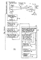
- objects such as 1a, b,1 care moved by conveyor means 2 along a feed path, as indicated by arrows 19, through a field of view 3 at which object data is required to be determined in respect of each of the objects.
- the object data may be required for the purpose of determining whether each object conforms to certain characteristics. These characteristics may be contained in object reference data, acting as a reference for comparison purposes, stored in a memory (hereinafter described). If the objects examined do not provide data conforming to the stored data they may be thereafter acted upon by action performing means, for example reject means, to displace the objects from the conveying path into a reject bin or reject path (not shown).
- a plurality of kinds of sources of illumination for example two in the present case, are utilised and a corresponding number of image forming means are provided each receptive to the wave energy of a respective source form images from which the required items of object data can be derived when these images are considered collectively.
- one such source of wave energy comprises an array of transducers 4 energised electrically and furnishing ultrasonic stress wave energy.
- This array illuminates an object 1b in the field of view 3 and the same array or part thereof is used to constitute- the receiving means for forming a first image.
- a second source of illumination comprises one providing light rays.
- this source may be constituted by natural light in the vicinity of the apparatus but preferably a specific light source 5 providing light in the visible spectrum is provided to illuminate the field of view 3 thereby substantially eliminating fluctuations in light intensity which might occur were natural light relied upon.
- a camera means 6 having an optical system for focusing an optical image of the object onto a means for converting the optical image into an electrical image in which signal generating elements are in juxtaposed or spaced relation to each other and from which a digital signal can be derived and stored by appropriate scanning means.
- the electrical image may be formed by a charge coupled device, or an array of photo diode elements and charge injection devices as in the known type of Reticon camera.
- Object data may be fed along channels 7 and 8 to a processor 9 in which means are provided for identifying data pertaining to selected object characteristics and obtained respectively from the two sources of object data, e.g. data relating to position, range, and, where appropriate, lateral dimensions of the object.
- the processor 9 may include means for comparing corresponding data items from the two sources to determine which should be passed for continued use, and which should be rejected, e.g. on grounds of quality. Further, the processor 9 may include means for forming a combined image from which object data can be extracted for various purposes. One such purpose may be to control the action performing means.
- the action performing means may include a reject means 13 controlled by a motor control circuit 14 fed with signals along conductor 15 from the processor 9 and supplying control signals along line 16 to the reject means 13.
- the action performing means may include means for controlling the direction or orientation of the transducer array 4 or the camera means 6 as hereinafter mentioned.
- the array 4 may be positionally adjusted by a means 20 coupled mechanically, as indicated at 21, to the array 4, and the camera may be positionally adjusted by a means 22 coupled, as indicated at 23, to the camera, control being effected by signals passing along lines 24, 25 respectively from the processor 9.
- each of the objects 1a, 16, 1c shaft be closely similar to each other.
- objects 1a, 1b, 1c may have differing heights h 1 , h 2 , h 3 and object 1d may have an even greater height and circumferentially extending groove formations since the ability of the apparatus embodying the different sources of illumination and plurality of image forming means to extract data from a wide variety of objects and compare the result with stored data is considerable.
- the apparatus comprises a transmitting means 4a for transmitting ultrasonic frequency swept stress wave energy to the field of view 11 which is now illustrated as concurrently containing objects a, b, c, d illuminated by the stress wave energy and from which reflections of such energy take place for reception at a receiver 4b.
- transmitting means and receiving means may be as disclosed in the specification of my granted European patent publication 0,008,455 B1.
- this transmitting and receiving means comprised a transmitting means for transmitting stress wave energy frequency swept linearly in a saw-tooth mode and radiated to a sector-shaped field of view, as now also depicted in Figure 4, in the form of a narrow beam by the strip array 4a of transducer element fed with the transmitted signal from tapping points on an analogue delay line.
- the delays imposed were varied differentially as between respective transducer elements and cyclically to produce a scanning of the beam from one boundary to the other of the field of view.
- the receiving means for receiving signals reflected from objects in the field of view included a transducer, a modulator fed with both the received incoming signals and a local signal frequency swept in correspondence with the transmitted signal, and providing an output containing difference frequency signals representing the ranges of the objects from the origin of the field of view.
- the receiver further included channels containing band pass filters for passing respective difference frequency signal bands from objects situated in respective range annuli, and the channels also contained respective time delay units to compensate for differing signal transit times pertaining to respective range annuli so that the outputs from the channels could be scanned to provide data as to the range and angular position in the field of view occupied by the object giving rise to each received signal.
- the transmitted signal may typically be swept between 150KHz-300KHz in a descending saw-tooth mode radiated in the form of a relatively angularly narrow beam typically with a focal region having a width of 6mm. and be scanned through an angle 8, for example in azimuth, over a field of view extending from an angle 0 0 to 8 max ( Figure 4) which may be approximately 60°.
- the scanning means may be duplicated to provide for scanning both in elevation and azimuth as indicated by arrows 26, 27 ( Figure 1).
- the embodiment of apparatus of the present invention now described also provides for range determination, that is whether an object is situated in any one of a number of range annuli concentric with the origin or centre 0 of the field of view.
- the apparatus thus provides for determination of the frequency difference between the transmitted signal (or a locally generated signal derived from the transmitted signal) and the received signal.
- the inner and outer radial boundaries of each range annulus correspond to a frequency pass band presented by a respective one of a series of pass band filter elements through which a difference frequency signal is passed and the output of each filter element carries signals pertaining to only one range annulus.
- T is the transit time of a wave to the object and back, is the time taken for the beam to scan angularly from its starting position to the particular sector under consideration (i.e. in which the beam is situated for irradiation of the object).
- the transit time T b wi be known from the frequency analysis of the difference frequency signal. Since both T b and to are known, therefore b can be determined at any given instant.
- t b is the instant at which the reflected signal is received from object b
- b is the instant at which the beam is positioned in the angular sector for irradiating the object b.
- box 26 represents the conversion of transit time T b to a difference frequencyf b (given by subtraction of the frequency of the transmitted or locally generated signal from the frequency of the received signal)
- box 27 represents frequency analysis (e.g. by a bank of band pass filters, one for each receiver channel) to provide determination and the value of the pass band f b and hence the range band in which the object range R b lies.
- box No.27 will, of course, inherently contain information as to the magnitude of the time T b .
- the angular position of the sector ( ⁇ b ) in which signals are transmitted to irradiate b is determined when the quantity b has been calculated.
- the range band data and the angular position data constitute the first image of the object.
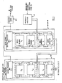
- Box No.29 represents the operation of storing this object data. This is further illustrated diagrammatically in Figures 3 and 4.
- the store B1 ( Figure 3) is loaded with signals derived from the received signals and comprises a memory system ( Figure 4) having addresses defined nationally by the intersection of N rows responding to respective range annulii and M columns corresponding to respective sectors in the field of scan.
- Stages represented by boxes 28 and 29 may be performed by a central processor unit as illustrated in Figure 3 in which the central processor unit proper (microprocessor) is designated A1, associated data and programme memories B1, C1 and input and output interfaces D1, E1. Input data is fed from the frequency analyser 28 ( Figure 3) corresponding to box No.28 of Figure 2. Operation of the central processor unit is controlled by a master clock Mc which forms a unit of the transmitter beam scanning system already mentioned.
- the central processor unit proper microprocessor
- A1 associated data and programme memories
- D1 input and output interfaces
- Input data is fed from the frequency analyser 28 ( Figure 3) corresponding to box No.28 of Figure 2.
- Operation of the central processor unit is controlled by a master clock Mc which forms a unit of the transmitter beam scanning system already mentioned.
- Box 9 indicates in more detail the operations carried out by the processor 9.
- stage 30 the object data stored in stage 29 is read, to perceive the echo signals in their relative positions and select the echo of interest, and to compare with stored reference data.
- stimuli are developed to provide for rejection (stage 14) of an object (failure to conform to stored reference data), or effect positional adjustment by camera (stage 20) and transducer array (stage 22).
- the data is processed under the control of a master clock MC, also controlling the beam scan of array 4.
- the data stored (by stage 29) is read and compared with further stored reference data for the purpose of determining whether the ascertained object data conforms or does not conform to a standard or reference represented by this further stored data.
- the action to be performed on or in relation to the object may be determined as a result of this comparison. Reading and comparison is performed in stage No.30. If the result of the comparison is sufficiently well defined for an action on the object, this may be performed by operation of a motor system (stage No.14), e.g. to reject an object.
- a further central processor unit may be provided as shown in Figure 3 comprising centrol processor unit proper A2 (a microprocessor) and further memories B2 and C2 in which the former may be used to contain the further or reference data and the latter to control the programme of reading and generating output signals to be supplied to the motor system 14.
- centrol processor unit proper A2 a microprocessor
- memories B2 and C2 in which the former may be used to contain the further or reference data and the latter to control the programme of reading and generating output signals to be supplied to the motor system 14.
- this data or parts of it such as the range of the object R b and the angle 8 b may be used to control the image processing of the camera system (commonly known in Robotic systems as the machine or artificial vision system).
- the position of the object in the image plane of the camera system is calculated in stage No.31 from the range R b and angle 8 b and the known position of the stress wave transducers.
- the camera is used to concentrate on the region containing the object image and may ignore the remainder of the field of view.
- the image forming means for producing a second image namely the camera, is able to determine those characteristics of the object which the camera system makes possible and which are absent from, or deficient in, the stress wave (first) image.
- the second image may contain more accurate data as to the position of the object in the image plane in terms of cartesian coordinates.
- the process af determining the x, y coordinates on the camera system image of an object and coordinates R b and ⁇ b in the stress wave system can follow straight forward well known methods.
- the process of comparing the object data from the first and second images with stored object data can also be carried out by known computer imaging and correlation methods.
- the process of improving the quality of the object data may be that of deleting the stored object character derived from the first image and which is of lesser quality and inserting in store the better quality data from the camera system. For example, a more accurate position of the object in the x, y coordinates of the second image may be converted to a more accurate set of values for 9 b of the first image.
- This higher quality object data is then used in effect to store a combined image and to determine the action to be performed by operation of an action performing means.
- object data collected by camera system is used, for example, either to apply data not collected, or collected imperfectly by stress wave means, to improve the overall quality of the object data produced and stored.
- the camera system may supply reliable dimensional data, e.g. between opposite boundaries of any part of the profile of the object not satisfactorily available from the stress wave (first) image whereas the latter may contain range data absent from the camera system (second) image.
- initial determination of data may be from the second image, and absences or deficiencies would then be supplemented or corrected by data derived from the first image.
- the apparatus as a whole is suitable for various purposes.
- Such dimensions may be lateral dimensions which could be initially measured angularly by scanning of the transmitter 10 to provide for signal reflection in each of two or more successively adjacent sectors of the field of view to measure an angular width.
- the camera system may be used to increase the accuracy of this measurement and also determine the position of the workpiece measured with respect to some identifiable datum point on the workpiece relatively to a datum point in the field of view.
- the stress wave system may be used to determine range of the object.
- reflections may be received of the stress wave energy from parts of the object at different ranges and a correctly dimensioned object would, therefore, produce the required range signals loaded to appropriate addresses. Failure to establish coincidence between these signals and those stored for comparison purposes at corresponding addresses would be utilised to energise a reject device either pneumatically energised, as indicated above, or a motor system of, say, a robot arm, to eject the fault workpiece mechanically.
- the combination of the stress wave system and the camera system enables recognition and position of the uppermost object to be effected.
Landscapes
- Engineering & Computer Science (AREA)
- Robotics (AREA)
- Physics & Mathematics (AREA)
- General Physics & Mathematics (AREA)
- Theoretical Computer Science (AREA)
- Investigating Or Analyzing Materials By The Use Of Ultrasonic Waves (AREA)
- Length Measuring Devices By Optical Means (AREA)
Claims (6)
Priority Applications (1)
| Application Number | Priority Date | Filing Date | Title |
|---|---|---|---|
| AT84308526T ATE41232T1 (de) | 1983-12-09 | 1984-12-07 | Verfahren und vorrichtung zur objektdatengewinnung durch maschinenvision. |
Applications Claiming Priority (4)
| Application Number | Priority Date | Filing Date | Title |
|---|---|---|---|
| NZ20654483A NZ206544A (en) | 1983-12-09 | 1983-12-09 | Machine vision enhanced by combination of data yielded by illuminating object with two energy types |
| NZ206544 | 1983-12-09 | ||
| GB8414283 | 1984-06-05 | ||
| GB08414283A GB2154822B (en) | 1983-12-09 | 1984-06-05 | Data machine vision |
Publications (3)
| Publication Number | Publication Date |
|---|---|
| EP0147962A2 EP0147962A2 (de) | 1985-07-10 |
| EP0147962A3 EP0147962A3 (en) | 1986-05-14 |
| EP0147962B1 true EP0147962B1 (de) | 1989-03-08 |
Family
ID=26287819
Family Applications (1)
| Application Number | Title | Priority Date | Filing Date |
|---|---|---|---|
| EP84308526A Expired EP0147962B1 (de) | 1983-12-09 | 1984-12-07 | Verfahren und Vorrichtung zur Objektdatengewinnung durch Maschinenvision |
Country Status (5)
| Country | Link |
|---|---|
| US (1) | US4713798A (de) |
| EP (1) | EP0147962B1 (de) |
| AU (1) | AU3637684A (de) |
| CA (1) | CA1245338A (de) |
| DE (1) | DE3477056D1 (de) |
Families Citing this family (14)
| Publication number | Priority date | Publication date | Assignee | Title |
|---|---|---|---|---|
| FR2624634B1 (fr) * | 1987-12-09 | 1994-04-29 | Schlumberger Etienne | Procede et dispositif permettant de reconstituer la forme et la position d'objets dans l'espace |
| US4964104A (en) * | 1989-01-09 | 1990-10-16 | Motorola Inc. | System for measuring position using electronic or ultrasonic devices |
| US5089972A (en) * | 1990-12-13 | 1992-02-18 | Nachman Precision Systems, Inc. | Moored ship motion determination system |
| US5161125A (en) * | 1992-05-05 | 1992-11-03 | The United States Of America As Represented By The Secretary Of The Navy | Radiation selective system for target range and imaging readout |
| DE4411448C5 (de) * | 1994-03-31 | 2009-05-14 | Sick Ag | Verfahren und Vorrichtung zur Kontrolle eines vorgegebenen Überwachungsbereichs |
| US6118302A (en) | 1996-05-28 | 2000-09-12 | Altera Corporation | Interface for low-voltage semiconductor devices |
| US6788411B1 (en) * | 1999-07-08 | 2004-09-07 | Ppt Vision, Inc. | Method and apparatus for adjusting illumination angle |
| EP1428176A4 (de) * | 2001-09-17 | 2008-03-12 | Bae Systems Information | Zusammenregistrierte akustische und optische kameras zur unterwasserabbildung |
| US7698946B2 (en) * | 2006-02-24 | 2010-04-20 | Caterpillar Inc. | System and method for ultrasonic detection and imaging |
| CN102892521A (zh) * | 2010-03-23 | 2013-01-23 | 技术资源有限公司 | 基于两个或更多材料性质分选开采的材料 |
| US11198597B2 (en) * | 2017-06-12 | 2021-12-14 | Siemens Gamesa Renewable Energy A/S | Sensing arrangement for stabilizing an offshore wind turbine installation arrangement |
| EP3783304B1 (de) * | 2017-06-22 | 2024-07-03 | Hexagon Technology Center GmbH | Kalibrierung eines triangulationssensors |
| DE102017118422B4 (de) * | 2017-08-11 | 2020-12-31 | Carl Zeiss Industrielle Messtechnik Gmbh | Vorrichtung zur vermessung und / oder bearbeitung von werkstücken und verfahren zur erfassung von werkstücken in koordinatenmessgeräten oder bearbeitungsmaschinen |
| US20230148991A1 (en) * | 2021-11-18 | 2023-05-18 | EchoNous, Inc. | Automatically detecting and quantifying anatomical structures in an ultrasound image using a customized shape prior |
Family Cites Families (13)
| Publication number | Priority date | Publication date | Assignee | Title |
|---|---|---|---|---|
| GB917197A (en) * | 1960-03-16 | 1963-01-30 | Ass Elect Ind | Improvements relating to closed loop television systems |
| FR1454451A (fr) * | 1965-08-04 | 1966-02-11 | Comp Generale Electricite | Dispositif de pointage combiné radar-laser |
| GB1211933A (en) * | 1967-02-10 | 1970-11-11 | Telefunken Patent | Improvements in or relating to radars |
| DE2132624C3 (de) * | 1971-06-30 | 1974-06-12 | Siemens Ag, 1000 Berlin Und 8000 Muenchen | Anordnung zur Ausrichtung eines schwenkbaren Gerätes auf ein sich bewegendes Objekt |
| FR2209113B1 (de) * | 1972-10-09 | 1977-04-01 | Matra Engins | |
| DE2364002C2 (de) * | 1973-12-21 | 1983-02-24 | Frey, Helmut, Dr.jur., 8000 München | Orientierungsvorrichtung für ein Gerätesystem, das sich zur Bearbeitung einer Fläche auf dieser bewegt |
| US4105990A (en) * | 1976-09-13 | 1978-08-08 | The Academy Of Applied Science Inc. | Process of and apparatus for exploring objects detected by different energy sources |
| DE2966789D1 (en) * | 1978-08-21 | 1984-04-19 | Leslie Kay | Method of and apparatus for providing information as to the existence or position of objects |
| DE2926193A1 (de) * | 1979-06-29 | 1981-01-22 | Standard Elektrik Lorenz Ag | Radargeraet, von dem polarisierte signale abgestrahlt werden |
| JPS6019438B2 (ja) * | 1980-10-16 | 1985-05-16 | 株式会社神戸製鋼所 | プレ−トフィン型熱交換器の欠陥検査方法 |
| US4447896A (en) * | 1981-06-26 | 1984-05-08 | The Academy Of Applied Science, Inc. | Method of and apparatus for combined optical and sonar detection and recording of objects |
| US4423494A (en) * | 1981-09-21 | 1983-12-27 | Sperry Corporation | Beam steerable sonar array |
| US4576286A (en) * | 1983-06-27 | 1986-03-18 | Cochlea Corporation | Parts sorting systems |
-
1984
- 1984-12-04 US US06/678,215 patent/US4713798A/en not_active Expired - Fee Related
- 1984-12-06 AU AU36376/84A patent/AU3637684A/en not_active Abandoned
- 1984-12-07 DE DE8484308526T patent/DE3477056D1/de not_active Expired
- 1984-12-07 EP EP84308526A patent/EP0147962B1/de not_active Expired
- 1984-12-07 CA CA000469603A patent/CA1245338A/en not_active Expired
Also Published As
| Publication number | Publication date |
|---|---|
| EP0147962A2 (de) | 1985-07-10 |
| AU3637684A (en) | 1985-06-13 |
| US4713798A (en) | 1987-12-15 |
| DE3477056D1 (en) | 1989-04-13 |
| CA1245338A (en) | 1988-11-22 |
| EP0147962A3 (en) | 1986-05-14 |
Similar Documents
| Publication | Publication Date | Title |
|---|---|---|
| EP0147962B1 (de) | Verfahren und Vorrichtung zur Objektdatengewinnung durch Maschinenvision | |
| US5072127A (en) | Engineered video inspecting lighting array | |
| EP1206676B1 (de) | Optisches inspektionssystem für teile im subpixel bereich | |
| EP0498811B1 (de) | Beleuchtungsarray zur videoprüfung | |
| EP0181553B1 (de) | Dreidimensionaler Bildaufnehmer | |
| EP1265065B1 (de) | Röntgenvorrichtung zum Fremdmaterialnachweis mit simultaner Detektion einer Vielzahl von Röntgenstrahlen unterschiedlicher Energien | |
| Golnabi et al. | Design and application of industrial machine vision systems | |
| JP6608292B2 (ja) | 超音波検査方法及び装置 | |
| EP0163076A1 (de) | Einrichtung zum Erzeugen einer dreidimensionalen Kopie eines Gegenstandes | |
| US4496056A (en) | Automated inspection system | |
| GB2234089A (en) | Machine vision controlled weilding system | |
| EP0523152A1 (de) | Dreidimensionales echtzeitfühlsystem. | |
| NO853377L (no) | Anordning for identifisering og registrering av flasker og/eller flaskekasser. | |
| US7406152B2 (en) | X-ray inspection apparatus, X-ray inspection method, and X-ray inspection program | |
| CN211070921U (zh) | 一种基于3d扫描法的仪表外观检测装置 | |
| US4910757A (en) | Method and apparatus for X-ray imaging | |
| CA1300368C (en) | Method and device for reconstructing the shape and position of objectsin space | |
| US5086411A (en) | Optical location systems | |
| GB2154822A (en) | Data machine vision | |
| US4165647A (en) | Scan acoustical holographic apparatus and method | |
| JPH071167B2 (ja) | 農産物等の形状識別装置 | |
| Lougheed et al. | Robot guidance using a morphological vision algorithm | |
| JPH0334801B2 (de) | ||
| CN121649831A (zh) | 工件参数检测方法、装置、设备以及存储介质 | |
| JPS6048578A (ja) | パタ−ン検出装置 |
Legal Events
| Date | Code | Title | Description |
|---|---|---|---|
| PUAI | Public reference made under article 153(3) epc to a published international application that has entered the european phase |
Free format text: ORIGINAL CODE: 0009012 |
|
| AK | Designated contracting states |
Designated state(s): AT BE CH DE FR GB IT LI LU NL SE |
|
| PUAL | Search report despatched |
Free format text: ORIGINAL CODE: 0009013 |
|
| AK | Designated contracting states |
Kind code of ref document: A3 Designated state(s): AT BE CH DE FR GB IT LI LU NL SE |
|
| 17P | Request for examination filed |
Effective date: 19861105 |
|
| 17Q | First examination report despatched |
Effective date: 19880219 |
|
| GRAA | (expected) grant |
Free format text: ORIGINAL CODE: 0009210 |
|
| AK | Designated contracting states |
Kind code of ref document: B1 Designated state(s): AT BE CH DE FR IT LI LU NL SE |
|
| PG25 | Lapsed in a contracting state [announced via postgrant information from national office to epo] |
Ref country code: SE Effective date: 19890308 Ref country code: NL Effective date: 19890308 Ref country code: LI Effective date: 19890308 Ref country code: IT Free format text: LAPSE BECAUSE OF FAILURE TO SUBMIT A TRANSLATION OF THE DESCRIPTION OR TO PAY THE FEE WITHIN THE PRESCRIBED TIME-LIMIT;WARNING: LAPSES OF ITALIAN PATENTS WITH EFFECTIVE DATE BEFORE 2007 MAY HAVE OCCURRED AT ANY TIME BEFORE 2007. THE CORRECT EFFECTIVE DATE MAY BE DIFFERENT FROM THE ONE RECORDED. Effective date: 19890308 Ref country code: CH Effective date: 19890308 Ref country code: BE Effective date: 19890308 Ref country code: AT Effective date: 19890308 |
|
| REF | Corresponds to: |
Ref document number: 41232 Country of ref document: AT Date of ref document: 19890315 Kind code of ref document: T |
|
| REF | Corresponds to: |
Ref document number: 3477056 Country of ref document: DE Date of ref document: 19890413 |
|
| REG | Reference to a national code |
Ref country code: CH Ref legal event code: PL |
|
| ET | Fr: translation filed | ||
| NLV1 | Nl: lapsed or annulled due to failure to fulfill the requirements of art. 29p and 29m of the patents act | ||
| PG25 | Lapsed in a contracting state [announced via postgrant information from national office to epo] |
Ref country code: LU Free format text: LAPSE BECAUSE OF NON-PAYMENT OF DUE FEES Effective date: 19891231 Ref country code: FR Effective date: 19891231 |
|
| PLBE | No opposition filed within time limit |
Free format text: ORIGINAL CODE: 0009261 |
|
| STAA | Information on the status of an ep patent application or granted ep patent |
Free format text: STATUS: NO OPPOSITION FILED WITHIN TIME LIMIT |
|
| 26N | No opposition filed | ||
| PG25 | Lapsed in a contracting state [announced via postgrant information from national office to epo] |
Ref country code: DE Effective date: 19900901 |
|
| REG | Reference to a national code |
Ref country code: FR Ref legal event code: ST |