EP0147978A2 - Elektrisch isolierende Artikel - Google Patents
Elektrisch isolierende Artikel Download PDFInfo
- Publication number
- EP0147978A2 EP0147978A2 EP84308642A EP84308642A EP0147978A2 EP 0147978 A2 EP0147978 A2 EP 0147978A2 EP 84308642 A EP84308642 A EP 84308642A EP 84308642 A EP84308642 A EP 84308642A EP 0147978 A2 EP0147978 A2 EP 0147978A2
- Authority
- EP
- European Patent Office
- Prior art keywords
- article
- article according
- component
- convoluted
- length
- Prior art date
- Legal status (The legal status is an assumption and is not a legal conclusion. Google has not performed a legal analysis and makes no representation as to the accuracy of the status listed.)
- Granted
Links
Images

Classifications
-
- H—ELECTRICITY
- H02—GENERATION; CONVERSION OR DISTRIBUTION OF ELECTRIC POWER
- H02G—INSTALLATION OF ELECTRIC CABLES OR LINES, OR OF COMBINED OPTICAL AND ELECTRIC CABLES OR LINES
- H02G15/00—Cable fittings
- H02G15/02—Cable terminations
- H02G15/06—Cable terminating boxes, frames or other structures
- H02G15/064—Cable terminating boxes, frames or other structures with devices for relieving electrical stress
- H02G15/068—Cable terminating boxes, frames or other structures with devices for relieving electrical stress connected to the cable shield only
-
- H—ELECTRICITY
- H01—ELECTRIC ELEMENTS
- H01B—CABLES; CONDUCTORS; INSULATORS; SELECTION OF MATERIALS FOR THEIR CONDUCTIVE, INSULATING OR DIELECTRIC PROPERTIES
- H01B17/00—Insulators or insulating bodies characterised by their form
- H01B17/32—Single insulators consisting of two or more dissimilar insulating bodies
-
- H—ELECTRICITY
- H01—ELECTRIC ELEMENTS
- H01B—CABLES; CONDUCTORS; INSULATORS; SELECTION OF MATERIALS FOR THEIR CONDUCTIVE, INSULATING OR DIELECTRIC PROPERTIES
- H01B17/00—Insulators or insulating bodies characterised by their form
- H01B17/42—Means for obtaining improved distribution of voltage; Protection against arc discharges
-
- H—ELECTRICITY
- H01—ELECTRIC ELEMENTS
- H01C—RESISTORS
- H01C7/00—Non-adjustable resistors formed as one or more layers or coatings; Non-adjustable resistors made from powdered conducting material or powdered semi-conducting material with or without insulating material
- H01C7/10—Non-adjustable resistors formed as one or more layers or coatings; Non-adjustable resistors made from powdered conducting material or powdered semi-conducting material with or without insulating material voltage responsive, i.e. varistors
- H01C7/12—Overvoltage protection resistors; Arresters
Definitions
- the present invention relates to electrically insulating articles, and to electric power cables terminated thereby and electrical insulators formed therefrom.
- the outer jacket usually of polyethylene or PVC
- the outer jacket is cut back to expose the underlying cable screen, which screen is itself cut back to expose the primary insulation.
- the primary insulation is cut back to expose the conductor of the cable, and an electrical connector is then applied to the conductor.
- the overlying components of the cable then have to be protected, and this will involve, at high voltages, providing some form of stress control. This may conveniently be achieved by the application of an heat-shrinkable polymeric tubing to the cable.
- the stress control tubing is then usually protected by a further tubing of insulating and track resistant material.
- the length of a cable termination is usually characterised by the length of exposed primary insulation, known as the "cutback length", since this is the distance along the cable from the exposed conductor, which will be at high potential, to the cable screen, which will be at earth potential.
- the cutback length is thus longer the higher the voltage rating of the cable, in order to prevent flashover and to provide the required creepage path length.
- UK Patent Specification No. 1329635 discloses an arrangement for controlling the dielectric stress at the termination of a high voltage cable, in which a stress relief tube extends over the cable insulation and is enclosed within an outer housing that is of shedded configuration and is made from porcelain.
- An insulating dielectric filler which may be a viscous fluid or a solid or elastomeric dielectric, is provided on each side of the stress relief tube to enhance support of the tube.
- a generally tubular article comprising an outer component of electrically insulating material having a convoluted outer surface extending longitudinally thereof, and an inner component of electrically stress grading material.
- the convolutions may extend along part or the whole of the outer surface of the article.
- a generally tubular article comprising an outer conponent of electrically insulating material having an outer surface that is convoluted along part of its length and that has a shedded configuration along' another part of its length.
- the article of said other aspect of the invention may have an inner component of stress grading material.
- the remaining part may be substantially cylindrical, i.e. having no substantial variation in lateral dimension, or it may be shedded, or it may have any combination of convolution/shed/ cylindrical configurations. In the latter instance, it is envisaged that the sheds may extend laterally of the article only a short distance, thus maintaining the low profile of the article.
- the convolutions may extend annularly around the article or may extend as a helix around and along the article.
- the convoluted surface may be generally sinusoidal, or otherwise have periodic protrusions, for example of rectangular, triangular or curvilinear cross-section, including castellated and saw-tooth configurations.
- the peaks and troughs of the convoluted surface may be of the same length or of different lengths longitudinally of the article, and may be regularly or irregularly spaced.
- the protrusions need not be symmetrical about the axis of the article, neither need they be continuous therearound.
- the convolutions may take the form of planes, which may be inclined to the tube axis at an angle other than 90°, and the convolutions may be offset with respect to the tubular axis.
- the protrusions may extend to one side only of the article, and may be provided by filamentary members.
- the dimensions of the convolutions, their height, separation and thickness will depend on the.size of the substrate, for example cable diameter, to which the article is to be applied, and typically, the peak-to-trough height will be larger for larger diameter substrates.
- the longitudinal peak-to-peak separation is preferably at least about 2.5mm, and preferably is not more than about 5.0mm
- the transverse peak-to-trough height is preferably at least about 1.7mm and preferably is not more than about 3.Omm.
- the longitudinal separation is about 9.0mm, and the transverse height about 7.0mm.
- the peak-to-peak separation and the peak-to-trough height would be approximately 15% and 6% respectively of the outer diameter of the article.
- the ratio of the peak-to-peak distance of convolutions of an externally-convoluted smooth-bore tube to the wall thickness is about 1:1, with a maximum of about 2:1, whereas a shed will extend laterally of its cylindrical core by an appreciably greater amount.
- a shed has a profile such that its dimension laterally of the core member is several times, at least two times, greater than its dimension longitudinally of the core member.
- shed is used herein not only to include a configuration that is inherently adapted to direct (shed) water, or other liquid pollution, away from its core member, but also to include other configurations that extend laterally of the core member by an appreciable amount even though they may not, by reason for example of their shape or orientation, be suitable for shedding water from the core member.
- an article or at least the outer insulating component thereof, in accordance with the present invention is made of a polymeric material, which may be a recoverable, for example heat-shrinkable, material.
- a polymeric material which may be a recoverable, for example heat-shrinkable, material.
- Such material will ensure a close fit of the article on to its substrate, usually dispensing with the need for any filler materials therebetween.
- the change of dimension, for example diameter, associated with recoverable articles advantageously allows a single article to be used with a range of substrates having different sizes, for example diameters, whilst obtaining a close fit thereto in each case.
- the recoverable article may have a convoluted, or convoluted and shedded configuration prior to recovery, this being essentially retained on recovery.
- the insulating component has an at least partially convoluted outer surface and a substantially smooth bore, which typically will be a cylindrical bore.
- the recoverable article may have another configuration, for example, having a smooth outer surface, prior to recovery, and be arranged to recover to the desired configuration. It will be appreciated that a polymeric article in accordance with the present invention may be manufactured conveniently in a length to suit the particular application, and that the desired outer configuration of convolutions, or convolutions and sheds, may be conveniently provided as required.
- the inner component may be a coating, or may be a tubing, of stress-grading material, and when a tubing may be of recoverable, for example heat-shrinkable, material.
- the article comprises two components, these may be co-terminous with each other.
- the two components of the article when present, may be separate, or they may be integral with one another, for example by being co-extruded, by the inner component being an internal coating on the outer component, or by the two components being bonded together by means of an intermediate bonding agent.
- the outer surface of the article may also have electrically non-tracking properties.
- any suitable insulation, and preferably non-tracking, material may be used in the articles of the invention, materials as described in British Patent Specification Nos. 1337951 and 1337952, the entire contents of which are incorporated herein by this reference, are preferred.
- the stress control material may have any suitable composition, but preferred materials include an electrically insulating polymeric material that contains carbon black; a material comprising iron oxide; a material comprising zinc oxide; a material comprising silicon carbide; and a polymeric material disclosed in UK Patent Specification Nos. 1470504 or 1470501, the entire contents of which are incorporated herein by this reference.
- the stress grading or control material used in the articles of the invention may have a linear or a non linear electrical impedance characteristic.
- the electrical impedance characteristic of a material is the relationship between the voltage applied to the material and the current consequently flowing therethrough. This can be expressed by the following equation:
- the volume resistivity of the stress grading material will be within the range of from about 10 to 10 11 ohm-cm, and will have a wall or coating thickness of between about 1 and 3.5 mm.
- a cable termination for example, having an appreciably shorter overall length, or having an enhanced specification for a given, for example conventional, length.
- Cable terminations for example, are subject to impulse and other electrical tests, and a particularly stringent test consists of the following condensation test: the terminated cable with a cutback length of 160mm is placed in an environment where its temperature is reduced to below 0°C. It is then mounted vertically in a humidity chamber that is maintained at 98% relative humidity. An a.c. voltage of 20kV is applied for 1 minute to the terminated cable conductor, whilst the cable screen is maintained at earth potential.
- terminations that satisfy this test have two sheds thereon, such that the outer diameter of the sheds is about three times that of the cable. It has been found that a cable terminated with an article in accordance with the present invention can pass this test with an outer diameter that is not appreciably larger than that of the cable itself.
- Another termination that would pass the test comprises a cylindrical tubular outer component that has no sheds thereon, but this has to be of appreciably greater length, in order to provide the necessary creepage path length, to be satisfactory.
- the excellent performance that can be obtained with a termination employing an article in accordance with the present invention is achieved within a very compact radial and longitudinal configuration. Furthermore, it has surprisingly been found that the improvement in performance of the termination is appreciably greater than would be expected simply from the increased creepage path length achieved by the convoluted outer surface. In this respect, it should also be noted that the convoluted surface does not direct water away from the surface of the article in the manner that a shed does.
- a substrate for example a porcelain or glass fibre rod, so as to form a high voltage insulator.
- the insulator may be as disclosed in European Patent Application Publication No. 125884 A, the disclosure of which is incorporated herein by this reference.
- the article consists of an outer component 2 of heat-shrinkable, non-tracking, polymeric insulating tubing, as sold by Raychem under its Trade Mark HVHC, and an inner component 4 that is a stress grading tubing as sold by Raychem under its Trade Mark SCTM.
- the SCTM tubing is of about 2 mm wall thickness, after recovery, and has a volume resistivity of about 10 8 ohm-cm.
- the outer surface of the HVHC tubing 2 is convoluted with a sinusoidal configuration, and has the following approximate measurements after recovery:
- This article has a total outer surface length along the convolutions of approximately 420mm.
- Figure 2 shows an article in which the convoluted outer surface of the outer component 6 is of square-wave castellated configuration, and has an inner stress grading component 8.
- Figure 3 shows diagrammatically an article having three sections: Section I has an outer surface that is cylindrical, Section II has an outer surface that has small sheds thereon, and Section III has an outer surface of sinusoidal convolutions. On optional inner layer 10 of stress grading material is indicated by the dotted line. It is envisaged that articles in accordance with the invention may comprise two or more of the Sections shown in Figure 3 at various locations along the length thereof.
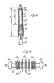
- Figure 4 shows an 11.6/20kV NAXSY 1x150mm/25 power cable that has been stripped and subsequently terminated by having heat shrunk thereon the article as configured in accordance with Figure 1.
- the cable has a polyethylene jacket 12; a screen that comprises wires 14 that provide the metal shield and that are bent back into a pigtail for convenient earthing, a conductive tape layer 16 of paper or fabric impregnated with carbon black, and conductive paint 18; primary plastic insulation 20, that is exposed for a length x of 160mm; a conductor 22, and a connecting lug 24 crimped thereonto.
- the article of Figure 1 comprising outer and inner components 2, 4 is shrunk on to the cable, so as to extend for a distance y of 270mm from the jacket 12 to the lug 24.
- the terminated cable as shown in Figure 4 was Sample No 1 to be subjected to the above-mentioned Condensation Test. Further similar samples, having insulating articles of different configuration mounted on the cable shown in Figure 4, were prepared and tested. Finally, samples with articles having an entirely cylindrical outer surface were prepared and tested for comparison. Each sample has an inner component of a linear stress grading material. The samples are described and the test results given below, in which "flashover distance”, which is the same in each sample, is the length of the insulating article, and "creepage distance", which is given only approximately, is the actual length of the outer surface of the article.
- a high voltage insulator 26 comprises a solid porcelain cylindrical core 28 having a metal end fitting 30 at each end. Further insulation between the end fittings 30 is provided by a heat-shrinkable polymeric tube 32 that has a smooth bore and an outer surface consisting of two convoluted end portions 34 and a shedded intermediate portion 36. The tube 32 is recovered over only a part of the length on to the rod 28, so as to leave exposed at each end a porclain surface. The polymeric tube 32 is thus spaced from each end fitting 30 by a refractory surface, thereby protecting the polymeric material against electrical discharges, as discussed in European Patent Application Publication No. 125884 A.
Landscapes
- Engineering & Computer Science (AREA)
- Microelectronics & Electronic Packaging (AREA)
- Power Engineering (AREA)
- Physics & Mathematics (AREA)
- Electromagnetism (AREA)
- Insulating Bodies (AREA)
- Insulated Conductors (AREA)
- Lining Or Joining Of Plastics Or The Like (AREA)
- Electrophonic Musical Instruments (AREA)
- Discharging, Photosensitive Material Shape In Electrophotography (AREA)
- Insulators (AREA)
- Cable Accessories (AREA)
Priority Applications (1)
| Application Number | Priority Date | Filing Date | Title |
|---|---|---|---|
| AT84308642T ATE63017T1 (de) | 1983-12-13 | 1984-12-12 | Elektrisch isolierende artikel. |
Applications Claiming Priority (2)
| Application Number | Priority Date | Filing Date | Title |
|---|---|---|---|
| GB838333249A GB8333249D0 (en) | 1983-12-13 | 1983-12-13 | Electrically insulating articles |
| GB8333249 | 1983-12-13 |
Publications (3)
| Publication Number | Publication Date |
|---|---|
| EP0147978A2 true EP0147978A2 (de) | 1985-07-10 |
| EP0147978A3 EP0147978A3 (en) | 1986-11-20 |
| EP0147978B1 EP0147978B1 (de) | 1991-04-24 |
Family
ID=10553237
Family Applications (1)
| Application Number | Title | Priority Date | Filing Date |
|---|---|---|---|
| EP84308642A Expired - Lifetime EP0147978B1 (de) | 1983-12-13 | 1984-12-12 | Elektrisch isolierende Artikel |
Country Status (7)
| Country | Link |
|---|---|
| US (1) | US4714800A (de) |
| EP (1) | EP0147978B1 (de) |
| JP (1) | JPS60146413A (de) |
| AT (1) | ATE63017T1 (de) |
| CA (1) | CA1250628A (de) |
| DE (1) | DE3484504D1 (de) |
| GB (1) | GB8333249D0 (de) |
Cited By (7)
| Publication number | Priority date | Publication date | Assignee | Title |
|---|---|---|---|---|
| EP0229464A1 (de) * | 1985-11-08 | 1987-07-22 | Raychem Gmbh | Brechbares Gehäuse für elektrisches Bauelement |
| EP0230103A3 (de) * | 1985-11-08 | 1987-11-04 | Raychem Gmbh | Packungsanordnung, insbesondere für Überspannungsableiter |
| EP0278606A3 (en) * | 1987-01-30 | 1989-10-25 | Dow Corning Corporation | High voltage insulators |
| WO1991006106A1 (en) * | 1989-10-17 | 1991-05-02 | Raychem Limited | Electrical insulator |
| EP0280189B1 (de) * | 1987-02-23 | 1992-12-23 | Asea Brown Boveri Ab | Überspannungsbegrenzer |
| US5637827A (en) * | 1992-06-15 | 1997-06-10 | Hubbell Incorporated | Insulator with internal passageway |
| WO1998027631A1 (en) * | 1996-12-16 | 1998-06-25 | Minnesota Mining And Manufacturing Company | Stress control for termination of a high voltage cable |
Families Citing this family (23)
| Publication number | Priority date | Publication date | Assignee | Title |
|---|---|---|---|---|
| JPH02118412U (de) * | 1989-03-08 | 1990-09-21 | ||
| JPH0541901U (ja) * | 1991-11-11 | 1993-06-08 | オージーケー技研株式会社 | 自転車用車輪 |
| US5300912A (en) * | 1992-06-09 | 1994-04-05 | Utility Solutions, Inc. | Electrical cutout for high voltage power lines |
| USD360399S (en) | 1993-09-20 | 1995-07-18 | Utility Solutions, Inc. | Insulator for an electrical cutout |
| US5945636A (en) * | 1996-04-22 | 1999-08-31 | Hubbell Incorporated | Electrical insulators with mechanical core and dielectric sheath |
| US5877453A (en) * | 1997-09-17 | 1999-03-02 | Maclean-Fogg Company | Composite insulator |
| JP3157756B2 (ja) * | 1997-10-13 | 2001-04-16 | 日本碍子株式会社 | ポリマー碍子の成形方法 |
| US5986216A (en) * | 1997-12-05 | 1999-11-16 | Hubbell Incorporated | Reinforced insulator |
| CA2349253C (en) | 2000-12-26 | 2009-11-17 | S&C Electric Company | Method and arrangement for providing a gas-tight housing joint |
| GB0103255D0 (en) * | 2001-02-09 | 2001-03-28 | Tyco Electronics Raychem Gmbh | Insulator arrangement |
| US7044458B2 (en) | 2001-04-30 | 2006-05-16 | Maclean-Fogg Company | Stabilizer bar |
| US20030080848A1 (en) * | 2001-10-29 | 2003-05-01 | Hubbell Incorporated | Unitary arrester housing and support bracket |
| JP4137480B2 (ja) * | 2002-03-27 | 2008-08-20 | 日本碍子株式会社 | ポリマー碍子 |
| US6831232B2 (en) | 2002-06-16 | 2004-12-14 | Scott Henricks | Composite insulator |
| US6952154B2 (en) | 2002-06-16 | 2005-10-04 | Maclean-Fogg Company | Composite insulator for fuse cutout |
| FR2875066B1 (fr) * | 2004-09-03 | 2006-10-27 | Nexans Sa | Agencement de liaison d'un cable d'energie a un element d'equipement |
| US7646282B2 (en) * | 2007-12-14 | 2010-01-12 | Jiri Pazdirek | Insulator for cutout switch and fuse assembly |
| US8883061B2 (en) | 2011-11-23 | 2014-11-11 | Tyco Electronics Raychem Gmbh | Cover assemblies for electrical cables and methods and kits including same |
| EP2950107A1 (de) * | 2014-05-27 | 2015-12-02 | ABB Technology AG | Spannungssensor für Hoch- und Mittelspannungsverwendung, und Verfahren zu seiner Herstellung |
| CN110462754B (zh) | 2017-02-01 | 2022-06-14 | 恩文特服务有限责任公司 | 低烟无卤自动调节发热电缆 |
| US10530143B2 (en) * | 2017-09-21 | 2020-01-07 | Accessesp Uk Limited | Stress control cones for downhole electrical power system tubing encapsulated power cables |
| EP4007658A1 (de) | 2019-08-01 | 2022-06-08 | Infinite Cooling Inc. | Systeme und verfahren zur flüssigkeitsentnahme aus einem gasstrom |
| WO2021021370A1 (en) * | 2019-08-01 | 2021-02-04 | Infinite Cooling Inc. | Panels for use in collecting fluid from a gas stream |
Family Cites Families (21)
| Publication number | Priority date | Publication date | Assignee | Title |
|---|---|---|---|---|
| US1168019A (en) * | 1915-03-05 | 1916-01-11 | Horace P Liversidge | Pothead or connector for electrical conductors. |
| US2945913A (en) * | 1956-04-27 | 1960-07-19 | Ite Circuit Breaker Ltd | Prefabricated stress relief cone |
| GB881266A (en) * | 1957-07-19 | 1961-11-01 | Siemens Ag | Improvements in or relating to pin-type electric insulators |
| DE1119938B (de) * | 1957-07-19 | 1961-12-21 | Siemens Ag | Innenraumstuetzisolator |
| NL6506728A (de) * | 1964-05-29 | 1965-07-26 | ||
| US3377420A (en) * | 1965-04-16 | 1968-04-09 | Elastic Stop Nut Corp | Device for terminating outdoor electric cables |
| US3585274A (en) * | 1969-09-15 | 1971-06-15 | Minnesota Mining & Mfg | Relief of dielectric stress in high voltage cable connections |
| US3673305A (en) * | 1970-11-04 | 1972-06-27 | Detroit Edison Co | Capacitively graded modular pothead for h-v cable |
| US3730970A (en) * | 1971-10-04 | 1973-05-01 | Minnesota Mining & Mfg | Terminal with grease retaining members |
| BE794352A (fr) * | 1972-01-21 | 1973-05-16 | Joslyn Mfg & Supply Co | Dispositif d'extremite dit de terminaison pour cables a haute tension pour leur fermeture ou leur jonction a un autre cable |
| GB1433129A (en) * | 1972-09-01 | 1976-04-22 | Raychem Ltd | Materials having non-linear resistance characteristics |
| US3796821A (en) * | 1972-10-06 | 1974-03-12 | G & W Electric Speciality Co | High voltage cable termination |
| US4045604A (en) * | 1974-10-08 | 1977-08-30 | Raychem Limited | Recoverable article with outwardly extending hollow heat flanges; kit including such article and a cylindrical substrate; and method of making such article |
| GB1530995A (en) * | 1974-10-08 | 1978-11-01 | Raychem Ltd | Article and method for covering substrates and composite structures so made |
| JPS5815298B2 (ja) * | 1977-06-07 | 1983-03-24 | 日東電工株式会社 | ベロ−ズ構造を有する熱収縮性チュ−ブの製造法 |
| FR2412150A1 (fr) * | 1977-12-14 | 1979-07-13 | Ceraver | Isolateur electrique de ligne en matiere organique |
| AU531523B2 (en) * | 1978-12-01 | 1983-08-25 | Raychem Gmbh | Electrical apparatus |
| DE2904955B2 (de) * | 1979-02-02 | 1980-11-20 | Siemens Ag, 1000 Berlin Und 8000 Muenchen | Aufschiebbarer Endenabschluß für geschirmte Starkstromkabeladern mit sektorförmigem Aderquerschnitt |
| FR2456410A1 (fr) * | 1979-05-11 | 1980-12-05 | Electricite Radio Aviat Meca | Perfectionnements aux dispositifs de protection pour extremites de cables electriques a moyenne tension |
| FR2523361A1 (fr) * | 1982-03-15 | 1983-09-16 | Ceraver | Procede de fabrication d'un revetement isolant a profil cannele sur un support cylindrique, et dispositif de mise en oeuvre du procede |
| GB8312892D0 (en) * | 1983-05-11 | 1983-06-15 | Raychem Ltd | Electrical insulator |
-
1983
- 1983-12-13 GB GB838333249A patent/GB8333249D0/en active Pending
-
1984
- 1984-12-12 DE DE8484308642T patent/DE3484504D1/de not_active Expired - Lifetime
- 1984-12-12 AT AT84308642T patent/ATE63017T1/de not_active IP Right Cessation
- 1984-12-12 EP EP84308642A patent/EP0147978B1/de not_active Expired - Lifetime
- 1984-12-12 CA CA000469920A patent/CA1250628A/en not_active Expired
- 1984-12-13 JP JP59264338A patent/JPS60146413A/ja active Pending
-
1986
- 1986-06-24 US US06/881,504 patent/US4714800A/en not_active Expired - Fee Related
Cited By (11)
| Publication number | Priority date | Publication date | Assignee | Title |
|---|---|---|---|---|
| EP0229464A1 (de) * | 1985-11-08 | 1987-07-22 | Raychem Gmbh | Brechbares Gehäuse für elektrisches Bauelement |
| EP0230103A3 (de) * | 1985-11-08 | 1987-11-04 | Raychem Gmbh | Packungsanordnung, insbesondere für Überspannungsableiter |
| US4812944A (en) * | 1985-11-08 | 1989-03-14 | Raychem Gmbh | Electrical equipment |
| EP0278606A3 (en) * | 1987-01-30 | 1989-10-25 | Dow Corning Corporation | High voltage insulators |
| EP0280189B1 (de) * | 1987-02-23 | 1992-12-23 | Asea Brown Boveri Ab | Überspannungsbegrenzer |
| WO1991006106A1 (en) * | 1989-10-17 | 1991-05-02 | Raychem Limited | Electrical insulator |
| US5298301A (en) * | 1989-10-17 | 1994-03-29 | Raychem Limited | Electrical insulator |
| AU653501B2 (en) * | 1989-10-17 | 1994-10-06 | Raychem Limited | Electrical insulator |
| US5637827A (en) * | 1992-06-15 | 1997-06-10 | Hubbell Incorporated | Insulator with internal passageway |
| US6340794B1 (en) | 1995-09-06 | 2002-01-22 | Minnesota Mining And Manufacturing Company | Stress control for termination of a high voltage cable |
| WO1998027631A1 (en) * | 1996-12-16 | 1998-06-25 | Minnesota Mining And Manufacturing Company | Stress control for termination of a high voltage cable |
Also Published As
| Publication number | Publication date |
|---|---|
| GB8333249D0 (en) | 1984-01-18 |
| EP0147978A3 (en) | 1986-11-20 |
| US4714800A (en) | 1987-12-22 |
| DE3484504D1 (de) | 1991-05-29 |
| JPS60146413A (ja) | 1985-08-02 |
| EP0147978B1 (de) | 1991-04-24 |
| ATE63017T1 (de) | 1991-05-15 |
| CA1250628A (en) | 1989-02-28 |
Similar Documents
| Publication | Publication Date | Title |
|---|---|---|
| EP0147978B1 (de) | Elektrisch isolierende Artikel | |
| EP0121986B1 (de) | Vorrichtung und Verfahren zur Verminderung elektrischer Beanspruchung | |
| US5936825A (en) | Rise pole termination/arrestor combination | |
| US4551915A (en) | Method for terminating a high voltage cable | |
| US4963819A (en) | High voltage apparatus | |
| EP0125884B1 (de) | Elektrischer Isolator | |
| EP1008218B1 (de) | Trockener elektrischer kabelendverschluss | |
| EP0780949B1 (de) | Universeller Kabeladapter, mit Hilfe des Adapters hergestellte Kabelverbindung sowie Verfahren zur Herstellung derselben | |
| US4485269A (en) | Cable sealing | |
| EP0272131B1 (de) | Hochspannungskabel | |
| US4847450A (en) | Stress graded electrical bushing and method of making same | |
| JPH0515042A (ja) | 保護スリーブならびにケーブル成端部又は接続部の保護方法 | |
| US3585274A (en) | Relief of dielectric stress in high voltage cable connections | |
| JPS62133685A (ja) | ケ−ブル接続装置 | |
| US3796821A (en) | High voltage cable termination | |
| JPH07272566A (ja) | 電気ケーブル端子 | |
| CN110235208B (zh) | 中压和高压线缆应用的多层应力控制制品及干式接线端 | |
| US4524404A (en) | High voltage insulator assemblage having specially-chosen series resistance | |
| GB2125637A (en) | Providing insulation and shielding to an electrical component/terminal combination | |
| GB2097203A (en) | Cable sealing | |
| GB2248845A (en) | Sealing composition for electric cable terminations | |
| Wandmacher et al. | New silicone cold shrink termination | |
| AU598760B2 (en) | Capacitor tubes for high voltage power cables terminations | |
| HU206169B (en) | Cable terminal |
Legal Events
| Date | Code | Title | Description |
|---|---|---|---|
| PUAI | Public reference made under article 153(3) epc to a published international application that has entered the european phase |
Free format text: ORIGINAL CODE: 0009012 |
|
| 17P | Request for examination filed |
Effective date: 19841227 |
|
| AK | Designated contracting states |
Designated state(s): AT BE CH DE FR GB IT LI NL SE |
|
| PUAL | Search report despatched |
Free format text: ORIGINAL CODE: 0009013 |
|
| AK | Designated contracting states |
Kind code of ref document: A3 Designated state(s): AT BE CH DE FR GB IT LI NL SE |
|
| 17Q | First examination report despatched |
Effective date: 19880607 |
|
| GRAA | (expected) grant |
Free format text: ORIGINAL CODE: 0009210 |
|
| AK | Designated contracting states |
Kind code of ref document: B1 Designated state(s): AT BE CH DE FR GB IT LI NL SE |
|
| PG25 | Lapsed in a contracting state [announced via postgrant information from national office to epo] |
Ref country code: SE Effective date: 19910424 Ref country code: NL Effective date: 19910424 Ref country code: LI Effective date: 19910424 Ref country code: IT Free format text: LAPSE BECAUSE OF FAILURE TO SUBMIT A TRANSLATION OF THE DESCRIPTION OR TO PAY THE FEE WITHIN THE PRESCRIBED TIME-LIMIT;WARNING: LAPSES OF ITALIAN PATENTS WITH EFFECTIVE DATE BEFORE 2007 MAY HAVE OCCURRED AT ANY TIME BEFORE 2007. THE CORRECT EFFECTIVE DATE MAY BE DIFFERENT FROM THE ONE RECORDED. Effective date: 19910424 Ref country code: CH Effective date: 19910424 Ref country code: BE Effective date: 19910424 Ref country code: AT Effective date: 19910424 |
|
| REF | Corresponds to: |
Ref document number: 63017 Country of ref document: AT Date of ref document: 19910515 Kind code of ref document: T |
|
| REF | Corresponds to: |
Ref document number: 3484504 Country of ref document: DE Date of ref document: 19910529 |
|
| ET | Fr: translation filed | ||
| REG | Reference to a national code |
Ref country code: CH Ref legal event code: PL |
|
| NLV1 | Nl: lapsed or annulled due to failure to fulfill the requirements of art. 29p and 29m of the patents act | ||
| PGFP | Annual fee paid to national office [announced via postgrant information from national office to epo] |
Ref country code: GB Payment date: 19911129 Year of fee payment: 8 |
|
| PGFP | Annual fee paid to national office [announced via postgrant information from national office to epo] |
Ref country code: FR Payment date: 19911209 Year of fee payment: 8 |
|
| PGFP | Annual fee paid to national office [announced via postgrant information from national office to epo] |
Ref country code: DE Payment date: 19920131 Year of fee payment: 8 |
|
| PLBE | No opposition filed within time limit |
Free format text: ORIGINAL CODE: 0009261 |
|
| STAA | Information on the status of an ep patent application or granted ep patent |
Free format text: STATUS: NO OPPOSITION FILED WITHIN TIME LIMIT |
|
| 26N | No opposition filed | ||
| PG25 | Lapsed in a contracting state [announced via postgrant information from national office to epo] |
Ref country code: GB Effective date: 19921212 |
|
| GBPC | Gb: european patent ceased through non-payment of renewal fee |
Effective date: 19921212 |
|
| PG25 | Lapsed in a contracting state [announced via postgrant information from national office to epo] |
Ref country code: FR Effective date: 19930831 |
|
| PG25 | Lapsed in a contracting state [announced via postgrant information from national office to epo] |
Ref country code: DE Effective date: 19930901 |
|
| REG | Reference to a national code |
Ref country code: FR Ref legal event code: ST |