EP0148034B1 - Laser-Endoskop - Google Patents
Laser-Endoskop Download PDFInfo
- Publication number
- EP0148034B1 EP0148034B1 EP84309148A EP84309148A EP0148034B1 EP 0148034 B1 EP0148034 B1 EP 0148034B1 EP 84309148 A EP84309148 A EP 84309148A EP 84309148 A EP84309148 A EP 84309148A EP 0148034 B1 EP0148034 B1 EP 0148034B1
- Authority
- EP
- European Patent Office
- Prior art keywords
- optical fibre
- optical
- cable
- fibre bundle
- laser
- Prior art date
- Legal status (The legal status is an assumption and is not a legal conclusion. Google has not performed a legal analysis and makes no representation as to the accuracy of the status listed.)
- Expired - Lifetime
Links
- 239000000835 fiber Substances 0.000 claims description 54
- 239000013307 optical fiber Substances 0.000 claims description 54
- 230000003287 optical effect Effects 0.000 claims description 19
- 230000001427 coherent effect Effects 0.000 claims description 13
- 238000012634 optical imaging Methods 0.000 claims description 7
- 238000001356 surgical procedure Methods 0.000 claims description 6
- 238000003384 imaging method Methods 0.000 claims description 5
- 238000003780 insertion Methods 0.000 claims description 5
- 230000037431 insertion Effects 0.000 claims description 5
- 238000011282 treatment Methods 0.000 claims description 5
- 239000008280 blood Substances 0.000 claims description 4
- 210000004369 blood Anatomy 0.000 claims description 4
- 239000012530 fluid Substances 0.000 claims description 4
- 230000005540 biological transmission Effects 0.000 claims description 3
- CURLTUGMZLYLDI-UHFFFAOYSA-N Carbon dioxide Chemical compound O=C=O CURLTUGMZLYLDI-UHFFFAOYSA-N 0.000 description 6
- XKRFYHLGVUSROY-UHFFFAOYSA-N Argon Chemical compound [Ar] XKRFYHLGVUSROY-UHFFFAOYSA-N 0.000 description 4
- 210000001367 artery Anatomy 0.000 description 3
- 210000001124 body fluid Anatomy 0.000 description 3
- 239000010839 body fluid Substances 0.000 description 3
- 229910002092 carbon dioxide Inorganic materials 0.000 description 3
- 239000007789 gas Substances 0.000 description 3
- 238000005286 illumination Methods 0.000 description 3
- 238000002430 laser surgery Methods 0.000 description 3
- 208000000913 Kidney Calculi Diseases 0.000 description 2
- 206010029148 Nephrolithiasis Diseases 0.000 description 2
- VYPSYNLAJGMNEJ-UHFFFAOYSA-N Silicium dioxide Chemical compound O=[Si]=O VYPSYNLAJGMNEJ-UHFFFAOYSA-N 0.000 description 2
- 239000004809 Teflon Substances 0.000 description 2
- 229920006362 Teflon® Polymers 0.000 description 2
- 229910052786 argon Inorganic materials 0.000 description 2
- 230000008878 coupling Effects 0.000 description 2
- 238000010168 coupling process Methods 0.000 description 2
- 238000005859 coupling reaction Methods 0.000 description 2
- 238000010586 diagram Methods 0.000 description 2
- 239000003589 local anesthetic agent Substances 0.000 description 2
- 239000000463 material Substances 0.000 description 2
- 238000000034 method Methods 0.000 description 2
- 230000037361 pathway Effects 0.000 description 2
- 239000000523 sample Substances 0.000 description 2
- 230000000007 visual effect Effects 0.000 description 2
- 206010028980 Neoplasm Diseases 0.000 description 1
- 229910000831 Steel Inorganic materials 0.000 description 1
- 208000007097 Urinary Bladder Neoplasms Diseases 0.000 description 1
- 208000027418 Wounds and injury Diseases 0.000 description 1
- 210000003815 abdominal wall Anatomy 0.000 description 1
- 230000004913 activation Effects 0.000 description 1
- 239000000853 adhesive Substances 0.000 description 1
- 230000001070 adhesive effect Effects 0.000 description 1
- 210000004556 brain Anatomy 0.000 description 1
- 229910052799 carbon Inorganic materials 0.000 description 1
- 239000001569 carbon dioxide Substances 0.000 description 1
- 201000001883 cholelithiasis Diseases 0.000 description 1
- 239000011248 coating agent Substances 0.000 description 1
- 238000000576 coating method Methods 0.000 description 1
- 201000010099 disease Diseases 0.000 description 1
- 208000037265 diseases, disorders, signs and symptoms Diseases 0.000 description 1
- 239000000428 dust Substances 0.000 description 1
- 239000004744 fabric Substances 0.000 description 1
- NBVXSUQYWXRMNV-UHFFFAOYSA-N fluoromethane Chemical compound FC NBVXSUQYWXRMNV-UHFFFAOYSA-N 0.000 description 1
- 208000001130 gallstones Diseases 0.000 description 1
- 238000002329 infrared spectrum Methods 0.000 description 1
- 208000014674 injury Diseases 0.000 description 1
- 230000001678 irradiating effect Effects 0.000 description 1
- 238000005304 joining Methods 0.000 description 1
- 210000003734 kidney Anatomy 0.000 description 1
- 238000013532 laser treatment Methods 0.000 description 1
- 238000004519 manufacturing process Methods 0.000 description 1
- 230000021332 multicellular organism growth Effects 0.000 description 1
- 230000002093 peripheral effect Effects 0.000 description 1
- 238000003825 pressing Methods 0.000 description 1
- 230000001681 protective effect Effects 0.000 description 1
- 239000000377 silicon dioxide Substances 0.000 description 1
- 229910001220 stainless steel Inorganic materials 0.000 description 1
- 239000010935 stainless steel Substances 0.000 description 1
- 239000010959 steel Substances 0.000 description 1
- 230000008733 trauma Effects 0.000 description 1
- 230000002485 urinary effect Effects 0.000 description 1
- 210000003462 vein Anatomy 0.000 description 1
Images



Classifications
-
- A—HUMAN NECESSITIES
- A61—MEDICAL OR VETERINARY SCIENCE; HYGIENE
- A61B—DIAGNOSIS; SURGERY; IDENTIFICATION
- A61B18/00—Surgical instruments, devices or methods for transferring non-mechanical forms of energy to or from the body
- A61B18/18—Surgical instruments, devices or methods for transferring non-mechanical forms of energy to or from the body by applying electromagnetic radiation, e.g. microwaves
- A61B18/20—Surgical instruments, devices or methods for transferring non-mechanical forms of energy to or from the body by applying electromagnetic radiation, e.g. microwaves using laser
-
- A—HUMAN NECESSITIES
- A61—MEDICAL OR VETERINARY SCIENCE; HYGIENE
- A61B—DIAGNOSIS; SURGERY; IDENTIFICATION
- A61B1/00—Instruments for performing medical examinations of the interior of cavities or tubes of the body by visual or photographical inspection, e.g. endoscopes; Illuminating arrangements therefor
- A61B1/00112—Connection or coupling means
- A61B1/00117—Optical cables in or with an endoscope
-
- A—HUMAN NECESSITIES
- A61—MEDICAL OR VETERINARY SCIENCE; HYGIENE
- A61B—DIAGNOSIS; SURGERY; IDENTIFICATION
- A61B1/00—Instruments for performing medical examinations of the interior of cavities or tubes of the body by visual or photographical inspection, e.g. endoscopes; Illuminating arrangements therefor
- A61B1/00112—Connection or coupling means
- A61B1/00121—Connectors, fasteners and adapters, e.g. on the endoscope handle
- A61B1/00126—Connectors, fasteners and adapters, e.g. on the endoscope handle optical, e.g. for light supply cables
-
- A—HUMAN NECESSITIES
- A61—MEDICAL OR VETERINARY SCIENCE; HYGIENE
- A61B—DIAGNOSIS; SURGERY; IDENTIFICATION
- A61B1/00—Instruments for performing medical examinations of the interior of cavities or tubes of the body by visual or photographical inspection, e.g. endoscopes; Illuminating arrangements therefor
- A61B1/00112—Connection or coupling means
- A61B1/00121—Connectors, fasteners and adapters, e.g. on the endoscope handle
- A61B1/00128—Connectors, fasteners and adapters, e.g. on the endoscope handle mechanical, e.g. for tubes or pipes
-
- A—HUMAN NECESSITIES
- A61—MEDICAL OR VETERINARY SCIENCE; HYGIENE
- A61B—DIAGNOSIS; SURGERY; IDENTIFICATION
- A61B1/00—Instruments for performing medical examinations of the interior of cavities or tubes of the body by visual or photographical inspection, e.g. endoscopes; Illuminating arrangements therefor
- A61B1/04—Instruments for performing medical examinations of the interior of cavities or tubes of the body by visual or photographical inspection, e.g. endoscopes; Illuminating arrangements therefor combined with photographic or television appliances
- A61B1/042—Instruments for performing medical examinations of the interior of cavities or tubes of the body by visual or photographical inspection, e.g. endoscopes; Illuminating arrangements therefor combined with photographic or television appliances characterised by a proximal camera, e.g. a CCD camera
-
- A—HUMAN NECESSITIES
- A61—MEDICAL OR VETERINARY SCIENCE; HYGIENE
- A61B—DIAGNOSIS; SURGERY; IDENTIFICATION
- A61B1/00—Instruments for performing medical examinations of the interior of cavities or tubes of the body by visual or photographical inspection, e.g. endoscopes; Illuminating arrangements therefor
- A61B1/313—Instruments for performing medical examinations of the interior of cavities or tubes of the body by visual or photographical inspection, e.g. endoscopes; Illuminating arrangements therefor for introducing through surgical openings, e.g. laparoscopes
- A61B1/317—Instruments for performing medical examinations of the interior of cavities or tubes of the body by visual or photographical inspection, e.g. endoscopes; Illuminating arrangements therefor for introducing through surgical openings, e.g. laparoscopes for bones or joints, e.g. osteoscopes, arthroscopes
-
- A—HUMAN NECESSITIES
- A61—MEDICAL OR VETERINARY SCIENCE; HYGIENE
- A61B—DIAGNOSIS; SURGERY; IDENTIFICATION
- A61B18/00—Surgical instruments, devices or methods for transferring non-mechanical forms of energy to or from the body
- A61B18/18—Surgical instruments, devices or methods for transferring non-mechanical forms of energy to or from the body by applying electromagnetic radiation, e.g. microwaves
- A61B18/20—Surgical instruments, devices or methods for transferring non-mechanical forms of energy to or from the body by applying electromagnetic radiation, e.g. microwaves using laser
- A61B18/22—Surgical instruments, devices or methods for transferring non-mechanical forms of energy to or from the body by applying electromagnetic radiation, e.g. microwaves using laser the beam being directed along or through a flexible conduit, e.g. an optical fibre; Couplings or hand-pieces therefor
- A61B18/24—Surgical instruments, devices or methods for transferring non-mechanical forms of energy to or from the body by applying electromagnetic radiation, e.g. microwaves using laser the beam being directed along or through a flexible conduit, e.g. an optical fibre; Couplings or hand-pieces therefor with a catheter
-
- G—PHYSICS
- G02—OPTICS
- G02B—OPTICAL ELEMENTS, SYSTEMS OR APPARATUS
- G02B23/00—Telescopes, e.g. binoculars; Periscopes; Instruments for viewing the inside of hollow bodies; Viewfinders; Optical aiming or sighting devices
- G02B23/24—Instruments or systems for viewing the inside of hollow bodies, e.g. fibrescopes
- G02B23/2407—Optical details
- G02B23/2461—Illumination
- G02B23/2469—Illumination using optical fibres
-
- A—HUMAN NECESSITIES
- A61—MEDICAL OR VETERINARY SCIENCE; HYGIENE
- A61B—DIAGNOSIS; SURGERY; IDENTIFICATION
- A61B18/00—Surgical instruments, devices or methods for transferring non-mechanical forms of energy to or from the body
- A61B2018/00636—Sensing and controlling the application of energy
-
- A—HUMAN NECESSITIES
- A61—MEDICAL OR VETERINARY SCIENCE; HYGIENE
- A61B—DIAGNOSIS; SURGERY; IDENTIFICATION
- A61B18/00—Surgical instruments, devices or methods for transferring non-mechanical forms of energy to or from the body
- A61B18/18—Surgical instruments, devices or methods for transferring non-mechanical forms of energy to or from the body by applying electromagnetic radiation, e.g. microwaves
- A61B18/20—Surgical instruments, devices or methods for transferring non-mechanical forms of energy to or from the body by applying electromagnetic radiation, e.g. microwaves using laser
- A61B18/22—Surgical instruments, devices or methods for transferring non-mechanical forms of energy to or from the body by applying electromagnetic radiation, e.g. microwaves using laser the beam being directed along or through a flexible conduit, e.g. an optical fibre; Couplings or hand-pieces therefor
- A61B2018/2205—Characteristics of fibres
- A61B2018/2211—Plurality of fibres
- A61B2018/2216—Braided or helically wound
-
- A—HUMAN NECESSITIES
- A61—MEDICAL OR VETERINARY SCIENCE; HYGIENE
- A61B—DIAGNOSIS; SURGERY; IDENTIFICATION
- A61B18/00—Surgical instruments, devices or methods for transferring non-mechanical forms of energy to or from the body
- A61B18/18—Surgical instruments, devices or methods for transferring non-mechanical forms of energy to or from the body by applying electromagnetic radiation, e.g. microwaves
- A61B18/20—Surgical instruments, devices or methods for transferring non-mechanical forms of energy to or from the body by applying electromagnetic radiation, e.g. microwaves using laser
- A61B18/22—Surgical instruments, devices or methods for transferring non-mechanical forms of energy to or from the body by applying electromagnetic radiation, e.g. microwaves using laser the beam being directed along or through a flexible conduit, e.g. an optical fibre; Couplings or hand-pieces therefor
- A61B2018/2244—Features of optical fibre cables, e.g. claddings
Definitions
- This invention relates to endoscope apparatus for viewing and/or treatment within body cavities by non-surgical or micro-surgical procedures.
- US-A-3,858,577 discloses an endoscope of substantial size for performing laser surgery.
- light is used through fibre optics to illuminate the operating site and laser light is used to perform a surgical procedure.
- US-A-4,011,403 discloses a fibre optic laser endoscope.
- the device utilizes a laser beam as a light source and an optical fibre as a light transmitter.
- the sensing means includes a TV camera located at the investigated site.
- the laser beam produces three different wavelengths which produce white light. Also ultraviolet or infrared light can be used.
- the camera is separate from the fibre optics and the laser.
- US-A-4,327,738, on which the preamble of claim 1 is based discloses a relatively bulky endoscopic cable assembly for simultaneous visual and ultrasonic imaging of body cavities.
- the cable assembly includes an optical fibre bundle for transmitting light to the distal end for illuminating the cavity, and a further optical fibre bundle for transmitting an image of the cavity focussed on the distal end by an objective lens system adjacent the distal end.
- These optical fibre bundles are connected to separate optical cables for connection to a remote unit including a light source and a video camera and viewing screen.
- US-A-3,089,484 discloses a thin flexible endoscope cable for insertion through narrow passages and ducts of the body, the cable having an outer diameter between 2.25 mm and 3.25 mm and comprising an annular bundle of optical fibres for conducting illuminating light surrounding a central, image transmitting bundle of optical fibres.
- the invention provides apparatus for viewing and/or treatment within body cavities by non-surgical or micro-surgical procedures, the apparatus comprising a cable for insertion into a body cavity, said cable including optical fibre means for transmitting light therethrough from a proximate end to a distal end of said cable to illuminate the body cavity, a coherent optical fibre bundle having planar proximate and distal ends adjacent the proximate and distal ends respectively of the optical fibre means, and optical lens means at the distal end of the optical fibre bundle to form an image of a portion of the cavity on the distal end of said optical fibre bundle for transmission through the cable; and a remote viewing unit including a light source connectable to the proximate end of said optical fibre means, optical imaging means connectable to the proximate end of said optical fibre bundle for projecting an image of the portion of the body cavity transmitted through said fibre bundle to its proximate end, viewing means connected to the imaging means for displaying the image projected thereby, and focusing means for focusing the image displayed by said viewing means, characterised in that the light
- the single optical fibre may be spirally wound around the outside of the cable.
- additional fibres could be used for transmitting light from a different laser light source, such as an argon laser or YAG laser for laser surgery such as cauterizing tissue or for destorying tumors and other undesirable body growths such as kidney stones and gall stones. It could also be used for destroying placque within an artery, and particularly arteries near the heart.
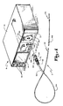
- a face plate 26 At the right end of front panel 12 is a face plate 26 in which a receptacle 28 is provided for establishing an interface between remote unit R and the cable assembly C, as will be discussed in more detail.
- a receptacle 28 Above receptacle 28 is an arcuate slot 30 in which a knob 32 can be moved from one end to the other to select a laser fiber of the cable assembly C through which a beam of laser light is to be directed. This feature will also be discussed in more detail below.
- the interface connector 38 can be inserted in receptacle 28 and tip 36, as well as a portion of cable assembly 34, can be inserted into the body of the patient either through a natural body canal leading to the area to be investigated or through a needle that has been inserted into the body at an appropriate location.
- tip 36 and cable assembly 32 can, be inserted in the urinary canal to investigate the bladder or kidneys. Because of the micro-thin diameter of the cable assembly, this can be accomplished with little or no discomfort to the patient. Alternatively, it can be inserted through a needle through the abdominal wall, and this may be done with the use of local anesthetic.
- the physician can investigate portions of the body which either were not previously accessible or which were accessible only through the use of invasive operative techniques causing much trauma and discomfort to the patient.
- the device can be inserted into the arteries and veins; in the brain; in the spine; and the joints. Most procedures-for which this invention is intended can be performed on an outpatient basis or with a very minimal hospital stay.
- the laser button 20 can be activated to energize the laser diode so that the laser light is projected through the single fiber to the site to illuminate it.
- the reflected light and image from the site is reflected back through the cable assembly for viewing on screen 14.
- the knobs 16 can be appropriately adjusted to provide the desired brightness, contrast and vertical hold.
- knob 24 can be adjusted to bring the image into proper focus.
- other physicians can view the screen along with the doctor whereby the device can serve to provide a means whereby more than one physician can be consulted concerning the condition existing within the body and additionally the device can be used as a training tool for students or other doctors.
- An output port (not shown), which is TV compatible, is provided for video recording.
- Cable 34 can be of any desired length but typically might be on the order of 1.0 to 1.5 meters in length.
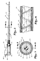
- a coherent fiber bundle 40 for transmitting an image from the site in the body cavity back to the viewing screen 14.
- This coherent fiber bundle can be extruded together during manufacture wherein the individual fibers adhere to each other along their peripheral edges and are coated with a silica coating and a jacket 42 which may be made of Teflon or PVC or some other similar material.
- coherent fiber bundle 40 can comprise anywhere from 10,000 to 50,000 individual fibers having a numerical aperture of 0.28 and having a core diameter of approximately 4 micrometers, the overall diameter with jacket 42 being approximately 0.5 to 2.5 millimeters.
- a space is provided between inner jacket 42 and an-outer jacket 44 wherein a single laser fiber 46 and a redundant laser fiber 48 run spirally from interface connector 38 at the proximate end of cable assembly C to tip 36 on the distal end of cable assembly C.
- This outer jacket 44 can also be made of a fluorocarbon material such as Teflon, or PVC.
- an outer protective sheathing 50 is provided along a portion of the length of outer jacket 44 and may be made of a fabric braid PVC covering or may be a flexible steel covering.
- the length of the cable extending beyond sheathing 50 can be on the order of 15 to 20 cm.
- a strain relief coil spring 52 is provided at the end of the cable, adjacent interface connector 38 having a length on the order of 7 to 9 mm.
- additional tubular passageways 54 can be provided in outer jacket 44 for directing CO2 gas or other fluid from a suitable source located in or adjacent to remote unit R through tip 36 to the desired site in the body cavity to blow away or wash away body fluids such as blood so that the particular area of the site to be viewed can be seen.
- the total diameter of outer jacket 44 will be on the order of 1.5 to 3.5 mm, whereas the outer diameter of sheathing 50 will be on the order on 5 to 6 mm. However, the sheathing portion 50 will never be inserted into the body cavity and therefore this larger size is not objectionable.
- a third, single laser fiber such as fiber 53 shown in phantom in Figures 3 and 4, can be provided for use in laser treatment.
- a second laser such as an argon laser could be provided in remote unit R and optically coupled with fiber 53 for performing laser surgery at the investigative site. laser light for this purpose in the 500 nm. range has been found to be satisfactory.
- lenses are for the purpose of focusing an image reflected from the body cavity so that this image can be transmitted by coherent fiber bundle 40 back to remote unit R. It may be that a lens will be positioned in the place of planar window 64, which can then be omitted.
- a suitable adhesive can be provided in recess 60 for joining the jackets 42 and 44 thereto and to prevent moisture from entering tip 36.
- jet openings 66 are positioned around the end of tip 36 and communicate with passageways 54 in outer jacket 44 so that CO2 gas or other fluid can be expelled through the jet openings to clear away any blood or other body fluids that might interfere with the illumination and reflection of the image of the area of the body cavity being viewed.
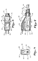
- the proximate end of cable 34 extends through interface connector 38.
- the coherent fiber bundle 40 extends completely through connector 38 and has a polished end surface 67 which is coterminous with end face 68 of interface connector 38, as shown.
- Jackets 42 and 44 extend a short distance into a recess 69 in connector 38, as shown.
- strain relief spring 52 includes a flange 70 by which it is held in place by a lock nut 72 received over threaded neck 74 on interface connector 38.
- a passageway 76 extends along the upper edge of the neck and communicates with upwardly extending passageway 78 which in turn connects divergent passageways 80 and 82 which in turn interconnect with longitudinal passageways 84 and 86, respectively.
- spaced above polished end 67 of coherent fiber bundle 40 are a pair of laterally spaced fiber optic pins 88 and 90, respectively.
- Laser fibers 46 and 48 have been omitted from Figures 7 and 8 for clarity of illustration. However, it will be understood that both fibers will extend through passageways 76 and 78 and that laser fiber 46 will then diverge through divergent pathway 80 and along horizontal pathway 84 and be connected to fiber optic pin 88. Similarly, redundant fiber 48 will pass through passageways 76 and 78 and then diverge through divergent passageway 82 and longitudinal passageway 86 to be connected to fiber optic pin 90.
- the shape of the opening in receptacle 28 matches that of interface connector 38 to specifically and positively align interface connector 38 within receptacle 28.
- Interface connector 38 includes a pair of locking grooves 92 and 94 on opposite sides thereof which releasably lock and hold. the interface connector within receptacle 28.
- optic fiber pins 88 and 90 are exactly aligned with the respective laser fiber 46 and redundant fiber 48 so that when a laser beam of light is projected through the pins, it will achieve maximum power transfer. This enhances the total amount of light which can be provided at tip 36. Means (not shown) can be provided to control the laser power.
- locking grooves 92 and 94 cooperate respectively with ball detents 96 and 98, which are held in place by springs 100 and 102, respectively mounted in recesses 104 and 106, respectively.
- a slide member 108 is mounted for lateral sliding movement in face plate 26 and includes a rearwardly extending optical adapter 110 which receives an illuminator bundle 112 in socket 113 and has optical alignment with laser light beam 114 of diode laser 116.
- a laser providing light in the infrared and near infrared wavelengths will provide the most illumination at the site. By way of example, light in the range of 790 nm to 860 nm has been found to be satisfactory.
- the forward end of optical adapter 110 has a socket 117 for receiving selectively either fiber optic pin 88 or 90. As shown in Figure 10, pin 90 is shown as being positioned in the socket, as it would be if the positioning knob 32 is in the position shown in Figure 11.
- either single laser fiber 46 or redundant fiber 48 can be selected for projecting the beam of laser light.
- Socket 117 must be precisely aligned with laser beam 114 to provide maximum coupling and preserve the integrity of the laser beam. This arrangement maximizes the amount of light available at the site.
- the purpose of the two fibers 46 and 48 is for redundancy in the event that one or the other of the fibers breaks. Thus, it does not matter in which position the lever arm is placed so long as the fiber which is placed actively in the system does not have a discontinuity which would prevent operation of the device. In that unlikely event, the interface connector 38 need merely be withdrawn from receptacle 28 and knob 32 moved to the opposite position to locate socket 117 to receive the fiber optic pin for the other single laser fiber.
- a stationary lens tube 130 is aligned with proximate end of coherent fiber bundle 40 when interface connector 38 is in place.
- This tube can include one or more lenses such as lenses 132 and 134.
- This lens system serves to project the image transmitted by coherent fiber bundle 40 to camera 136 which has a forwardly projecting focal adapter 138 in to which the end of optical assembly 130 is slidably received.
- a dust and light shield 139 is provided on the end of adapter 138.
- camera 136 is mounted for back and forth movement on spaced parallel support rods 140 and 142 respectively mounted in a frame within remote control unit R.
- a rack 144 is mounted longitudinally on the bottom of the camera and is connected to a gear or pinion 146.
- FIG. 13 A block diagram of the remote control unit R is illustrated in Figure 13 showing diagramatically the general arrangement of all of the electronic elements which make up the remote control unit R and which are standard off-of-the-shelf items available to one skilled in the art for performing the video imaging described.
- a device which has a micro-thin probe that can be inserted into the human body in almost any desired location to observe a condition which exists at that location. Such positioning of the device can be done, in many cases, through existing body canals. In other instances, it can be inserted through a small needle which can be accomplished by the use of only local anesthetic. Furthermore, with the remote control unit, a means is provided for displaying on a monitor an image of the interior of the body cavity at the desired location for the operating physician to see as well as other physicians and persons in attendance.
- a single laser light beam can be used to illuminate the interior of the body cavity at the desired site by the use of a single laser light beam, and particularly a light beam in the infrared or near infrared spectrum. This is possible by so precisely aligning the laser light beam with the single laser fiber to assure maximum coupling and preserve the integrity of the laser beam.
- the coherent optical bundle provides a means for transmitting the reflected image from the site to the camera.
- a lens system is provided at the site within the probe and at the other end of the optical cable in the remote control unit.
- a novel interface provides for the transmission of both the laser light and the reflected light image from the site to the camera.
- means can be provided, such as passageways for introducing jets of carbon dioxide gas or other fluid for clearing away blood or other body fluids from the site area to enhance viewing.
- an additional laser light source could provide laser light of sufficient energy through one or more fibers either in or along the coherent bundle for actually performing operative procedures as is well understood by one skilled in the art.
- the endoscopic cable can be installed on one side of a grasping tool, such as forceps so that the surgeon can see and grasp an element which is to be removed, such as a kidney stone.
- micro-thin shall mean and refer to a cable assembly having a diameter which does not exceed 3.5 mm.
Landscapes
- Health & Medical Sciences (AREA)
- Life Sciences & Earth Sciences (AREA)
- Surgery (AREA)
- Physics & Mathematics (AREA)
- Engineering & Computer Science (AREA)
- Optics & Photonics (AREA)
- Medical Informatics (AREA)
- General Health & Medical Sciences (AREA)
- Veterinary Medicine (AREA)
- Public Health (AREA)
- Nuclear Medicine, Radiotherapy & Molecular Imaging (AREA)
- Animal Behavior & Ethology (AREA)
- Biomedical Technology (AREA)
- Heart & Thoracic Surgery (AREA)
- Molecular Biology (AREA)
- Radiology & Medical Imaging (AREA)
- Pathology (AREA)
- Biophysics (AREA)
- Electromagnetism (AREA)
- Otolaryngology (AREA)
- General Physics & Mathematics (AREA)
- Mechanical Engineering (AREA)
- Astronomy & Astrophysics (AREA)
- Orthopedic Medicine & Surgery (AREA)
- Physical Education & Sports Medicine (AREA)
- Laser Surgery Devices (AREA)
- Radiation-Therapy Devices (AREA)
- Endoscopes (AREA)
Claims (9)
- Apparat zum Beobachten und/oder zur Behandlung innerhalb von Körperhöhlen durch nicht-chirurgische oder mikrochirurgische Verfahren, wobei der Apparat umfaßt: ein Kabel (34) zum Einsetzen in eine Körperhöhle, wobei das Kabel eine optische Faservorrichtung (4) zum Übertragen von Licht dadurch von einem nahen Ende zu einem entfernten Ende des Kabels zum Beleuchten der Körperhöhle, ein kohärentes optisches Faserbündel mit planaren nahen und entfernten Enden (67, 59) angrenzend an jeweils das nahe und entfernte Ende der optischen Faservorrichtung (46), und eine optische Linsenvorrichtung (62) am entfernten Ende der optischen Faservorrichtung (40) zum Erzeugen eines Bildes eines Bereichs der Körperhöhle am entfernten Ende des optischen Faserbündels zur Transmission durch das Kabel umfaßt; und eine Fernbetrachtungseinheit (R) mit einer Lichtquelle (116), die mit dem nahen Ende der optischen Faservorrichtung (46) verbindbar ist, einer optischen Abbildungsvorrichtung (132, 134), die mit dem nahen Ende des optischen Faserbündels (40) verbindbar ist, zum Projizieren eines Bildes des durch das Faserbündel bis zu seinem nahen Ende übertragenen Bereichs der Körperhöhle, einer Betrachtungsvorrichtung (136, 14), die mit der Abbildungsvorrichtung zum Anzeigen des durch diese projizierten Bildes verbunden ist, und einer Fokussiervorrichtung (24, 144-154) zum Fokussieren des durch die Betrachtungsvorrichtung angezeigten Bildes, dadurch gekennzeichnet, daß die Lichtquelle (116) ein Laser ist, daß die optische Faservorrichtung (46) zum Beleuchten der Körperhöhle eine einzelne optische Faser umfaßt, wobei das Kabel (34) einen mikrodünnen äußeren Durchmesser besitzt, der 3,5 Millimeter nicht übersteigt, und daß eine Grenzflächenvorrichtung vorgesehen sind, um die nahen Enden der einzelnen optischen Faser (46) und des optischen Faserbündels (40) des Kabels (34) jeweils mit der Laserlichtquelle (116) und der optischen Abbildungsvorrichtung (132, 134) in der Fernbetrachtungseinheit (R) auszurichten, wobei die Grenzflächenvorrichtung ein einzelnes Grenzflächenverbindungsstück (38) umfaßt, das am Kabel (34) befestigt ist und die nahen Enden sowohl der einzelnen optischen Faser (46) als auch des optischen Faserbündels (40) zur direkten Verbindung mit der Fernbetrachtungseinheit (R) hält.
- Apparat nach Anspruch 1, wobei die Betrachtungsvorrichtung eine TV-Kamera (136) und einen Betrachtungsmonitor (14) zum Anzeigen eines Bildes des von der TV-Kamera betrachteten Bildes umfaßt und wobei die Grenzflächenvorrichtung außerdem in der Fernbetrachtungseinheit (R) eine optische Faserbündelgrenzfläche (130) mit der optischen Abbildungsvorrichtung (132, 134) zum Projizieren eines Bildes von dem optischen Faserbündel (40) auf der TV-Kamera und eine Laserfasergrenzfläche (108, 110) zum Ausrichtung eines Lichtstrahls von der Laserlichtquelle (116) mit der einzelnen optischen Faser (46) umfaßt.
- Apparat nach einem der vorhergehenden Ansprüche, wobei die Laserlichtquelle (116) eine Laserdiode ist.
- Apparat nach Anspruch 2, wobei die optische Abbildungsvorrichtung (132, 134) ein stationäres optisches System in der Ferneinheit (R), mit der das optische Faserbündel (40) ausrichtbar ist, und eine Vorrichtung zum beweglichen Einstellen der Kamera (136) bezüglich des stationären optischen Systems umfaßt, um darauf das von dem optischen Faserbündel projizierte Bild zu Fokussieren.
- Apparat nach Anspruch 2, der außerdem eine redundante optische Faser (48) mit einem entfernten Ende neben dem entfernten Ende des optischen Faserbündels (40) und einem nahen Ende neben dem nahen Ende des optischen Faserbündels, ein Paar von getrennten optischen Faserstiften (88, 90) in dem Grenzflächenverbindungsstück, die jeweils mit den nahen Enden der einzelnen optischen Faser (46) und der redundanten optischen Faser (48) ausgerichtet sind, eine Steckvorrichtung (117) in der Laserfasergrenzfläche (110) zum selektiven Aufnehmen eines der optischen Faserstifte in einem ihrer Enden und zu ihrem Ausrichtung mit dem Lichtstrahl der Laserlichtquelle (116) und eine Vorrichtung (32) zum selektiven Versetzen der Steckvorrichtung zum Ausrichten mit dem er-wünschten der Stifte vor dem Einsetzen in das Grenzflächenverbindungsstück umfaßt.
- Apparat nach einem der vorhergehenden Ansprüche, der außerdem wenigstens einen röhrenförmigen Durchgang (54) umfaßt, der sich entlang des optischen Kabels (34) von seinem nahen zu seinem entfernten Ende erstreckt, um eine Flüssigkeit zuzuführen, um zeitweise Blut und anderes Material von der Betrachtungsstelle in der Körperhöhle zu entfernen, um die Betrachtung zu verbessern.
- Apparat nach einem der vorhergehenden Ansprüche, der außerdem eine innere Verkleidung (42), die das optische Faserbündel (40) umgibt und um die die einzelne optische Faser (46) gewickelt ist, und eine äußere Verkleidung (44) umfaßt, die die innere Verkleidung und die einzelne optische Faser umgibt.
- Apparat nach Anspruch 7, wobei die innere und die äußere Verkleidung (42, 44) kurz vor den entfernten Enden des optischen Faserbündels (40) und der einzelnen optischen Faser (46) enden und wobei das entfernte Ende (59) des optischen Faserbündels kurz vor dem entfernten Ende der einzelnen Faser endet, wobei das Kabel mit einer röhrenförmigen Spitze (36) versehen ist, die einen zentralen Durchgang besitzt, der entlang einer Achse mit einem ersten Ende (60), das an dem entfernten Ende der Verkleidungen angebracht ist, und mit einem zweiten Ende (64), das gleichzeitig mit dem entfernten Ende der einzelnen Faser (46) endet, liegt.
- Apparat nach einem der Ansprüche 1 bis 6, wobei die einzelne optische Faser (46) spiralförmig um die Außenseite des optischen Faserbündels (40) gewunden ist.
Applications Claiming Priority (2)
| Application Number | Priority Date | Filing Date | Title |
|---|---|---|---|
| US567800 | 1984-01-03 | ||
| US06/567,800 US4589404A (en) | 1984-01-03 | 1984-01-03 | Laser endoscope |
Related Child Applications (2)
| Application Number | Title | Priority Date | Filing Date |
|---|---|---|---|
| EP88104416.8 Division-Into | 1984-12-28 | ||
| EP88104416A Division EP0281161A3 (de) | 1984-01-03 | 1984-12-28 | Aufbau eines Kabels für ein Laser-Endoskop |
Publications (3)
| Publication Number | Publication Date |
|---|---|
| EP0148034A2 EP0148034A2 (de) | 1985-07-10 |
| EP0148034A3 EP0148034A3 (en) | 1986-11-20 |
| EP0148034B1 true EP0148034B1 (de) | 1991-09-04 |
Family
ID=24268703
Family Applications (1)
| Application Number | Title | Priority Date | Filing Date |
|---|---|---|---|
| EP84309148A Expired - Lifetime EP0148034B1 (de) | 1984-01-03 | 1984-12-28 | Laser-Endoskop |
Country Status (3)
| Country | Link |
|---|---|
| US (1) | US4589404A (de) |
| EP (1) | EP0148034B1 (de) |
| DE (1) | DE3485019D1 (de) |
Families Citing this family (107)
| Publication number | Priority date | Publication date | Assignee | Title |
|---|---|---|---|---|
| DE3506464A1 (de) * | 1985-02-23 | 1986-08-28 | Richard Wolf Gmbh, 7134 Knittlingen | Endoskopoptik zur durchfuehrung durch trokarhuelsen oder dergleichen |
| US5106387A (en) * | 1985-03-22 | 1992-04-21 | Massachusetts Institute Of Technology | Method for spectroscopic diagnosis of tissue |
| US5318024A (en) * | 1985-03-22 | 1994-06-07 | Massachusetts Institute Of Technology | Laser endoscope for spectroscopic imaging |
| US5104392A (en) * | 1985-03-22 | 1992-04-14 | Massachusetts Institute Of Technology | Laser spectro-optic imaging for diagnosis and treatment of diseased tissue |
| US5034010A (en) * | 1985-03-22 | 1991-07-23 | Massachusetts Institute Of Technology | Optical shield for a laser catheter |
| US5125404A (en) * | 1985-03-22 | 1992-06-30 | Massachusetts Institute Of Technology | Apparatus and method for obtaining spectrally resolved spatial images of tissue |
| US5199431A (en) * | 1985-03-22 | 1993-04-06 | Massachusetts Institute Of Technology | Optical needle for spectroscopic diagnosis |
| FR2582499A1 (fr) * | 1985-05-28 | 1986-12-05 | Leon Claude | Micro-video-ophtalmoscopie |
| US4817624A (en) * | 1985-12-20 | 1989-04-04 | The General Hospital Corporation | Mini-bolus technique for thermodilution cardiac output measurements |
| FR2592514B1 (fr) * | 1985-12-27 | 1988-04-08 | Beer Gabel Marc | Appareil de simulation pour l'etude de l'endoscopie |
| FR2608909B1 (fr) * | 1986-12-30 | 1992-03-27 | Abensour David | Amnioscope |
| US4782819A (en) * | 1987-02-25 | 1988-11-08 | Adair Edwin Lloyd | Optical catheter |
| US4736733A (en) * | 1987-02-25 | 1988-04-12 | Medical Dynamics, Inc. | Endoscope with removable eyepiece |
| US4802461A (en) * | 1987-08-26 | 1989-02-07 | Candela Laser Corporation | Rigid endoscope with flexible tip |
| US4878492A (en) * | 1987-10-08 | 1989-11-07 | C. R. Bard, Inc. | Laser balloon catheter |
| US4844071A (en) * | 1988-03-31 | 1989-07-04 | Baxter Travenol Laboratories, Inc. | Endoscope coupler device |
| US4938205A (en) * | 1988-05-27 | 1990-07-03 | The University Of Connecticut | Endoscope with traced raster and elemental photodetectors |
| US5200838A (en) * | 1988-05-27 | 1993-04-06 | The University Of Connecticut | Lateral effect imaging system |
| US5172685A (en) * | 1988-05-27 | 1992-12-22 | The University Of Connecticut | Endoscope and video laser camera system therefor |
| EP1245987B1 (de) * | 1988-07-13 | 2008-01-23 | Optiscan Pty Ltd | Konfokales Rastermikroskop |
| EP0368512A3 (de) * | 1988-11-10 | 1990-08-08 | Premier Laser Systems, Inc. | Medizinischer Laser mit variabler Wellenlänge |
| GB8828278D0 (en) * | 1988-12-03 | 1989-01-05 | Univ Heriot Watt Med Laser Uni | Flexible guides for light energy |
| US5083549A (en) * | 1989-02-06 | 1992-01-28 | Candela Laser Corporation | Endoscope with tapered shaft |
| DE3912797C1 (de) * | 1989-04-19 | 1990-11-08 | Richard Wolf Gmbh, 7134 Knittlingen, De | |
| US4924853A (en) * | 1989-05-22 | 1990-05-15 | Medical Dimensions, Inc. | Stereoscopic medical viewing device |
| US4988163A (en) * | 1989-08-17 | 1991-01-29 | Quantronix Corp. | Infrared laser system for surgical purposes employing compound fiber probe |
| US5124797A (en) * | 1990-07-20 | 1992-06-23 | New Image Industries, Inc. | Modular view lens attachment for micro video imaging camera |
| WO1992003963A1 (en) * | 1990-09-12 | 1992-03-19 | Adair Edwin Lloyd | Deformable and removable sheath for optical catheter |
| US5197457A (en) * | 1990-09-12 | 1993-03-30 | Adair Edwin Lloyd | Deformable and removable sheath for optical catheter |
| US5627584A (en) * | 1991-01-17 | 1997-05-06 | Olympus Optical Co., Ltd. | Endoscope system with centralized control of associated peripheral equipment |
| US5188111A (en) * | 1991-01-18 | 1993-02-23 | Catheter Research, Inc. | Device for seeking an area of interest within a body |
| US5190028A (en) * | 1991-02-04 | 1993-03-02 | Citation Medical Corporation | Method for manufacturing a disposable arthroscopic probe |
| US5329936A (en) * | 1991-02-04 | 1994-07-19 | Citation Medical Corporation | Portable arthroscope with periscope optics |
| US5188093A (en) * | 1991-02-04 | 1993-02-23 | Citation Medical Corporation | Portable arthroscope with periscope optics |
| US5323767A (en) * | 1991-02-04 | 1994-06-28 | Citation Medical Corporation | Portable arthroscope with periscope optics |
| AU645851B2 (en) * | 1991-02-04 | 1994-01-27 | Citation Medical Corporation | Portable arthroscope with disposable probe |
| GB2255281A (en) * | 1991-03-06 | 1992-11-04 | Omega Universal Holdings | Articulated micro-endoscope |
| ES2106127T3 (es) * | 1991-05-06 | 1997-11-01 | Martin M D Uram | Endoscopio con video por laser. |
| US5121740A (en) * | 1991-05-06 | 1992-06-16 | Martin Uram | Laser video endoscope |
| US5445146A (en) | 1995-03-31 | 1995-08-29 | Bellinger; Gary J. | Biological tissue stimulation by low level optical energy |
| US5951596A (en) | 1991-07-01 | 1999-09-14 | Laser Biotherapy Inc | Biological tissue stimulation by optical energy |
| EP0539084A1 (de) * | 1991-10-18 | 1993-04-28 | Imagyn Medical, Inc. | Vorrichtung und Verfahren zur unabhängigen Bewegung eines Instrumentes in einem lineären ausstülpbaren Katheter |
| US5321783A (en) * | 1992-06-16 | 1994-06-14 | Spectranetics Corporation | Mount for optical fibers |
| US5857996A (en) | 1992-07-06 | 1999-01-12 | Catheter Imaging Systems | Method of epidermal surgery |
| US5342299A (en) * | 1992-07-06 | 1994-08-30 | Catheter Imaging Systems | Steerable catheter |
| US5351678A (en) * | 1992-09-01 | 1994-10-04 | Citation Medical Corporation | Endoscope scope assembly for full hemisphere view |
| US5307432A (en) * | 1992-10-09 | 1994-04-26 | Luxtec Corporation | Crimped light source terminations |
| US5295052A (en) * | 1992-10-09 | 1994-03-15 | Luxtec Corporation | Light source assembly |
| USD349340S (en) | 1992-10-19 | 1994-08-02 | Catheter Imaging Systems | Catheter imaging light source |
| US5309330A (en) * | 1993-01-11 | 1994-05-03 | Citation Medical Corporation | Light box |
| JP2598603B2 (ja) * | 1993-01-13 | 1997-04-09 | イマジン メディカル インコーポレイテッド | 内視鏡 |
| US5456245A (en) * | 1993-09-20 | 1995-10-10 | Sofamor Danek Properties, Inc. | Flexible endoscope probe and method of manufacture |
| US5478338A (en) * | 1993-09-24 | 1995-12-26 | Reynard; Michael | Fiber optic sleeve for surgical instruments |
| US5514669A (en) * | 1993-09-29 | 1996-05-07 | Medical College Of Ohio | Use of photodynamic therapy to treat prostatic tissue |
| EP0664101A1 (de) * | 1994-01-21 | 1995-07-26 | Devmed Group Inc. | Reinigungsvorrichtung für Linsen |
| JP3070405B2 (ja) * | 1994-08-18 | 2000-07-31 | 富士写真光機株式会社 | 内視鏡のライトガイドコネクタ |
| US5717806A (en) * | 1994-12-28 | 1998-02-10 | Welch Allyn, Inc. | Bifurcated randomized fiber bundle light cable for directing light from multiple light sources to single light output |
| US5500918A (en) * | 1994-12-28 | 1996-03-19 | Welch Allyn, Inc. | Bifurcated fiber bundle in single head light cable for use with multi-source light box |
| US6007531A (en) * | 1995-11-21 | 1999-12-28 | Catheter Imaging Systems, Inc. | Steerable catheter having disposable module and sterilizable handle and method of connecting same |
| USD405881S (en) | 1996-01-16 | 1999-02-16 | Catheter Imaging Systems, Inc. | Handle for steerable catheter |
| USD398986S (en) | 1996-01-16 | 1998-09-29 | Catheter Imaging Systems, Inc. | Handle interface for steerable catheter |
| US5860953A (en) * | 1995-11-21 | 1999-01-19 | Catheter Imaging Systems, Inc. | Steerable catheter having disposable module and sterilizable handle and method of connecting same |
| US5651783A (en) * | 1995-12-20 | 1997-07-29 | Reynard; Michael | Fiber optic sleeve for surgical instruments |
| US6283955B1 (en) | 1996-05-13 | 2001-09-04 | Edwards Lifesciences Corp. | Laser ablation device |
| US5807383A (en) * | 1996-05-13 | 1998-09-15 | United States Surgical Corporation | Lasing device |
| US5680104A (en) * | 1996-05-31 | 1997-10-21 | Volution | Fiber optic security system |
| AU9022398A (en) * | 1997-08-20 | 1999-03-08 | James G. S. Sutton | Vaginal jewelry and exercise device |
| US6370912B1 (en) * | 1997-08-20 | 2002-04-16 | James G. S. Sutton | Vaginal jewelry and exercise device |
| LT4411B (lt) | 1997-10-30 | 1998-11-25 | Laser Biotherapy, Inc. | Įtaisas biologinio audinio stimuliavimui optine energija |
| US6135996A (en) * | 1998-04-17 | 2000-10-24 | Baxter International, Inc. | Controlled advancement lasing device |
| US7351242B1 (en) | 2000-07-06 | 2008-04-01 | Ceramoptec Industries, Inc. | Active endoscopic photodynamic therapy devices; systems and method |
| US6811325B2 (en) * | 2001-04-18 | 2004-11-02 | Corona Optical Systems, Inc. | Communications assembly disabling mechanism |
| US6840909B2 (en) * | 2002-03-25 | 2005-01-11 | Acueity, Inc. | Apparatus and method for intraductal cytology |
| PL377287A1 (pl) * | 2002-12-12 | 2006-01-23 | Idenix (Cayman) Limited | Sposób wytwarzania 2'-rozgałęzionych nukleozydów |
| DE10320228A1 (de) * | 2003-05-05 | 2004-11-25 | Stm Medizintechnik Starnberg Gmbh | Endoskopschaft |
| US7448995B2 (en) * | 2003-06-23 | 2008-11-11 | Microvision, Inc. | Scanning endoscope |
| US20050288655A1 (en) * | 2004-06-29 | 2005-12-29 | Howard Root | Laser fiber for endovenous therapy having a shielded distal tip |
| US20070179486A1 (en) * | 2004-06-29 | 2007-08-02 | Jeff Welch | Laser fiber for endovenous therapy having a shielded distal tip |
| US7510524B2 (en) * | 2005-04-04 | 2009-03-31 | Invuity, Inc. | Optical waveguide sheath |
| US9005115B2 (en) | 2005-04-04 | 2015-04-14 | Invuity, Inc. | Illuminated telescoping cannula |
| US7869016B2 (en) * | 2007-05-17 | 2011-01-11 | Ams Research Corporation | Fiber damage detection and protection device |
| EP2166921A4 (de) * | 2007-06-15 | 2010-07-07 | Max Endoscopy Inc | Flexibles infrarot-abgabegerät und -verfahren |
| US7682089B2 (en) * | 2007-08-15 | 2010-03-23 | Rohlen Brooks H | System and method for positioning a probe |
| JP5596027B2 (ja) * | 2008-06-18 | 2014-09-24 | レイセオン カンパニー | カテーテル |
| WO2010014792A2 (en) | 2008-07-30 | 2010-02-04 | Sterling Lc | Method and device for incremental wavelength variation to analyze tissue |
| WO2010053916A2 (en) * | 2008-11-04 | 2010-05-14 | Sterling Lc | Method and device for wavelength shifted imaging |
| US20100121142A1 (en) * | 2008-11-12 | 2010-05-13 | Ouyang Xiaolong | Minimally Invasive Imaging Device |
| US8648932B2 (en) * | 2009-08-13 | 2014-02-11 | Olive Medical Corporation | System, apparatus and methods for providing a single use imaging device for sterile environments |
| WO2011041728A2 (en) | 2009-10-01 | 2011-04-07 | Jacobsen Stephen C | Needle delivered imaging device |
| WO2011041730A2 (en) * | 2009-10-01 | 2011-04-07 | Jacobsen Stephen C | Light diffusion apparatus |
| WO2011041720A2 (en) | 2009-10-01 | 2011-04-07 | Jacobsen Stephen C | Method and apparatus for manipulating movement of a micro-catheter |
| US8828028B2 (en) | 2009-11-03 | 2014-09-09 | Raytheon Company | Suture device and method for closing a planar opening |
| DE102009056108A1 (de) * | 2009-11-30 | 2011-06-01 | Karl Storz Gmbh & Co. Kg | Medizinische Vorrichtung zur Unterstützung einer endoskopischen Untersuchung |
| JP6165624B2 (ja) | 2010-03-25 | 2017-07-19 | デピュー シンセス プロダクツ, インコーポレーテッドDePuy Synthes Products, Inc. | 医療用使い捨て画像装置を提供するためのシステムおよび方法 |
| US20160095507A1 (en) | 2010-05-13 | 2016-04-07 | Beaver-Visitec International, Inc. | Laser video endoscope |
| CN102958423B (zh) * | 2010-10-25 | 2015-03-18 | 奥林巴斯医疗株式会社 | 内窥镜的连接器 |
| EP2708021B1 (de) | 2011-05-12 | 2019-07-10 | DePuy Synthes Products, Inc. | Bildsensor mit toleranzoptimierenden verbindungen |
| US9833146B2 (en) * | 2012-04-17 | 2017-12-05 | Covidien Lp | Surgical system and method of use of the same |
| BR112015001369A2 (pt) | 2012-07-26 | 2017-07-04 | Olive Medical Corp | sistema de câmera com sensor de imagem cmos monolítico de área mínima |
| WO2014024532A1 (ja) * | 2012-08-08 | 2014-02-13 | オリンパスメディカルシステムズ株式会社 | ファイバユニット |
| EP2967285B1 (de) | 2013-03-15 | 2023-08-16 | DePuy Synthes Products, Inc. | Bildsensorsynchronisierung ohne eingangstakt und datenübertragungstakt |
| CN105228503B (zh) | 2013-03-15 | 2017-11-07 | 德普伊新特斯产品公司 | 最小化内窥镜应用中图像传感器输入/输出和导体的数量 |
| US8970419B2 (en) * | 2013-06-27 | 2015-03-03 | Xilinx, Inc. | Windowing for high-speed analog-to-digital conversion |
| US10470712B2 (en) | 2014-06-19 | 2019-11-12 | Sipple Medical, Llc | Biomarker detection and identification system and apparatus |
| JP6302863B2 (ja) * | 2015-03-31 | 2018-03-28 | 富士フイルム株式会社 | 内視鏡装置 |
| CN112334809B (zh) * | 2018-06-25 | 2023-03-31 | 日本电信电话株式会社 | 光纤电缆 |
| US10852497B2 (en) * | 2019-02-27 | 2020-12-01 | Ciena Corporation | Pluggable optical module thermal management and heat shield assemblies, devices, and methods |
Citations (2)
| Publication number | Priority date | Publication date | Assignee | Title |
|---|---|---|---|---|
| US3089484A (en) * | 1961-01-26 | 1963-05-14 | American Cystoscope Makers Inc | Flexible optical instrument particularly for carrying out surgical procedures |
| US3858577A (en) * | 1974-04-05 | 1975-01-07 | Univ Southern California | Fiber optic laser light delivery system |
Family Cites Families (8)
| Publication number | Priority date | Publication date | Assignee | Title |
|---|---|---|---|---|
| US4072147A (en) * | 1976-03-04 | 1978-02-07 | American Cystoscope Makers Inc. | Radiation endoscope |
| US4011403A (en) * | 1976-03-30 | 1977-03-08 | Northwestern University | Fiber optic laser illuminators |
| US4313431A (en) * | 1978-12-06 | 1982-02-02 | Messerschmitt-Boelkow-Blohm Gesellschaft Mit Beschraenkter Haftung | Endoscopic apparatus with a laser light conductor |
| US4327738A (en) * | 1979-10-19 | 1982-05-04 | Green Philip S | Endoscopic method & apparatus including ultrasonic B-scan imaging |
| US4475539A (en) * | 1980-10-28 | 1984-10-09 | Olympus Optical Co., Ltd. | Endoscopic television apparatus |
| US4413278A (en) * | 1981-10-05 | 1983-11-01 | Designs For Vision, Inc. | Optical coupling apparatus for coupling an arthoscope to a camera |
| SE432190B (sv) * | 1981-10-16 | 1984-03-26 | Hallen Jan Ake | Fiberljusaggregat |
| EP0081192B1 (de) * | 1981-12-09 | 1986-04-09 | Sumitomo Electric Industries Limited | Vorrichtung zur Spektralanalyse von Körpergewebe |
-
1984
- 1984-01-03 US US06/567,800 patent/US4589404A/en not_active Expired - Lifetime
- 1984-12-28 EP EP84309148A patent/EP0148034B1/de not_active Expired - Lifetime
- 1984-12-28 DE DE8484309148T patent/DE3485019D1/de not_active Expired - Lifetime
Patent Citations (2)
| Publication number | Priority date | Publication date | Assignee | Title |
|---|---|---|---|---|
| US3089484A (en) * | 1961-01-26 | 1963-05-14 | American Cystoscope Makers Inc | Flexible optical instrument particularly for carrying out surgical procedures |
| US3858577A (en) * | 1974-04-05 | 1975-01-07 | Univ Southern California | Fiber optic laser light delivery system |
Also Published As
| Publication number | Publication date |
|---|---|
| US4589404A (en) | 1986-05-20 |
| DE3485019D1 (de) | 1991-10-10 |
| EP0148034A3 (en) | 1986-11-20 |
| EP0148034A2 (de) | 1985-07-10 |
Similar Documents
| Publication | Publication Date | Title |
|---|---|---|
| US4589404A (en) | Laser endoscope | |
| US4754328A (en) | Laser endoscope | |
| US4736733A (en) | Endoscope with removable eyepiece | |
| US11850093B2 (en) | Surgical system with combined laser ablation/ imaging tool | |
| US4782819A (en) | Optical catheter | |
| US6508759B1 (en) | Stereoscopic percutaneous visualization system | |
| US5588949A (en) | Stereoscopic percutaneous visualization system | |
| EP0316244B1 (de) | Endoskop in Kanülenform mit Video-Einrichtung | |
| EP1322214B1 (de) | ENDOSKOPE MIT MEHREREN BLICKRICHTUNGEN UND EINER kLAMMERVORRICHTUNG | |
| EP1631185B1 (de) | Apparat zur beobachtung von verdeckten teilen einer aushöhlung | |
| JPS58501500A (ja) | 内視鏡および内視鏡と共に用いるための手術器具 | |
| WO1995012345A1 (en) | Endoscopic operating microscope | |
| KR20200104818A (ko) | 경요도 내시경 수술의 트레이닝 장치 | |
| EP0281161A2 (de) | Aufbau eines Kabels für ein Laser-Endoskop | |
| JPS62201134A (ja) | レーザ内視鏡 | |
| EP0726733B1 (de) | Chirurgisches instrument mit einem faseroptischen betrachtungssystem | |
| CA1274814A (en) | Laser endoscope | |
| WO2004028590A2 (en) | Portable, reusable visualization system | |
| JP4384285B2 (ja) | 手術用顕微鏡 | |
| CN221469833U (zh) | 一种脊柱内窥镜 | |
| US20240252031A1 (en) | Ergonomic ureteroscope having single-use and reusable portions | |
| JP2001269312A (ja) | 内視鏡装置 | |
| CN118266852A (zh) | 一种一次性电子脊柱内窥镜系统 | |
| CN117860186A (zh) | 一种一次性脊柱内窥镜 | |
| CN120899155A (zh) | 一种全科用微创针型内窥镜手术系统 |
Legal Events
| Date | Code | Title | Description |
|---|---|---|---|
| PUAI | Public reference made under article 153(3) epc to a published international application that has entered the european phase |
Free format text: ORIGINAL CODE: 0009012 |
|
| AK | Designated contracting states |
Designated state(s): DE FR GB |
|
| PUAL | Search report despatched |
Free format text: ORIGINAL CODE: 0009013 |
|
| AK | Designated contracting states |
Kind code of ref document: A3 Designated state(s): DE FR GB |
|
| RHK1 | Main classification (correction) |
Ipc: A61B 1/04 |
|
| 17P | Request for examination filed |
Effective date: 19870211 |
|
| 17Q | First examination report despatched |
Effective date: 19871111 |
|
| GRAA | (expected) grant |
Free format text: ORIGINAL CODE: 0009210 |
|
| AK | Designated contracting states |
Kind code of ref document: B1 Designated state(s): DE FR GB |
|
| REF | Corresponds to: |
Ref document number: 3485019 Country of ref document: DE Date of ref document: 19911010 |
|
| ET | Fr: translation filed | ||
| PLBE | No opposition filed within time limit |
Free format text: ORIGINAL CODE: 0009261 |
|
| STAA | Information on the status of an ep patent application or granted ep patent |
Free format text: STATUS: NO OPPOSITION FILED WITHIN TIME LIMIT |
|
| 26N | No opposition filed | ||
| PGFP | Annual fee paid to national office [announced via postgrant information from national office to epo] |
Ref country code: FR Payment date: 19971209 Year of fee payment: 14 |
|
| PGFP | Annual fee paid to national office [announced via postgrant information from national office to epo] |
Ref country code: GB Payment date: 19971219 Year of fee payment: 14 |
|
| PGFP | Annual fee paid to national office [announced via postgrant information from national office to epo] |
Ref country code: DE Payment date: 19980105 Year of fee payment: 14 |
|
| PG25 | Lapsed in a contracting state [announced via postgrant information from national office to epo] |
Ref country code: GB Free format text: LAPSE BECAUSE OF NON-PAYMENT OF DUE FEES Effective date: 19981228 |
|
| GBPC | Gb: european patent ceased through non-payment of renewal fee |
Effective date: 19981228 |
|
| PG25 | Lapsed in a contracting state [announced via postgrant information from national office to epo] |
Ref country code: FR Free format text: LAPSE BECAUSE OF NON-PAYMENT OF DUE FEES Effective date: 19990831 |
|
| REG | Reference to a national code |
Ref country code: FR Ref legal event code: ST |
|
| PG25 | Lapsed in a contracting state [announced via postgrant information from national office to epo] |
Ref country code: DE Free format text: LAPSE BECAUSE OF NON-PAYMENT OF DUE FEES Effective date: 19991001 |