EP0148078A2 - Anlassvorrichtung für eine Brennkraftmaschine inbesondere für eine Freikolbenmaschine - Google Patents
Anlassvorrichtung für eine Brennkraftmaschine inbesondere für eine Freikolbenmaschine Download PDFInfo
- Publication number
- EP0148078A2 EP0148078A2 EP84402673A EP84402673A EP0148078A2 EP 0148078 A2 EP0148078 A2 EP 0148078A2 EP 84402673 A EP84402673 A EP 84402673A EP 84402673 A EP84402673 A EP 84402673A EP 0148078 A2 EP0148078 A2 EP 0148078A2
- Authority
- EP
- European Patent Office
- Prior art keywords
- engine
- chamber
- starting device
- spring
- action
- Prior art date
- Legal status (The legal status is an assumption and is not a legal conclusion. Google has not performed a legal analysis and makes no representation as to the accuracy of the status listed.)
- Withdrawn
Links
- 238000002485 combustion reaction Methods 0.000 title claims description 9
- 230000000149 penetrating effect Effects 0.000 claims description 2
- 230000007935 neutral effect Effects 0.000 description 4
- 230000006835 compression Effects 0.000 description 3
- 238000007906 compression Methods 0.000 description 3
- 238000013016 damping Methods 0.000 description 2
- 238000006073 displacement reaction Methods 0.000 description 2
- 239000000203 mixture Substances 0.000 description 2
- 210000000056 organ Anatomy 0.000 description 2
- 230000000712 assembly Effects 0.000 description 1
- 238000000429 assembly Methods 0.000 description 1
- 239000012530 fluid Substances 0.000 description 1
- 239000000446 fuel Substances 0.000 description 1
- 239000007800 oxidant agent Substances 0.000 description 1
- 238000010408 sweeping Methods 0.000 description 1
Images


Classifications
-
- F—MECHANICAL ENGINEERING; LIGHTING; HEATING; WEAPONS; BLASTING
- F02—COMBUSTION ENGINES; HOT-GAS OR COMBUSTION-PRODUCT ENGINE PLANTS
- F02B—INTERNAL-COMBUSTION PISTON ENGINES; COMBUSTION ENGINES IN GENERAL
- F02B71/00—Free-piston engines; Engines without rotary main shaft
- F02B71/02—Starting
-
- F—MECHANICAL ENGINEERING; LIGHTING; HEATING; WEAPONS; BLASTING
- F02—COMBUSTION ENGINES; HOT-GAS OR COMBUSTION-PRODUCT ENGINE PLANTS
- F02N—STARTING OF COMBUSTION ENGINES; STARTING AIDS FOR SUCH ENGINES, NOT OTHERWISE PROVIDED FOR
- F02N9/00—Starting of engines by supplying auxiliary pressure fluid to their working chambers
- F02N9/04—Starting of engines by supplying auxiliary pressure fluid to their working chambers the pressure fluid being generated otherwise, e.g. by compressing air
Definitions
- a compressed air tank called a start-up tank, which can be placed in communication with several combustion chambers of the engines having an output shaft, at least one of the mobile assemblies generally being in a position. suitable, close to neutral "UP".
- the starting tank is on the contrary, and preferably, placed in communication with the mattress chamber, the moving element having been brought beforehand to a suitable position, close to neutral "LOW" .
- the subject of the invention is therefore a starting device for an internal combustion engine, and in particular for a free piston engine, overcoming the drawbacks which have just been mentioned and also ensuring great safety in starting the engine.
- the starting device comprises two controlled valves: sequentially and arranged on the communication conduit between the starting tank and the chosen chamber of the engine (combustion chamber or mattress chamber, in particular in in the case of a free piston engine).
- the first valve called the opening valve, occupies, when the engine is stopped, its closed position in which it is held by a first spring.
- the second valve called the shut-off valve, occupies, on the contrary, its open position when the engine is stopped and is held there by a second spring.
- valve control can be carried out very quickly and at precisely determined times.
- a precise duration of the communication between the chosen chamber of the engine and the starting tank is a necessity for obtaining an immediate starting of the engine.
- this arrangement does not require a high air pressure and above all does not lead to large dead volumes which would be particularly troublesome in the case of a free piston engine.
- Figure 4 is a schematic view of an alternative embodiment of one of the organs of the starting device.
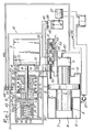
- FIG. 1 we see a direct-acting free-piston motor-compressor designated by the general reference 1 and comprising a movable assembly 2.
- the driving piston 3 evolves in the combustion chamber 4 while the piston 5 of the compressor moves in the chamber 6.
- An intermediate piston 7 moves, on the one hand, in the chamber 8 and thus constitutes a scanning pump communicating with the scanning chamber 9, on the other hand, in the mattress chamber 10.
- the moving assembly 2 When stationary, and as shown in the drawing, the moving assembly 2 is in an intermediate position between the neutral position "UP" on the left of the figure and the neutral position "LOW".
- the starting device essentially comprises a starting tank 11 capable of being filled with compressed air by an independent compressor which will be described later, and a set, designated by the general reference 12, of two valves arranged between the tank 11 and the mattress chamber 10.
- At least one wall 13 is disposed transversely to the conduit connecting the reservoir 11 and the mattress chamber 10. It has an orifice 14 which can be closed by the head of one or the other valve of the assembly 12 and the edges of this orifice 14, on either side of. the wall 13, are shaped as a valve seat 15 and 16.
- a first valve called the opening valve, comprises a head 17 mounted on a rod 18 passing through the orifice 14. The end. mity of the rod 18 is linked to a piston 19 evolving in a chamber 20 and thus constituting a control cylinder.
- a second valve called a shut-off valve, has a head 21 mounted on a rod 22, the end of which is open in the form of a cup 23.
- the two valves are coaxial, the rod 18 of the opening valve sliding in the hollow rod 22 of the closing valve, the rod 22 being itself guided in a shoulder 24 of the casing of the device.
- a first spring 25 is supported on the opposite faces of the piston 19 and the cup 23, while a second spring 26, the stiffness of which is significantly greater than that of the spring 25, is supported on the cup 23, on the opposite side to the spring 25 and on the shoulder 24.
- the closing valve 21 is held in the open position by its spring 26, while the opening valve 17 is supported on its seat 15 under the action of the spring 25.
- the dimensions of the rods 18 and 22 of the valves are such that a certain distance 1. 1 exists at rest between the piston 19 and the cup 23.
- a damping washer 27 On the other hand on one or the other of the opposite faces of the piston 19 and of the cup 23 is mounted a damping washer 27 whose utility will appear later.
- the chamber 20 of the control jack is capable of being placed in communication with a control tank 28 by means of a calibrated orifice 29.
- the latter is normally closed by a shutter 30 held on its seat 31 by a spring 32
- the shutter 30 is however shaped so that it constitutes a piston capable of pushing the spring 32 under the action of the air pressure in the control tank 28.
- the shutter 30 has example a shoulder 33 but it is obvious that any other equivalent arrangement could be provided.
- the shutter 30 preferably has an orifice 34 s - capable of being closed by a fixed needle 35 when the shutter leaves its seat 31.
- the needle 35 also constitutes a stop limiting the opening movement of the shutter 30.
- the start-up 11 and control tanks 28 are filled by an independent air compressor 36 driven, for example by an electric motor 37.
- the discharge pipe 38 of the compressor 36 communicates directly, via the pipe 39, with the tank 11 and, by means of a non-return valve 40, disposed between the pipes 41 and 42, with the reservoir 28.
- a non-return valve 40 disposed between the pipes 41 and 42, with the reservoir 28.
- the latter will also be in communication, via the pipes 43 and 44 and the valves non-return 45 and 46, respectively with the mattress chamber 10 and with the discharge duct 47 of the compressor 5-6.
- the suction duct 48 of the independent compressor 36 is connected to the central chamber 49 of a slide distributor 50.
- the latter is subjected to the action of a spring 51 which normally keeps it in abutment to the left of the figure in a fixed position such that the central chamber 49 communicates with the mattress chamber 10 via the pipe 52.
- the drawer 50 however has an extension 53 (or is coupled to an equivalent member) penetrating into the mattress chamber 10 and capable of be operated by the equi mobile page 2, under conditions which will be indicated below to move the drawer 50 to the right of the figure.
- the central chamber 49 comes into communication with the atmosphere via the pipe 54.
- the left end of the drawer 50 finally constitutes a jack supplied by the pipe 55 in communication with the control tank 28 via the pipe 42. This is also connected to the control members (not shown) of the motor 1.
- the electric circuit of the motor 37 advantageously comprises, in addition to a general switch 56, a manostatic switch 57 controlled, in the direction of opening of the circuit, by the pressure in the scanning chamber 9 of the motor 1.
- the motor 1 and the various organs of its starting device being in the positions shown in FIG. 1, the main switch 56 is closed to operate the compressor 37.
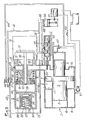
- the suction duct 48 being connected to the mattress chamber 10, the latter empties of the air it contained and the moving assembly 2 moves to the right of FIG. 1 until it reaches the position shown in FIG. 2.
- the drawer 50 is pushed back to the right and the suction duct 48 is then placed in communication with the atmosphere by the chamber 49 and the pipe 54.
- the air sucked into the mattress chamber 10 and then to the atmosphere 28 is discharged by the compressor 36, on the one hand towards the starting tank 11, on the other hand towards the control tank 28.
- the air pressure increases in each of these two tanks. It will be noted here that any air leaks between the shutter 30 and its seat 31 will be evacuated to the atmosphere through the orifice 34 without this resulting in an annoying movement of the shutter 30 against the action of its spring 32.
- the orifice 34 ensures complete discharge of the control cylinder 19-20 and prevents any displacement of the opening valve 17.
- the opening of the valve 17 is all the more rapid as soon as the lifting of the head, the pressures on the two faces of it are balanced.
- the stroke of the jack 19 continues over the distance L I until it comes to bear on the damping washer 27 of the cup 23.
- the jack 19, bearing on the cup 23, causes the displacement to the right, following a stroke L 2 , of the valve 21 which abruptly applies on its seat 16 and close the orifice 14.
- the pressure is maintained in the chamber 20 and the various members remain in the positions shown in FIG. 3, since the compressor 37 continues to fill the control reservoir 28.
- control shutter 30 it may in fact be advantageous to modify the initial compression of the spring 32, in particular as a function of the ambient temperature.
- a movable stop 58 connected to the housing by a deformable waterproof sleeve 59, filled with a thermostatic fluid.
- the deformation of the sleeve 59 is opposed to a spring 60, the compression of which is adjustable by means of a screw 61.
Landscapes
- Engineering & Computer Science (AREA)
- Chemical & Material Sciences (AREA)
- Combustion & Propulsion (AREA)
- Mechanical Engineering (AREA)
- General Engineering & Computer Science (AREA)
- Valve Device For Special Equipments (AREA)
- Control Of Throttle Valves Provided In The Intake System Or In The Exhaust System (AREA)
Applications Claiming Priority (2)
| Application Number | Priority Date | Filing Date | Title |
|---|---|---|---|
| FR8400082A FR2557633B1 (fr) | 1984-01-04 | 1984-01-04 | Dispositif de demarrage pour moteur a combustion interne, en particulier pour moteur a piston libre |
| FR8400082 | 1984-01-04 |
Publications (2)
| Publication Number | Publication Date |
|---|---|
| EP0148078A2 true EP0148078A2 (de) | 1985-07-10 |
| EP0148078A3 EP0148078A3 (de) | 1985-08-28 |
Family
ID=9299833
Family Applications (1)
| Application Number | Title | Priority Date | Filing Date |
|---|---|---|---|
| EP84402673A Withdrawn EP0148078A3 (de) | 1984-01-04 | 1984-12-20 | Anlassvorrichtung für eine Brennkraftmaschine inbesondere für eine Freikolbenmaschine |
Country Status (2)
| Country | Link |
|---|---|
| EP (1) | EP0148078A3 (de) |
| FR (1) | FR2557633B1 (de) |
Cited By (2)
| Publication number | Priority date | Publication date | Assignee | Title |
|---|---|---|---|---|
| WO1990015231A1 (de) * | 1989-06-08 | 1990-12-13 | Frank Stelzer | Anlasser für einen einen freifliegenden stufenkolben aufweisenden motor |
| FR2660969A1 (fr) * | 1990-04-12 | 1991-10-18 | Minoru Rech Avancee I | Systeme de moteur a piston libre. |
Family Cites Families (5)
| Publication number | Priority date | Publication date | Assignee | Title |
|---|---|---|---|---|
| DE754701C (de) * | 1942-11-21 | 1954-08-16 | Messerschmitt Boelkow Blohm | Verfahren und Vorrichtung zur Vermeidung der schaedlichen physikalischen und chemischen Einwirkungen von Pulver-verbrennungsrueckstaenden auf die Wandungen der Druckgas-kammern von Druckgasanlassern fuer Brennkraftmaschinen |
| FR1001194A (fr) * | 1946-03-22 | 1952-02-20 | Soc Es Energie Sa | Perfectionnements apportés aux dispositifs de démarrage pneumatique, notamment pour les machines à pistons libres |
| FR1048425A (fr) * | 1950-09-09 | 1953-12-22 | Soupape à double fermeture et en particulier soupape à fermeture rapide | |
| FR1439104A (fr) * | 1965-03-23 | 1966-05-20 | Anciens Etablissements Panhard | Perfectionnements apportés aux dispositifs de mise en marche des moteurs monocylindriques à piston libre à double effet |
| FR2264184A1 (en) * | 1974-03-15 | 1975-10-10 | Moiroux Auguste | Starting device for free piston engine - uses slide valve to reduce and then increase pressure of air cushion |
-
1984
- 1984-01-04 FR FR8400082A patent/FR2557633B1/fr not_active Expired
- 1984-12-20 EP EP84402673A patent/EP0148078A3/de not_active Withdrawn
Cited By (2)
| Publication number | Priority date | Publication date | Assignee | Title |
|---|---|---|---|---|
| WO1990015231A1 (de) * | 1989-06-08 | 1990-12-13 | Frank Stelzer | Anlasser für einen einen freifliegenden stufenkolben aufweisenden motor |
| FR2660969A1 (fr) * | 1990-04-12 | 1991-10-18 | Minoru Rech Avancee I | Systeme de moteur a piston libre. |
Also Published As
| Publication number | Publication date |
|---|---|
| EP0148078A3 (de) | 1985-08-28 |
| FR2557633B1 (fr) | 1986-05-30 |
| FR2557633A1 (fr) | 1985-07-05 |
Similar Documents
| Publication | Publication Date | Title |
|---|---|---|
| EP1341992B1 (de) | Vorrichtung zum betätigen der ventile und steuerungsverfahren dafür | |
| FR2470267A1 (fr) | Compresseur a piston roulant | |
| FR2547866A1 (fr) | Appareil de commande du dispositif d'echappement d'un moteur a combustion interne | |
| CH639004A5 (fr) | Dispositif de commande d'un sechoir d'air comprime. | |
| FR2638494A1 (fr) | Pompe entrainee pneumatiquement | |
| FR2492886A1 (fr) | Appareil de commande detecteur d'altitude | |
| FR2673246A1 (fr) | Dispositif d'injection de liquide, notamment de combustible, dans au moins une chambre pressurisee d'une machine a fonctionnement periodique tel que moteur a combustion interne et moteur de ce type equipe de ce dispositif. | |
| FR2461821A1 (fr) | Dispositif a depression de commande du volet de depart d'un carburateur de moteur a combustion interne | |
| FR2786238A1 (fr) | Dispositif d'actionnement pour un embrayage a friction | |
| FR2596805A1 (fr) | Dispositif de reglage du debut de l'injection dans une pompe d'injection de carburant avec avance du debut d'injection | |
| EP0786045B1 (de) | Zweitaktmotor mit verbesserter einspritzanordnung und verfahren zu deren einspritzung | |
| EP0040121B1 (de) | Vorrichtung zum Abschalten eines Ventilfallhebers | |
| FR2720159A1 (fr) | Procédé et dispositif pour l'estimation de la poussée d'un statoréacteur. | |
| EP0148078A2 (de) | Anlassvorrichtung für eine Brennkraftmaschine inbesondere für eine Freikolbenmaschine | |
| FR2714018A1 (fr) | Dispositif de propulsion de navire. | |
| FR2468771A1 (fr) | Dispositif de commande d'aspiration pour un compresseur | |
| FR2529616A1 (fr) | Systeme de rappel pneumatique de soupape pour moteur a combustion interne | |
| FR2771696A1 (fr) | Servofrein a augmentation de signal de sortie sans changement de force de pedale de frein | |
| FR2662214A1 (fr) | Moteur a deux temps a injection pneumatique de carburant et a commande d'injection par un boisseau rotatif. | |
| EP1132581A1 (de) | Elektromagnetventil mit Pneumatikfeder und Kniehebelmechanismus | |
| EP1236869A1 (de) | Anordnung zum Einbringen des Kraftstoff-Luft-Gemisches in eine Brennkammer, insbesondere für eine Zweitaktbrennkraftmaschine | |
| WO1999000285A1 (fr) | Maitre-cylindre a reaction hydraulique dynamique et a piston flottant | |
| FR2803882A1 (fr) | Systeme de moteur hors bord | |
| EP0092469B1 (de) | Entlüftungsvorrichtung für Zylinder-Kolbenanordnung und Radbremszylinder mit solcher Vorrichtung | |
| FR2479341A1 (fr) | Pompe d'injection de carburant munie d'un dispositif de reglage d'avance a l'injection |
Legal Events
| Date | Code | Title | Description |
|---|---|---|---|
| PUAI | Public reference made under article 153(3) epc to a published international application that has entered the european phase |
Free format text: ORIGINAL CODE: 0009012 |
|
| PUAL | Search report despatched |
Free format text: ORIGINAL CODE: 0009013 |
|
| AK | Designated contracting states |
Designated state(s): CH DE GB IT LI NL SE |
|
| AK | Designated contracting states |
Designated state(s): CH DE GB IT LI NL SE |
|
| STAA | Information on the status of an ep patent application or granted ep patent |
Free format text: STATUS: THE APPLICATION HAS BEEN WITHDRAWN |
|
| 18W | Application withdrawn |
Withdrawal date: 19860203 |
|
| RIN1 | Information on inventor provided before grant (corrected) |
Inventor name: MOIROUX, AUGUSTE |