EP0148109B1 - Pile-driving apparatus and method of operating such apparatus - Google Patents
Pile-driving apparatus and method of operating such apparatus Download PDFInfo
- Publication number
- EP0148109B1 EP0148109B1 EP84630220A EP84630220A EP0148109B1 EP 0148109 B1 EP0148109 B1 EP 0148109B1 EP 84630220 A EP84630220 A EP 84630220A EP 84630220 A EP84630220 A EP 84630220A EP 0148109 B1 EP0148109 B1 EP 0148109B1
- Authority
- EP
- European Patent Office
- Prior art keywords
- timer
- sensing
- drive
- take
- drop hammer
- Prior art date
- Legal status (The legal status is an assumption and is not a legal conclusion. Google has not performed a legal analysis and makes no representation as to the accuracy of the status listed.)
- Expired
Links
- 238000000034 method Methods 0.000 title claims abstract description 10
- 230000001960 triggered effect Effects 0.000 claims abstract description 14
- 230000004044 response Effects 0.000 claims description 22
- 239000012530 fluid Substances 0.000 claims description 6
- 239000004020 conductor Substances 0.000 claims description 5
- 230000001934 delay Effects 0.000 claims 1
- QSHDDOUJBYECFT-UHFFFAOYSA-N mercury Chemical compound [Hg] QSHDDOUJBYECFT-UHFFFAOYSA-N 0.000 abstract description 6
- 229910052753 mercury Inorganic materials 0.000 abstract description 6
- 230000008569 process Effects 0.000 abstract description 2
- 238000004458 analytical method Methods 0.000 description 5
- 230000007246 mechanism Effects 0.000 description 3
- 229910000831 Steel Inorganic materials 0.000 description 2
- 238000010586 diagram Methods 0.000 description 2
- 230000007257 malfunction Effects 0.000 description 2
- 239000002689 soil Substances 0.000 description 2
- 239000010959 steel Substances 0.000 description 2
- 239000004677 Nylon Substances 0.000 description 1
- 230000015556 catabolic process Effects 0.000 description 1
- 230000008859 change Effects 0.000 description 1
- 238000010276 construction Methods 0.000 description 1
- 238000006073 displacement reaction Methods 0.000 description 1
- 230000000694 effects Effects 0.000 description 1
- 239000012777 electrically insulating material Substances 0.000 description 1
- 238000000605 extraction Methods 0.000 description 1
- 230000004048 modification Effects 0.000 description 1
- 238000012986 modification Methods 0.000 description 1
- 229920001778 nylon Polymers 0.000 description 1
- 230000001681 protective effect Effects 0.000 description 1
- 230000035939 shock Effects 0.000 description 1
- 238000003466 welding Methods 0.000 description 1
Images

Classifications
-
- E—FIXED CONSTRUCTIONS
- E02—HYDRAULIC ENGINEERING; FOUNDATIONS; SOIL SHIFTING
- E02D—FOUNDATIONS; EXCAVATIONS; EMBANKMENTS; UNDERGROUND OR UNDERWATER STRUCTURES
- E02D7/00—Methods or apparatus for placing sheet pile bulkheads, piles, mouldpipes, or other moulds
- E02D7/02—Placing by driving
- E02D7/06—Power-driven drivers
- E02D7/08—Drop drivers with free-falling hammer
Definitions
- This invention relates to pile-driving apparatus and to a method of operating such apparatus.
- pile-driving apparatus comprising a drop hammer for imparting blows to a pile, and a winch for lifting the drop hammer between successive blows.
- the winch comprises a winch drive, a winch drum, clutch means for disengageably engaging the winch drive with the winch drum, and a rope connecting the drop hammer to the winch drum, the rope passing over a sheeve.
- Sensing means is provided for sensing the load applied by the rope to the sheeve, and the output of the load sensitive means is fed to an analysis device.
- the analysis device is able to detect the moment of impact of the drop hammer on the pile, and provides an output causing the clutch to engage and the drop hammer therefore to be lifted.
- the winch drum is provided with marks, and fixed detectors are provided which are able to detect the direction of rotation and the angular position of the drum.
- the output of the detectors is fed to the analysis device which then provides a further signal to disengage the clutch when the drop hammer has reached a certain height. In this manner automatic operation of the pile driving apparatus is achieved.
- the location of the load sensing means on what appears to be the mountings of the sheeve would require expensive modification of existing pile-driving apparatus. Furthermore, the location of the load sensing means at this critical point of the pile-driving apparatus can lead to long and costly breakdowns. Also, as will be apparent from the waveforms illustrated in Figures 2 and 3 of that specification, and by the fact that both the degree and direction of rotation displacement of the winch drum need to be detected, the analysis device will, of necessity, have to be of a complex nature, able to perform complex analyses, and, because of its complexity, be prone to malfunction.
- a further pile-driving apparatus is described in FR-A-1 100 681, this apparatus having a means for sensing the change in tension of the hammer supporting cable upon impact, the sensing means being connected to a valve to effect raising once more of the hammer.
- pile-driving apparatus comprising a drop hammer for imparting blows to an object; hoisting means for lifting the hammer away from the object between successive blows, the hoisting means comprising a rope or cable connected to the drop hammer, take-up means for taking up the rope or cable, drive means, and disengageable drive engagement means for disengageably engaging the drive means with the take-up means; sensing means for sensing the delivery of a blow, the drive engagement means being operative in response to the sensing means to engage the drive means with the take-up means in response to said sensing; characterised in that it further comprises a timer operative in response to the sensing means to be triggered in response to said sensing, the drive engagement means being operative in response to the timer to disengage the drive means from the take-up means a predetermined time interval after the timer is triggered; and in that the sensing means is impact sensitive sensing means mounted on the drop hammer or on the object receiving the blow.
- the timer may be adjustable, so as to permit adjustment of said predetermined time interval.
- the sensing means may comprise a container containing an electrically conductive fluid such as, for example, mercury and having a pair of conductor terminals exposed to the fluid, the fluid being displaceable in the container to make or break electrical contact between the conductor terminals.
- an electrically conductive fluid such as, for example, mercury
- the sensing means may be mounted on a driven object to which said blows are imparted.
- Said timer may be a first timer, there being provided a second timer for providing a predetermined time delay, less than said predetermined time interval, between the time of said sensing and engagement of the drive engagement means.
- Said second timer may be adjustable, so as to permit adjustment of said predetermined time delay.
- the apparatus may further comprise brake means for braking the take-up means, the brake means being operative in response to the second timer to brake the take-up means for at least part of the duration of said predetermined time delay.
- a method of operating pile-driving apparatus comprising a drop hammer for imparting blows to an object; hoisting means for lifing the hammer away from the object between successive blows, the hoisting means comprising a rope or cable connected to the drop hammer,' take-up means for taking up the rope or cable,.
- drive means, and disengageable drive engagement means for disengageably engaging the drive means with the take-up means; and sensing means for sensing the delivery of a blow, the drive engagement means being operative in response to the sensing means to engage the drive means with the take-up means in response to said sensing;
- the timer may be a first timer, there being a second timer which is triggered in response to said sensing, the second timer delaying engagement of the drive engagement means for a predetermined time delay, less than said predetermined time interval, from the time of said sensing.
- the take-up means may be braked for at least part of the duration of said time delay.
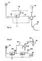
- reference numeral 10 generally indicates pile-driving apparatus comprising a drop hammer 12 and hoisting means in the form of a winch 14 for lifting the drop hammer.
- the drop hammer is connected to the winch by means of a wire rope 16 which passes over a sheave 18 forming part of the apparatus.
- Reference numeral 20 indicates a pile which is being driven into the ground by the apparatus 10.
- a protective helmet 22 fits over the upper end of the pile.
- the winch 14 comprises a winch drive 24, a winch drum 26, and a pneumatically operated clutch 28 for disengageably engaging the winch drive with the winch drum.
- the apparatus 10 further comprises sensing means in the form of an impact sensitive sensor 34 (Figure 2) located in a steel casing 36, the steel casing being detachably secured, e.g. by means of a strap, to the pile 20. It could, alternatively, be secured permanently to the helmet 22, such as by welding.
- the sensor 34 is connected to a control device 38, the control device having an electrical output which is connected to the solenoid-operated valve 32.
- the impact sensitive sensor 34 comprises a container 40 of an electrically insulating material such as Nylon, the container containing a quantity of mercury 42 and having a pair of conductor terminals 44 exposed to the mercury.
- the sensor 34 will normally be in the condition illustrated in Figure 2, i.e. with the mercury 42 bridging the terminals 44.
- the mercury 42 Upon receiving an impact, however, the mercury 42 will temporarily be displaced away from the terminals 44, causing a temporary open circuit.
- the control device 38 comprises an electrical timer 46 having the sensor 34 connected to its trigger 48.
- the timer is designed to produce an output voltage on its output terminal 50 for a predetermined time interval after being triggered, the time interval being adjustable by means of a variable resistor 52.
- the design of such a timer will be well within the capabilities of a skilled artisan and will therefore not be described in detail. It could, for example, include an integrated circuit known as a 555 timer connected in a monostable or "one- shot" configuration.
- Operation of the apparatus 10 is as follows. Normally, the solenoid operated valve 32 is closed and the clutch 28 thus disengaged. To start the apparatus, the valve 32 is opened manually, admitting compressed air to the clutch 28 and thus causing the clutch to engage. This results in drive being transmitted from the winch drive 24 to the winch drum 26, causing the drop hammer 12 to be lifted. When the drop hammer has been lifted to the desired height, the valve 32 is released, causing the clutch 28 to disengage. The drop hammer 12 now falls freely, unwinding the drum 26. The impact resulting from the drop hammer hitting the helmet 22 is sensed by the sensor 34, triggering the timer 46.
- the solenoid operated valve 32 is switched over to manual operation.
- the clutch may be such that it is spring biased towards the engaged condition, the admission of compressed air being effective to disengage the clutch. Operation of the timer 46 and the solenoid-operated valve 32 will then be such that, upon triggering of the timer, the valve is closed and compressed air exhausted from the clutch operating mechanism. In this manner the response of the clutch can be speeded up as compressed air can normally be exhausted from the clutch operating mechanism much faster than it is possible to admit compressed air to the mechanism.
- control device 38 may, for example, comprise an audible alarm which is activated should the terminals of the sensor 34, due to malfunction, not be bridged again within a predetermined time interval after opening.
- the apparatus can be used to impart a vibratory force to a pile such as during extraction of a pile casing or for consolidating a concrete filling in such a casing. It will furthermore be appreciated that the apparatus could be used to compact soil, in which event the drop hammer 12 will be arranged to impart blows directly to the soil, the sensor 34 being mounted on the drop hammer.
- FIG 4 there is shown part of a control device 38.1 according to another embodiment of the invention. That part not shown in Figure 4 is identical to the device shown in Figure 3.
- the timer 46 of Figure 3 is replaced by two timers 54.1 and 54.2, each being individually adjustable by variable resistors 56.1 and 56.2 respectively.
- the timers 54.1 and 54.2 are connected in series such that the first timer 54.1 is triggered in response to the sensor 34, to provide a time delay, the second timer 54.2 being triggered when the first timer has reached the end of the time delay.
- a pneumatically operated brake 60 may be provided for the winch drum 26.
- the brake 60 is connected to the air receiver 30 via a solenoid operated valve 62, the valve 62 being operated by the output of the first timer 54.1.
- the drum 26 will be braked for the duration of the time delay provided by the first timer 54.1, thus preventing undue shock loads in the rope 16 resulting from the winch drum continuing to unwind subsequent to the point of impact and the slack in the rope being taken up again when the clutch engages.
Landscapes
- Engineering & Computer Science (AREA)
- Life Sciences & Earth Sciences (AREA)
- General Life Sciences & Earth Sciences (AREA)
- Mining & Mineral Resources (AREA)
- Paleontology (AREA)
- Civil Engineering (AREA)
- General Engineering & Computer Science (AREA)
- Structural Engineering (AREA)
- Placing Or Removing Of Piles Or Sheet Piles, Or Accessories Thereof (AREA)
- Processing And Handling Of Plastics And Other Materials For Molding In General (AREA)
- Vehicle Body Suspensions (AREA)
- Chairs Characterized By Structure (AREA)
Priority Applications (1)
| Application Number | Priority Date | Filing Date | Title |
|---|---|---|---|
| AT84630220T ATE41185T1 (de) | 1983-12-29 | 1984-12-28 | Pfahlrammvorrichtung und verfahren zur betaetigung einer derartigen vorrichtung. |
Applications Claiming Priority (2)
| Application Number | Priority Date | Filing Date | Title |
|---|---|---|---|
| ZA839709 | 1983-12-29 | ||
| ZA839709 | 1983-12-29 |
Publications (3)
| Publication Number | Publication Date |
|---|---|
| EP0148109A2 EP0148109A2 (en) | 1985-07-10 |
| EP0148109A3 EP0148109A3 (en) | 1986-05-28 |
| EP0148109B1 true EP0148109B1 (en) | 1989-03-08 |
Family
ID=25577070
Family Applications (1)
| Application Number | Title | Priority Date | Filing Date |
|---|---|---|---|
| EP84630220A Expired EP0148109B1 (en) | 1983-12-29 | 1984-12-28 | Pile-driving apparatus and method of operating such apparatus |
Country Status (9)
| Country | Link |
|---|---|
| US (1) | US4660655A (da) |
| EP (1) | EP0148109B1 (da) |
| JP (1) | JPS60156823A (da) |
| AT (1) | ATE41185T1 (da) |
| AU (1) | AU575609B2 (da) |
| BR (1) | BR8406784A (da) |
| CA (1) | CA1211632A (da) |
| DE (1) | DE3477025D1 (da) |
| DK (1) | DK620184A (da) |
Families Citing this family (11)
| Publication number | Priority date | Publication date | Assignee | Title |
|---|---|---|---|---|
| US4802538A (en) * | 1986-02-20 | 1989-02-07 | Brian Hays | Piling hammer |
| DE3710253A1 (de) * | 1987-03-28 | 1988-10-13 | Nordmeyer Kg | Seilwinde fuer wahlweisen hub-, senk- und zyklischen freifall-schlagbetrieb |
| US4977965A (en) * | 1989-08-04 | 1990-12-18 | Rupe Robert E | Automatic drop hammer system |
| CA2270856C (en) | 1999-05-05 | 2002-08-27 | James Fehr | Flow restrictor valve for a downhole drilling assembly |
| US7404449B2 (en) * | 2003-05-12 | 2008-07-29 | Bermingham Construction Limited | Pile driving control apparatus and pile driving system |
| CA2466862C (en) * | 2003-05-12 | 2011-07-26 | Bermingham Construction Limited | Pile driver with energy monitoring and control circuit |
| CN105264144A (zh) * | 2013-04-19 | 2016-01-20 | 弗拉克图姆2012公司 | 锤击装置和用于操作锤击装置的方法 |
| MY190434A (en) * | 2015-10-12 | 2022-04-21 | Yeow Thium Chin | Apparatus and method for pile set measurement |
| DE102016008819A1 (de) * | 2016-07-19 | 2018-01-25 | Liebherr-Werk Nenzing Gmbh | Schlagzahloptimierung |
| DE102016011352A1 (de) * | 2016-09-20 | 2018-03-22 | Liebherr-Werk Nenzing Gmbh | Verfahren zur Steuerung eines Freifallhammers |
| SG11202108277PA (en) * | 2019-02-12 | 2021-08-30 | Jia Yi Chin | Pile set measurement apparatus |
Family Cites Families (20)
| Publication number | Priority date | Publication date | Assignee | Title |
|---|---|---|---|---|
| NL57765C (da) * | 1900-01-01 | |||
| GB209351A (en) * | 1923-04-16 | 1924-01-10 | Marcus Bernard Behrman | Improvements in or relating to cheque protectors |
| US2214197A (en) * | 1938-08-23 | 1940-09-10 | John M Jackson | Mercury switch |
| FR1100681A (fr) * | 1953-05-16 | 1955-09-22 | Westinghouse Bremsen Gmbh | Contrôle d'appareils agissant par la chute d'un poids, par exemple de moutons |
| GB983403A (en) * | 1960-06-11 | 1965-02-17 | Eumuco Ag Fur Maschb | Forging hammer |
| SU468685A1 (ru) * | 1966-05-28 | 1975-04-30 | Ступинский металлургический комбинат | Пресс-молот |
| GB1234164A (da) * | 1968-03-20 | 1971-06-03 | ||
| GB1261220A (en) * | 1969-03-11 | 1972-01-26 | British Steel Piling Co Ltd | Improvements in or relating to drop hammers |
| SE341669B (da) * | 1970-04-13 | 1972-01-10 | Stabilator Ab | |
| GB1294915A (da) * | 1970-06-24 | 1972-11-01 | ||
| US3721095A (en) * | 1971-08-23 | 1973-03-20 | Bolt Associates Inc | Controllable force method and system of driving piles |
| GB1452067A (en) * | 1972-11-16 | 1976-10-06 | Hunt Bros Oldbruy | Drop-hammers |
| US3938595A (en) * | 1974-09-19 | 1976-02-17 | Raymond International, Inc. | Apparatus and method for driving bulb piles |
| US4002211A (en) * | 1974-09-19 | 1977-01-11 | Raymond International Inc. | Cable operated apparatus for forming piles |
| US4099040A (en) * | 1976-03-30 | 1978-07-04 | Fifth Dimension, Inc. | Mercury type tilt switch |
| GB1572349A (en) * | 1976-05-21 | 1980-07-30 | Bsp Int Foundation | Drop hammers |
| FR2369908A1 (fr) * | 1976-11-08 | 1978-06-02 | Montabert Roger | Appareil a percussions hydraulique |
| GB1595416A (en) * | 1978-03-22 | 1981-08-12 | Anslow Ltd | Control of an hydraulic coining press |
| AU546771B2 (en) * | 1981-02-19 | 1985-09-19 | Compagnie Internationale Des Pieux Armes Frankignoul S.A. | Pile driver |
| US4493956A (en) * | 1983-08-29 | 1985-01-15 | Yeoman Richard E | Impact switch |
-
1984
- 1984-12-21 DK DK620184A patent/DK620184A/da not_active Application Discontinuation
- 1984-12-27 JP JP59282035A patent/JPS60156823A/ja active Pending
- 1984-12-27 AU AU37145/84A patent/AU575609B2/en not_active Ceased
- 1984-12-28 CA CA000471198A patent/CA1211632A/en not_active Expired
- 1984-12-28 DE DE8484630220T patent/DE3477025D1/de not_active Expired
- 1984-12-28 BR BR8406784A patent/BR8406784A/pt unknown
- 1984-12-28 EP EP84630220A patent/EP0148109B1/en not_active Expired
- 1984-12-28 AT AT84630220T patent/ATE41185T1/de not_active IP Right Cessation
- 1984-12-28 US US06/687,175 patent/US4660655A/en not_active Expired - Fee Related
Also Published As
| Publication number | Publication date |
|---|---|
| CA1211632A (en) | 1986-09-23 |
| BR8406784A (pt) | 1985-10-22 |
| DK620184A (da) | 1985-06-30 |
| DK620184D0 (da) | 1984-12-21 |
| EP0148109A3 (en) | 1986-05-28 |
| DE3477025D1 (en) | 1989-04-13 |
| AU3714584A (en) | 1985-07-04 |
| EP0148109A2 (en) | 1985-07-10 |
| ATE41185T1 (de) | 1989-03-15 |
| JPS60156823A (ja) | 1985-08-17 |
| US4660655A (en) | 1987-04-28 |
| AU575609B2 (en) | 1988-08-04 |
Similar Documents
| Publication | Publication Date | Title |
|---|---|---|
| US4660655A (en) | Pile-driving apparatus and method of operating such apparatus | |
| EP1190980B1 (en) | Method for controlling crane brake operation | |
| CN102348627B (zh) | 电磁式安全设备触发器 | |
| US5578801A (en) | Apparatus and method for sensing slippage of elevator drive cable over a traction sheave | |
| CN102348626B (zh) | 电梯过加速和过速保护系统 | |
| US4324385A (en) | Device for removing and depositing loads between two supports in repeated relative vertical movement | |
| US3938595A (en) | Apparatus and method for driving bulb piles | |
| EP0068683A1 (en) | Slack rope detecting apparatus | |
| EP0841298B1 (de) | Steuerungsanordnung mit Erkennung des Gewichts der Last | |
| CA2727040A1 (en) | Method of controlling rotation speed of motor of speed-controllable hoist drive, and hoist drive | |
| US2704401A (en) | Stock line recorders | |
| US5402863A (en) | Apparatus to automatically adjust spring tension of an elevator brake to maintain brake torque | |
| GB2148227A (en) | Overhoist prevention system | |
| EP1783085A1 (en) | Elevator apparatus | |
| US5415053A (en) | Apparatus for automatically testing machine safety system | |
| JPS598996Y2 (ja) | 多点同時サウンジング装置 | |
| KR100471418B1 (ko) | 권양기의 밸런스 제어장치 | |
| JPH0618220Y2 (ja) | アーク炉における電極昇降用マストの落下防止装置 | |
| US4531630A (en) | Load sensor | |
| EP0404271B1 (en) | Hose breakage safety system | |
| JPH1161894A (ja) | 水道管打ち込み機 | |
| SU905181A1 (ru) | Система обеспечени аварийного останова грузоподъемной машины | |
| SU897682A1 (ru) | Шахтна подъемна установка | |
| SU1063759A1 (ru) | Устройство дл контрол проскальзывани каната подъемника по шкиву | |
| US1856897A (en) | Stock line recorder |
Legal Events
| Date | Code | Title | Description |
|---|---|---|---|
| PUAI | Public reference made under article 153(3) epc to a published international application that has entered the european phase |
Free format text: ORIGINAL CODE: 0009012 |
|
| AK | Designated contracting states |
Designated state(s): AT BE CH DE FR GB IT LI LU NL SE |
|
| PUAL | Search report despatched |
Free format text: ORIGINAL CODE: 0009013 |
|
| AK | Designated contracting states |
Kind code of ref document: A3 Designated state(s): AT BE CH DE FR GB IT LI LU NL SE |
|
| 17P | Request for examination filed |
Effective date: 19861121 |
|
| 17Q | First examination report despatched |
Effective date: 19880202 |
|
| GRAA | (expected) grant |
Free format text: ORIGINAL CODE: 0009210 |
|
| AK | Designated contracting states |
Kind code of ref document: B1 Designated state(s): AT BE CH DE FR GB IT LI LU NL SE |
|
| REF | Corresponds to: |
Ref document number: 41185 Country of ref document: AT Date of ref document: 19890315 Kind code of ref document: T |
|
| REF | Corresponds to: |
Ref document number: 3477025 Country of ref document: DE Date of ref document: 19890413 |
|
| ITF | It: translation for a ep patent filed | ||
| ET | Fr: translation filed | ||
| PGFP | Annual fee paid to national office [announced via postgrant information from national office to epo] |
Ref country code: FR Payment date: 19891222 Year of fee payment: 6 |
|
| PGFP | Annual fee paid to national office [announced via postgrant information from national office to epo] |
Ref country code: AT Payment date: 19891227 Year of fee payment: 6 |
|
| PGFP | Annual fee paid to national office [announced via postgrant information from national office to epo] |
Ref country code: LU Payment date: 19891229 Year of fee payment: 6 |
|
| ITTA | It: last paid annual fee | ||
| PG25 | Lapsed in a contracting state [announced via postgrant information from national office to epo] |
Ref country code: LU Free format text: LAPSE BECAUSE OF NON-PAYMENT OF DUE FEES Effective date: 19891231 |
|
| PGFP | Annual fee paid to national office [announced via postgrant information from national office to epo] |
Ref country code: NL Payment date: 19891231 Year of fee payment: 6 Ref country code: GB Payment date: 19891231 Year of fee payment: 6 |
|
| PGFP | Annual fee paid to national office [announced via postgrant information from national office to epo] |
Ref country code: CH Payment date: 19900103 Year of fee payment: 6 |
|
| PLBE | No opposition filed within time limit |
Free format text: ORIGINAL CODE: 0009261 |
|
| STAA | Information on the status of an ep patent application or granted ep patent |
Free format text: STATUS: NO OPPOSITION FILED WITHIN TIME LIMIT |
|
| PGFP | Annual fee paid to national office [announced via postgrant information from national office to epo] |
Ref country code: SE Payment date: 19900108 Year of fee payment: 6 |
|
| PGFP | Annual fee paid to national office [announced via postgrant information from national office to epo] |
Ref country code: BE Payment date: 19900109 Year of fee payment: 6 |
|
| PGFP | Annual fee paid to national office [announced via postgrant information from national office to epo] |
Ref country code: DE Payment date: 19900123 Year of fee payment: 6 |
|
| 26N | No opposition filed | ||
| PG25 | Lapsed in a contracting state [announced via postgrant information from national office to epo] |
Ref country code: GB Effective date: 19901228 Ref country code: AT Effective date: 19901228 |
|
| PG25 | Lapsed in a contracting state [announced via postgrant information from national office to epo] |
Ref country code: SE Effective date: 19901229 |
|
| PG25 | Lapsed in a contracting state [announced via postgrant information from national office to epo] |
Ref country code: LI Effective date: 19901231 Ref country code: CH Effective date: 19901231 Ref country code: BE Effective date: 19901231 |
|
| BERE | Be: lapsed |
Owner name: WILNER PIETER Effective date: 19901231 |
|
| PG25 | Lapsed in a contracting state [announced via postgrant information from national office to epo] |
Ref country code: NL Effective date: 19910701 |
|
| NLV4 | Nl: lapsed or anulled due to non-payment of the annual fee | ||
| GBPC | Gb: european patent ceased through non-payment of renewal fee | ||
| PG25 | Lapsed in a contracting state [announced via postgrant information from national office to epo] |
Ref country code: FR Effective date: 19910830 |
|
| REG | Reference to a national code |
Ref country code: CH Ref legal event code: PL |
|
| PG25 | Lapsed in a contracting state [announced via postgrant information from national office to epo] |
Ref country code: DE Effective date: 19910903 |
|
| REG | Reference to a national code |
Ref country code: FR Ref legal event code: ST |
|
| EUG | Se: european patent has lapsed |
Ref document number: 84630220.6 Effective date: 19910910 |