EP0148138A1 - Verfahren und Anordnung zum Eichen eines Positioniersystems - Google Patents
Verfahren und Anordnung zum Eichen eines Positioniersystems Download PDFInfo
- Publication number
- EP0148138A1 EP0148138A1 EP84850355A EP84850355A EP0148138A1 EP 0148138 A1 EP0148138 A1 EP 0148138A1 EP 84850355 A EP84850355 A EP 84850355A EP 84850355 A EP84850355 A EP 84850355A EP 0148138 A1 EP0148138 A1 EP 0148138A1
- Authority
- EP
- European Patent Office
- Prior art keywords
- positioning
- control means
- operating area
- detectors
- value signal
- Prior art date
- Legal status (The legal status is an assumption and is not a legal conclusion. Google has not performed a legal analysis and makes no representation as to the accuracy of the status listed.)
- Granted
Links
Images

Classifications
-
- G—PHYSICS
- G05—CONTROLLING; REGULATING
- G05D—SYSTEMS FOR CONTROLLING OR REGULATING NON-ELECTRIC VARIABLES
- G05D3/00—Control of position or direction
- G05D3/12—Control of position or direction using feedback
-
- G—PHYSICS
- G02—OPTICS
- G02B—OPTICAL ELEMENTS, SYSTEMS OR APPARATUS
- G02B26/00—Optical devices or arrangements for the control of light using movable or deformable optical elements
- G02B26/08—Optical devices or arrangements for the control of light using movable or deformable optical elements for controlling the direction of light
- G02B26/10—Scanning systems
- G02B26/101—Scanning systems with both horizontal and vertical deflecting means, e.g. raster or XY scanners
-
- G—PHYSICS
- G01—MEASURING; TESTING
- G01B—MEASURING LENGTH, THICKNESS OR SIMILAR LINEAR DIMENSIONS; MEASURING ANGLES; MEASURING AREAS; MEASURING IRREGULARITIES OF SURFACES OR CONTOURS
- G01B11/00—Measuring arrangements characterised by the use of optical techniques
-
- G—PHYSICS
- G02—OPTICS
- G02B—OPTICAL ELEMENTS, SYSTEMS OR APPARATUS
- G02B26/00—Optical devices or arrangements for the control of light using movable or deformable optical elements
- G02B26/08—Optical devices or arrangements for the control of light using movable or deformable optical elements for controlling the direction of light
- G02B26/10—Scanning systems
Definitions
- the present invention relates to a method of calibrating a positioning system which includes a control means sending command value signals to a positioning apparatus intended, during a working state, to locate an object in relation to an operating area, the location of the positioning apparatus being sensed and converted to an actual value signal, which is fed back to the control means.
- the invention also relates to the apparatus for carrying out the method.
- the control unit in a positioning system must be given information as to the actual position of the positioning apparatus in the system, for example where the light beam points in a pointing system.
- This information is provided by some form of transducer.
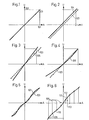
- Transducers have different types of deficiency, and the properties of a transducer can be assessed from a number of criteria. Some of these are dealt with below for an angular transducer which has an output voltage varying linearly with the torsional angle it registers. The criteria are illustrated in Figs. 1-5, where the torsional angle A is the coordinate on the horizontal axis 101, and the output signal voltage U the coordinate on the vertical axis 102.
- the function of a perfect transducer of this kind is given in Fig. 1 by the line (103), where where Kt is a constant depending on the type of transducer.
- the main object of the invention is to provide a method and an apparatus that will enable achieving good accuracy when using transducers having considerable linearity error, temperature drift and slow time- dependent drift.
- the sole demands made on the transducer in accordance with the invention is that it shall have good repeatability over a short time and that its linearity error will be small within small angular intervals.
- This object is realized in accordance with the method essentially in that detectors are placed within the operating area in given positions, and in that the working state of the positioning apparatus is interrupted by a calibration state at given time intervals, during the latter state the positioning apparatus being carefully aligned with at least one of the detectors, such that the output signal of the detector is allowed to activate the control means, whereafter the actual value signal is measured for calibrating the positioning apparatus in relation to the measured actual value signal.
- the apparatus according to the invention is substantially characterized in that detectors are arranged at given positions within the operating area, said detectors being connectable to the control unit, and that for given occasions the control means is adapted to put the object in register with at least one detector and to receive an output signal from the detector, and that for an optimum output signal from the detector the control means compares the actual value signal for the position of the object with information on the position of the detector, for calibrating the positioning apparatus.
- the invention primarily relates to systems where positioning is controlled by one or more galvanometers.
- Galvanometers are motors which rotate their shafts through a limited angle, e.g. 15°, in either direction.
- the galvanometer may be integrated with an angle transducer which must fulfill a number of conflicting requirements. This is due to the rapid angular movement of the galvanometer shaft.
- the moving part of this transmitter must therefore have low mass and must also withstand high speeds. To achieve an accuracy better than 0.1% over the entire operating area has so far required an advanced and therefore expensive implementation. In more sophisticated cases there is required, inter alia, a constant temperature in the whole of the structure on which the galvanometer is mounted.
- FIG. 7 illustrates the invention applied to a system with only one galvanometer for the sake of clarity, and although there is no great practical use for such a system it discloses the principle.
- a light source 201 sends a light beam 202 to a mirror 203 which is rotated by a galvanometer 204. The angular excursion of the mirror is sensed by the transducer 205. The beam is directed towards an operating area 206. In this, there are a number of holes 207, and under each of them there is a light-sensitive detector 208. These holes are part of one embodiment of the inventive apparatus, for which other embodiments are also possible.
- the control computer 209 sends commands to the galvanometer 204 and receives output signals from the transducer 205 and can also interpret the light intensity incident on the detectors 208. The appropriate detector is selected by the multiplexer 211.
- the angle 210 between the different detectors 207 as seen from the mirror 203 is assumed to be known.
- the control computer can calibrate the transducer 205 at suitable intervals by allowing the beam to scan the detectors 208. These are placed sufficiently closely for the linearity error of the transducer for the mentioned angle between the detectors to be small enough for achieving the desired accuracy. Calibration is performed often enough for ensuring that the transducer 205 will not drift between calibrations to an extent affecting accuracy more than can be accepted.
- the functional principle of the apparatus is depicted in Fig. 6.
- the angles between the detectors are known and are plotted as dots 108 in the Figure.
- the correct dots-109 may be plotted.
- a calibrated signal function 110 for the transducer may now be determined.
- the control computer evaluates an output signal 111 from the transducer 205 it can utilize the function 110 for calculating the angle 113 via the point 112.
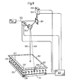
- Fig. 8 illustrates the inventive apparatus applied to a pointing system using two galvanometers.
- a light source 201 sends a beam to a mirror 203 which is rotated by a galvanometer 204.
- the angular position of the mirror is sensed by the transducer 205.
- the beam continues to a mirror 303 rotated by a galvanometer 304.
- the angular position of the mirror is sensed by a transducer 305.
- the beam has now been deflected towards a working surface which is restricted by a rectangular frame 501.
- a beam 502 is directed on to the working surface 501.
- the working state is interrupted at given intervals by a short calibrating state, a beam 503 for the latter state being illustrated in Fig. 8 by a dashed line.
- the beam will of course normally come from the same source 201.
- the galvanometer 204 then directs the beam just outside the working surface but within the operating range of the transducer 305.
- the control computer 209 now adjusts the galvanometers 204 and 304 so that the maximum output signal is obtained from the selected detector 308, whereby the computer reads the actual output signal from the transducer 305 in order to obtain the correct angular setting of the transducer. Afterwards, the system returns to the working state. In most cases such a calibrating state can be executed in 0.03 seconds.
- the embodiment with two galvanometers according to Fig. 8 differs insignificantly from the embodiment with one galvanometer. The difference is that there are approximately double as many detectors and that the control computer must also adjust the galvanometer which is not calibrated so that the beam impinges on the detectors.
- the utilisation of signals from the detectors is the same as what has been described for Fig. 6, apart from the fact that the same type of operation must be performed once for each transducer.
Landscapes
- Physics & Mathematics (AREA)
- General Physics & Mathematics (AREA)
- Optics & Photonics (AREA)
- Engineering & Computer Science (AREA)
- Automation & Control Theory (AREA)
- Control Of Position Or Direction (AREA)
- Paper (AREA)
- Vehicle Body Suspensions (AREA)
- Length Measuring Devices With Unspecified Measuring Means (AREA)
- Automatic Control Of Machine Tools (AREA)
- Control Of Turbines (AREA)
- Earth Drilling (AREA)
- Measurement Of Velocity Or Position Using Acoustic Or Ultrasonic Waves (AREA)
- Length Measuring Devices By Optical Means (AREA)
- Numerical Control (AREA)
Priority Applications (1)
| Application Number | Priority Date | Filing Date | Title |
|---|---|---|---|
| AT84850355T ATE36079T1 (de) | 1983-11-17 | 1984-11-14 | Verfahren und anordnung zum eichen eines positioniersystems. |
Applications Claiming Priority (2)
| Application Number | Priority Date | Filing Date | Title |
|---|---|---|---|
| SE8306347 | 1983-11-17 | ||
| SE8306347A SE440415B (sv) | 1983-11-17 | 1983-11-17 | Forfarande och anordning for kalibrering av ett positioneringssystem |
Publications (2)
| Publication Number | Publication Date |
|---|---|
| EP0148138A1 true EP0148138A1 (de) | 1985-07-10 |
| EP0148138B1 EP0148138B1 (de) | 1988-07-27 |
Family
ID=20353371
Family Applications (1)
| Application Number | Title | Priority Date | Filing Date |
|---|---|---|---|
| EP84850355A Expired EP0148138B1 (de) | 1983-11-17 | 1984-11-14 | Verfahren und Anordnung zum Eichen eines Positioniersystems |
Country Status (11)
| Country | Link |
|---|---|
| US (1) | US4660981A (de) |
| EP (1) | EP0148138B1 (de) |
| JP (1) | JPS60169911A (de) |
| KR (1) | KR890003031B1 (de) |
| AT (1) | ATE36079T1 (de) |
| CA (1) | CA1232658A (de) |
| DE (1) | DE3473058D1 (de) |
| DK (1) | DK543884A (de) |
| FI (1) | FI844467A7 (de) |
| NO (1) | NO844482L (de) |
| SE (1) | SE440415B (de) |
Cited By (8)
| Publication number | Priority date | Publication date | Assignee | Title |
|---|---|---|---|---|
| FR2628199A1 (fr) * | 1988-03-07 | 1989-09-08 | Gerber Scientific Instr Co | Procede et dispositif de determination de la precision dimensionnelle de creations graphiques formees sur un substrat par un systeme d'imagerie optique directe |
| EP0375097A2 (de) | 1988-04-18 | 1990-06-27 | 3D Systems, Inc. | Profilierung eines Strahlungsbündels für Stereolithographie |
| GB2242038A (en) * | 1990-02-22 | 1991-09-18 | Nat Res Dev | Movement control. |
| GB2273177A (en) * | 1990-02-22 | 1994-06-08 | British Tech Group | Actuator position control. |
| EP0623835A1 (de) * | 1993-05-06 | 1994-11-09 | Erwin Sick GmbH Optik-Elektronik | Verfahren und Anordnung zum Winkeljustieren einer Linienabtastvorrichtung |
| WO2015083104A1 (en) * | 2013-12-03 | 2015-06-11 | Layerwise N.V. | Method and device for calibrating multiple energy rays for the additive manufacturing of an object |
| DE102020122670A1 (de) | 2020-08-31 | 2022-03-03 | Jenoptik Optical Systems Gmbh | Materialbearbeitungsvorrichtung und Verfahren zum Betreiben einer Materialbearbeitungsvorrichtung |
| DE102021103493B3 (de) | 2021-02-15 | 2022-06-02 | Novanta Europe Gmbh | Verfahren für eine Scanfeldkorrektur mindestens einer Laserscannervorrichtung, Laserscannervorrichtung, Streumusterelement, Streumusterhaltevorrichtung und Scanfeldkorrektursystem |
Families Citing this family (17)
| Publication number | Priority date | Publication date | Assignee | Title |
|---|---|---|---|---|
| US4939678A (en) * | 1987-11-19 | 1990-07-03 | Brown & Sharpe Manufacturing Company | Method for calibration of coordinate measuring machine |
| US5059359A (en) * | 1988-04-18 | 1991-10-22 | 3 D Systems, Inc. | Methods and apparatus for production of three-dimensional objects by stereolithography |
| US5495328A (en) * | 1988-04-18 | 1996-02-27 | 3D Systems, Inc. | Apparatus and method for calibrating and normalizing a stereolithographic apparatus |
| US5267013A (en) * | 1988-04-18 | 1993-11-30 | 3D Systems, Inc. | Apparatus and method for profiling a beam |
| US4918284A (en) * | 1988-10-14 | 1990-04-17 | Teradyne Laser Systems, Inc. | Calibrating laser trimming apparatus |
| US5574479A (en) * | 1994-01-07 | 1996-11-12 | Selectech, Ltd. | Optical system for determining the roll orientation of a remote unit relative to a base unit |
| US5631731A (en) * | 1994-03-09 | 1997-05-20 | Nikon Precision, Inc. | Method and apparatus for aerial image analyzer |
| US5959286A (en) * | 1994-05-18 | 1999-09-28 | Symbol Technologies, Inc. | Method and apparatus for raster scanning of images |
| DE19703382C2 (de) * | 1997-01-30 | 2000-10-05 | Fraunhofer Ges Forschung | Scanner zum Erfassen eines Objekts |
| US5986748A (en) * | 1998-08-21 | 1999-11-16 | Seh America Inc | Dual beam alignment device and method |
| DE19918613A1 (de) * | 1999-04-23 | 2000-11-30 | Eos Electro Optical Syst | Verfahren zur Kalibrierung einer Vorrichtung zum Herstellen eines dreidimensionalen Objektes, Kalibrierungsvorrichtung und Verfahren und Vorrichtung zur Herstellung eines dreidimensionalen Objektes |
| WO2011019669A1 (en) * | 2009-08-09 | 2011-02-17 | Rolls-Royce Corporation | Method and apparatus for calibrating a projected image manufacturing device |
| US11458539B2 (en) | 2014-11-24 | 2022-10-04 | Additive Industries B.V. | Apparatus for producing an object by means of additive manufacturing |
| EP3241668B1 (de) | 2016-05-04 | 2019-07-10 | SLM Solutions Group AG | Vorrichtung und verfahren zur kalibrierung eines bestrahlungssystems einer vorrichtung zur herstellung eines dreidimensionalen werkstücks |
| US10953470B2 (en) * | 2016-08-31 | 2021-03-23 | Raytheon Technologies Corporation | Scanning mirror navigation apparatus and method |
| US12151309B1 (en) | 2019-01-31 | 2024-11-26 | Freeform Future Corp. | Clustered laser-beam steering for metal additive manufacturing using powder-bed fusion |
| JP7165603B2 (ja) * | 2019-03-04 | 2022-11-04 | 三菱重工業株式会社 | 積層体成形装置の校正部材、積層体成形装置及び積層体成形方法 |
Citations (6)
| Publication number | Priority date | Publication date | Assignee | Title |
|---|---|---|---|---|
| US4180307A (en) * | 1977-08-12 | 1979-12-25 | Canon Kabushiki Kaisha | Two-dimensional scanning apparatus with constant speed scan |
| US4216378A (en) * | 1978-10-10 | 1980-08-05 | The Mead Corporation | Optical scanner |
| DE3028319A1 (de) * | 1979-07-26 | 1981-02-19 | Fuji Photo Film Co Ltd | Einrichtung zur korrektur der teilung der abtastzeilen eines lichtstrahl-aufzeichnungssystems |
| US4318582A (en) * | 1979-01-17 | 1982-03-09 | Canon Kabushiki Kaisha | Two-dimensional scanning apparatus |
| EP0052524A2 (de) * | 1980-11-19 | 1982-05-26 | The Marconi Company Limited | Apparat zum genauen Verstellen eines Gegenstandes gemäss einer vorherbestimmten Bewegung |
| EP0054170B1 (de) * | 1980-12-11 | 1985-05-29 | DR.-ING. RUDOLF HELL GmbH | Verfahren zur Korrektur der Positionsfehler eines Vielflächen-Drehspiegels |
Family Cites Families (7)
| Publication number | Priority date | Publication date | Assignee | Title |
|---|---|---|---|---|
| US2143011A (en) * | 1936-10-07 | 1939-01-10 | Juhasz Kalman John De | Optical indicator |
| US2880512A (en) * | 1953-05-26 | 1959-04-07 | Mullard Radio Valve Co Ltd | Measuring apparatus |
| US3727055A (en) * | 1970-09-24 | 1973-04-10 | Gen Electric | Optical positioning system |
| US4082463A (en) * | 1977-01-06 | 1978-04-04 | Systems Research Laboratories, Inc. | Calibrated optical micrometer |
| JPS5858681B2 (ja) * | 1978-04-22 | 1983-12-27 | ファナック株式会社 | 位置誤差補正方式 |
| JPS5744122A (en) * | 1980-08-28 | 1982-03-12 | Mitsubishi Electric Corp | Liquid-crystal injection device |
| JPS58155410A (ja) * | 1982-03-12 | 1983-09-16 | Hitachi Ltd | 数値制御装置 |
-
1983
- 1983-11-17 SE SE8306347A patent/SE440415B/sv not_active IP Right Cessation
-
1984
- 1984-11-09 NO NO844482A patent/NO844482L/no unknown
- 1984-11-14 EP EP84850355A patent/EP0148138B1/de not_active Expired
- 1984-11-14 DE DE8484850355T patent/DE3473058D1/de not_active Expired
- 1984-11-14 AT AT84850355T patent/ATE36079T1/de active
- 1984-11-14 FI FI844467A patent/FI844467A7/fi not_active Application Discontinuation
- 1984-11-15 US US06/671,685 patent/US4660981A/en not_active Expired - Fee Related
- 1984-11-15 DK DK543884A patent/DK543884A/da not_active Application Discontinuation
- 1984-11-16 JP JP59242217A patent/JPS60169911A/ja active Pending
- 1984-11-16 CA CA000467979A patent/CA1232658A/en not_active Expired
- 1984-11-16 KR KR1019840007203A patent/KR890003031B1/ko not_active Expired
Patent Citations (6)
| Publication number | Priority date | Publication date | Assignee | Title |
|---|---|---|---|---|
| US4180307A (en) * | 1977-08-12 | 1979-12-25 | Canon Kabushiki Kaisha | Two-dimensional scanning apparatus with constant speed scan |
| US4216378A (en) * | 1978-10-10 | 1980-08-05 | The Mead Corporation | Optical scanner |
| US4318582A (en) * | 1979-01-17 | 1982-03-09 | Canon Kabushiki Kaisha | Two-dimensional scanning apparatus |
| DE3028319A1 (de) * | 1979-07-26 | 1981-02-19 | Fuji Photo Film Co Ltd | Einrichtung zur korrektur der teilung der abtastzeilen eines lichtstrahl-aufzeichnungssystems |
| EP0052524A2 (de) * | 1980-11-19 | 1982-05-26 | The Marconi Company Limited | Apparat zum genauen Verstellen eines Gegenstandes gemäss einer vorherbestimmten Bewegung |
| EP0054170B1 (de) * | 1980-12-11 | 1985-05-29 | DR.-ING. RUDOLF HELL GmbH | Verfahren zur Korrektur der Positionsfehler eines Vielflächen-Drehspiegels |
Cited By (15)
| Publication number | Priority date | Publication date | Assignee | Title |
|---|---|---|---|---|
| FR2628199A1 (fr) * | 1988-03-07 | 1989-09-08 | Gerber Scientific Instr Co | Procede et dispositif de determination de la precision dimensionnelle de creations graphiques formees sur un substrat par un systeme d'imagerie optique directe |
| EP0375097A2 (de) | 1988-04-18 | 1990-06-27 | 3D Systems, Inc. | Profilierung eines Strahlungsbündels für Stereolithographie |
| GB2242038B (en) * | 1990-02-22 | 1994-12-14 | Nat Res Dev | Improvements in or relating to actuator control |
| GB2273177A (en) * | 1990-02-22 | 1994-06-08 | British Tech Group | Actuator position control. |
| GB2273176A (en) * | 1990-02-22 | 1994-06-08 | British Tech Group | Actuator position control. |
| GB2242038A (en) * | 1990-02-22 | 1991-09-18 | Nat Res Dev | Movement control. |
| GB2273176B (en) * | 1990-02-22 | 1994-12-14 | British Tech Group | Improvements in or relating to actuator control |
| GB2273177B (en) * | 1990-02-22 | 1994-12-14 | British Tech Group | Improvements in or relating to actuator control |
| EP0623835A1 (de) * | 1993-05-06 | 1994-11-09 | Erwin Sick GmbH Optik-Elektronik | Verfahren und Anordnung zum Winkeljustieren einer Linienabtastvorrichtung |
| WO2015083104A1 (en) * | 2013-12-03 | 2015-06-11 | Layerwise N.V. | Method and device for calibrating multiple energy rays for the additive manufacturing of an object |
| BE1024052B1 (nl) * | 2013-12-03 | 2017-11-08 | Layerwise N.V. | Werkwijze en inrichting voor het kalibreren van meerdere energiestralen voor het additief vervaardigen van een object |
| US10725446B2 (en) | 2013-12-03 | 2020-07-28 | Layerwise | Method and device for calibrating multiple energy rays for the additive manufacturing of an object |
| DE102020122670A1 (de) | 2020-08-31 | 2022-03-03 | Jenoptik Optical Systems Gmbh | Materialbearbeitungsvorrichtung und Verfahren zum Betreiben einer Materialbearbeitungsvorrichtung |
| DE102021103493B3 (de) | 2021-02-15 | 2022-06-02 | Novanta Europe Gmbh | Verfahren für eine Scanfeldkorrektur mindestens einer Laserscannervorrichtung, Laserscannervorrichtung, Streumusterelement, Streumusterhaltevorrichtung und Scanfeldkorrektursystem |
| DE102021103493C5 (de) | 2021-02-15 | 2024-08-22 | Novanta Europe Gmbh | Verfahren für eine Scanfeldkorrektur mindestens einer Laserscannervorrichtung, Laserscannervorrichtung, Streumusterelement, Streumusterhaltevorrichtung und Scanfeldkorrektursystem |
Also Published As
| Publication number | Publication date |
|---|---|
| ATE36079T1 (de) | 1988-08-15 |
| JPS60169911A (ja) | 1985-09-03 |
| EP0148138B1 (de) | 1988-07-27 |
| DE3473058D1 (en) | 1988-09-01 |
| KR890003031B1 (ko) | 1989-08-19 |
| DK543884D0 (da) | 1984-11-15 |
| US4660981A (en) | 1987-04-28 |
| SE8306347D0 (sv) | 1983-11-17 |
| CA1232658A (en) | 1988-02-09 |
| SE8306347L (sv) | 1985-05-18 |
| FI844467L (fi) | 1985-05-18 |
| SE440415B (sv) | 1985-07-29 |
| NO844482L (no) | 1985-05-20 |
| DK543884A (da) | 1985-05-18 |
| FI844467A7 (fi) | 1985-05-18 |
| FI844467A0 (fi) | 1984-11-14 |
| KR850003803A (ko) | 1985-06-26 |
Similar Documents
| Publication | Publication Date | Title |
|---|---|---|
| US4660981A (en) | Method and apparatus for calibrating a positioning system | |
| CN108415003A (zh) | 一种激光测距校准装置及其校准方法 | |
| US5026998A (en) | Shaft alignment checking method | |
| US7797981B2 (en) | Position measuring device | |
| US4458322A (en) | Control of page storage among three media using a single channel processor program and a page transfer bus | |
| US4774403A (en) | Triangulation-type position measuring device | |
| GB2180117A (en) | Three-dimensional position measuring apparatus | |
| US2604528A (en) | Photoelectric measurement translating means | |
| JPS61501057A (ja) | 位置決めシステムを校正する方法および装置 | |
| US5315111A (en) | Method and apparatus for laser beam drift compensation | |
| US6441896B1 (en) | Method and apparatus for measuring spatial uniformity of radiation | |
| US3775617A (en) | Servo apparatus with photosensitive device and compensating circuit | |
| JP2000213934A (ja) | 傾斜センサ―及びその精度を調整する方法 | |
| US3020460A (en) | Position control servosystem | |
| CA1311607C (en) | Non-contact optical gauge | |
| US10673138B2 (en) | Method for calibrating an electronically scanned sector antenna and corresponding measuring device | |
| US8816901B2 (en) | Calibration to improve weather radar positioning determination | |
| US4869110A (en) | Laser strain extensometer for material testing | |
| US3106978A (en) | Electrical balance | |
| US3604000A (en) | Antenna testing apparatus and method | |
| US5029251A (en) | Transducer for measuring angles of inclination, angular positions and other positions, and apparatus comprising such transducer | |
| CA1238401A (en) | Control system for a continuous cell target readout in a laser measurement system | |
| US2473682A (en) | Angle measuring mechanism | |
| USRE26100E (en) | Cahn electrical balance | |
| US5024528A (en) | Alignment apparatus employing a laser light scatterer |
Legal Events
| Date | Code | Title | Description |
|---|---|---|---|
| PUAI | Public reference made under article 153(3) epc to a published international application that has entered the european phase |
Free format text: ORIGINAL CODE: 0009012 |
|
| AK | Designated contracting states |
Designated state(s): AT BE CH DE FR GB IT LI NL |
|
| 17P | Request for examination filed |
Effective date: 19860108 |
|
| 17Q | First examination report despatched |
Effective date: 19870414 |
|
| GRAA | (expected) grant |
Free format text: ORIGINAL CODE: 0009210 |
|
| AK | Designated contracting states |
Kind code of ref document: B1 Designated state(s): AT BE CH DE FR GB IT LI NL |
|
| REF | Corresponds to: |
Ref document number: 36079 Country of ref document: AT Date of ref document: 19880815 Kind code of ref document: T |
|
| REF | Corresponds to: |
Ref document number: 3473058 Country of ref document: DE Date of ref document: 19880901 |
|
| ITF | It: translation for a ep patent filed | ||
| ET | Fr: translation filed | ||
| PLBE | No opposition filed within time limit |
Free format text: ORIGINAL CODE: 0009261 |
|
| STAA | Information on the status of an ep patent application or granted ep patent |
Free format text: STATUS: NO OPPOSITION FILED WITHIN TIME LIMIT |
|
| 26N | No opposition filed | ||
| ITTA | It: last paid annual fee | ||
| PGFP | Annual fee paid to national office [announced via postgrant information from national office to epo] |
Ref country code: NL Payment date: 19921130 Year of fee payment: 9 |
|
| PGFP | Annual fee paid to national office [announced via postgrant information from national office to epo] |
Ref country code: GB Payment date: 19930211 Year of fee payment: 9 |
|
| PGFP | Annual fee paid to national office [announced via postgrant information from national office to epo] |
Ref country code: FR Payment date: 19930218 Year of fee payment: 9 |
|
| PGFP | Annual fee paid to national office [announced via postgrant information from national office to epo] |
Ref country code: AT Payment date: 19930219 Year of fee payment: 9 |
|
| PGFP | Annual fee paid to national office [announced via postgrant information from national office to epo] |
Ref country code: DE Payment date: 19930226 Year of fee payment: 9 Ref country code: CH Payment date: 19930226 Year of fee payment: 9 |
|
| PGFP | Annual fee paid to national office [announced via postgrant information from national office to epo] |
Ref country code: BE Payment date: 19930305 Year of fee payment: 9 |
|
| PG25 | Lapsed in a contracting state [announced via postgrant information from national office to epo] |
Ref country code: GB Effective date: 19931114 Ref country code: AT Effective date: 19931114 |
|
| PG25 | Lapsed in a contracting state [announced via postgrant information from national office to epo] |
Ref country code: LI Effective date: 19931130 Ref country code: CH Effective date: 19931130 Ref country code: BE Effective date: 19931130 |
|
| BERE | Be: lapsed |
Owner name: UIC NORDIC A.B. Effective date: 19931130 Owner name: MYDATA A.B. Effective date: 19931130 |
|
| PG25 | Lapsed in a contracting state [announced via postgrant information from national office to epo] |
Ref country code: NL Effective date: 19940601 |
|
| GBPC | Gb: european patent ceased through non-payment of renewal fee |
Effective date: 19931114 |
|
| NLV4 | Nl: lapsed or anulled due to non-payment of the annual fee | ||
| PG25 | Lapsed in a contracting state [announced via postgrant information from national office to epo] |
Ref country code: FR Effective date: 19940729 |
|
| REG | Reference to a national code |
Ref country code: CH Ref legal event code: PL |
|
| PG25 | Lapsed in a contracting state [announced via postgrant information from national office to epo] |
Ref country code: DE Effective date: 19940802 |
|
| REG | Reference to a national code |
Ref country code: FR Ref legal event code: ST |