EP0148176B1 - Dispositif et procede de reglage de la dimension interne d'un tuyau extrude - Google Patents
Dispositif et procede de reglage de la dimension interne d'un tuyau extrude Download PDFInfo
- Publication number
- EP0148176B1 EP0148176B1 EP83902861A EP83902861A EP0148176B1 EP 0148176 B1 EP0148176 B1 EP 0148176B1 EP 83902861 A EP83902861 A EP 83902861A EP 83902861 A EP83902861 A EP 83902861A EP 0148176 B1 EP0148176 B1 EP 0148176B1
- Authority
- EP
- European Patent Office
- Prior art keywords
- hose
- internal
- extruder
- size
- set forth
- Prior art date
- Legal status (The legal status is an assumption and is not a legal conclusion. Google has not performed a legal analysis and makes no representation as to the accuracy of the status listed.)
- Expired
Links
- 238000000034 method Methods 0.000 title claims abstract description 16
- 238000007493 shaping process Methods 0.000 claims abstract description 28
- 230000004044 response Effects 0.000 claims abstract description 19
- 238000012544 monitoring process Methods 0.000 claims abstract description 13
- 238000001125 extrusion Methods 0.000 claims abstract description 12
- 239000012530 fluid Substances 0.000 claims description 22
- 230000002787 reinforcement Effects 0.000 claims description 18
- 230000007246 mechanism Effects 0.000 claims description 17
- 238000009954 braiding Methods 0.000 claims description 12
- 230000008859 change Effects 0.000 claims description 12
- 238000004519 manufacturing process Methods 0.000 claims description 6
- 239000003550 marker Substances 0.000 claims description 5
- 239000003973 paint Substances 0.000 claims description 3
- 239000007921 spray Substances 0.000 claims description 3
- 230000002093 peripheral effect Effects 0.000 claims 6
- 238000004891 communication Methods 0.000 claims 1
- 230000007547 defect Effects 0.000 claims 1
- 230000003014 reinforcing effect Effects 0.000 claims 1
- 230000008569 process Effects 0.000 abstract description 6
- 239000013536 elastomeric material Substances 0.000 abstract description 4
- 230000008878 coupling Effects 0.000 abstract description 3
- 238000010168 coupling process Methods 0.000 abstract description 3
- 238000005859 coupling reaction Methods 0.000 abstract description 3
- 230000001276 controlling effect Effects 0.000 description 5
- 230000001419 dependent effect Effects 0.000 description 2
- 239000000463 material Substances 0.000 description 2
- 230000009471 action Effects 0.000 description 1
- 230000002950 deficient Effects 0.000 description 1
- 230000001105 regulatory effect Effects 0.000 description 1
Images

Classifications
-
- B—PERFORMING OPERATIONS; TRANSPORTING
- B29—WORKING OF PLASTICS; WORKING OF SUBSTANCES IN A PLASTIC STATE IN GENERAL
- B29C—SHAPING OR JOINING OF PLASTICS; SHAPING OF MATERIAL IN A PLASTIC STATE, NOT OTHERWISE PROVIDED FOR; AFTER-TREATMENT OF THE SHAPED PRODUCTS, e.g. REPAIRING
- B29C48/00—Extrusion moulding, i.e. expressing the moulding material through a die or nozzle which imparts the desired form; Apparatus therefor
- B29C48/16—Articles comprising two or more components, e.g. co-extruded layers
- B29C48/18—Articles comprising two or more components, e.g. co-extruded layers the components being layers
- B29C48/21—Articles comprising two or more components, e.g. co-extruded layers the components being layers the layers being joined at their surfaces
-
- B—PERFORMING OPERATIONS; TRANSPORTING
- B29—WORKING OF PLASTICS; WORKING OF SUBSTANCES IN A PLASTIC STATE IN GENERAL
- B29C—SHAPING OR JOINING OF PLASTICS; SHAPING OF MATERIAL IN A PLASTIC STATE, NOT OTHERWISE PROVIDED FOR; AFTER-TREATMENT OF THE SHAPED PRODUCTS, e.g. REPAIRING
- B29C48/00—Extrusion moulding, i.e. expressing the moulding material through a die or nozzle which imparts the desired form; Apparatus therefor
- B29C48/001—Combinations of extrusion moulding with other shaping operations
- B29C48/0013—Extrusion moulding in several steps, i.e. components merging outside the die
- B29C48/0015—Extrusion moulding in several steps, i.e. components merging outside the die producing hollow articles having components brought in contact outside the extrusion die
- B29C48/0016—Extrusion moulding in several steps, i.e. components merging outside the die producing hollow articles having components brought in contact outside the extrusion die using a plurality of extrusion dies
-
- B—PERFORMING OPERATIONS; TRANSPORTING
- B29—WORKING OF PLASTICS; WORKING OF SUBSTANCES IN A PLASTIC STATE IN GENERAL
- B29C—SHAPING OR JOINING OF PLASTICS; SHAPING OF MATERIAL IN A PLASTIC STATE, NOT OTHERWISE PROVIDED FOR; AFTER-TREATMENT OF THE SHAPED PRODUCTS, e.g. REPAIRING
- B29C48/00—Extrusion moulding, i.e. expressing the moulding material through a die or nozzle which imparts the desired form; Apparatus therefor
- B29C48/03—Extrusion moulding, i.e. expressing the moulding material through a die or nozzle which imparts the desired form; Apparatus therefor characterised by the shape of the extruded material at extrusion
- B29C48/09—Articles with cross-sections having partially or fully enclosed cavities, e.g. pipes or channels
-
- B—PERFORMING OPERATIONS; TRANSPORTING
- B29—WORKING OF PLASTICS; WORKING OF SUBSTANCES IN A PLASTIC STATE IN GENERAL
- B29C—SHAPING OR JOINING OF PLASTICS; SHAPING OF MATERIAL IN A PLASTIC STATE, NOT OTHERWISE PROVIDED FOR; AFTER-TREATMENT OF THE SHAPED PRODUCTS, e.g. REPAIRING
- B29C48/00—Extrusion moulding, i.e. expressing the moulding material through a die or nozzle which imparts the desired form; Apparatus therefor
- B29C48/15—Extrusion moulding, i.e. expressing the moulding material through a die or nozzle which imparts the desired form; Apparatus therefor incorporating preformed parts or layers, e.g. extrusion moulding around inserts
- B29C48/151—Coating hollow articles
- B29C48/152—Coating hollow articles the inner surfaces thereof
- B29C48/153—Coating both inner and outer surfaces
-
- B—PERFORMING OPERATIONS; TRANSPORTING
- B29—WORKING OF PLASTICS; WORKING OF SUBSTANCES IN A PLASTIC STATE IN GENERAL
- B29C—SHAPING OR JOINING OF PLASTICS; SHAPING OF MATERIAL IN A PLASTIC STATE, NOT OTHERWISE PROVIDED FOR; AFTER-TREATMENT OF THE SHAPED PRODUCTS, e.g. REPAIRING
- B29C48/00—Extrusion moulding, i.e. expressing the moulding material through a die or nozzle which imparts the desired form; Apparatus therefor
- B29C48/25—Component parts, details or accessories; Auxiliary operations
- B29C48/92—Measuring, controlling or regulating
-
- B—PERFORMING OPERATIONS; TRANSPORTING
- B29—WORKING OF PLASTICS; WORKING OF SUBSTANCES IN A PLASTIC STATE IN GENERAL
- B29C—SHAPING OR JOINING OF PLASTICS; SHAPING OF MATERIAL IN A PLASTIC STATE, NOT OTHERWISE PROVIDED FOR; AFTER-TREATMENT OF THE SHAPED PRODUCTS, e.g. REPAIRING
- B29C2948/00—Indexing scheme relating to extrusion moulding
- B29C2948/92—Measuring, controlling or regulating
- B29C2948/92009—Measured parameter
- B29C2948/92019—Pressure
-
- B—PERFORMING OPERATIONS; TRANSPORTING
- B29—WORKING OF PLASTICS; WORKING OF SUBSTANCES IN A PLASTIC STATE IN GENERAL
- B29C—SHAPING OR JOINING OF PLASTICS; SHAPING OF MATERIAL IN A PLASTIC STATE, NOT OTHERWISE PROVIDED FOR; AFTER-TREATMENT OF THE SHAPED PRODUCTS, e.g. REPAIRING
- B29C2948/00—Indexing scheme relating to extrusion moulding
- B29C2948/92—Measuring, controlling or regulating
- B29C2948/92009—Measured parameter
- B29C2948/92114—Dimensions
-
- B—PERFORMING OPERATIONS; TRANSPORTING
- B29—WORKING OF PLASTICS; WORKING OF SUBSTANCES IN A PLASTIC STATE IN GENERAL
- B29C—SHAPING OR JOINING OF PLASTICS; SHAPING OF MATERIAL IN A PLASTIC STATE, NOT OTHERWISE PROVIDED FOR; AFTER-TREATMENT OF THE SHAPED PRODUCTS, e.g. REPAIRING
- B29C2948/00—Indexing scheme relating to extrusion moulding
- B29C2948/92—Measuring, controlling or regulating
- B29C2948/92323—Location or phase of measurement
- B29C2948/92361—Extrusion unit
- B29C2948/92409—Die; Nozzle zone
-
- B—PERFORMING OPERATIONS; TRANSPORTING
- B29—WORKING OF PLASTICS; WORKING OF SUBSTANCES IN A PLASTIC STATE IN GENERAL
- B29C—SHAPING OR JOINING OF PLASTICS; SHAPING OF MATERIAL IN A PLASTIC STATE, NOT OTHERWISE PROVIDED FOR; AFTER-TREATMENT OF THE SHAPED PRODUCTS, e.g. REPAIRING
- B29C2948/00—Indexing scheme relating to extrusion moulding
- B29C2948/92—Measuring, controlling or regulating
- B29C2948/92323—Location or phase of measurement
- B29C2948/92428—Calibration, after-treatment, or cooling zone
-
- B—PERFORMING OPERATIONS; TRANSPORTING
- B29—WORKING OF PLASTICS; WORKING OF SUBSTANCES IN A PLASTIC STATE IN GENERAL
- B29C—SHAPING OR JOINING OF PLASTICS; SHAPING OF MATERIAL IN A PLASTIC STATE, NOT OTHERWISE PROVIDED FOR; AFTER-TREATMENT OF THE SHAPED PRODUCTS, e.g. REPAIRING
- B29C2948/00—Indexing scheme relating to extrusion moulding
- B29C2948/92—Measuring, controlling or regulating
- B29C2948/92323—Location or phase of measurement
- B29C2948/92466—Auxiliary unit, e.g. for external melt filtering, re-combining or transfer between units
-
- B—PERFORMING OPERATIONS; TRANSPORTING
- B29—WORKING OF PLASTICS; WORKING OF SUBSTANCES IN A PLASTIC STATE IN GENERAL
- B29C—SHAPING OR JOINING OF PLASTICS; SHAPING OF MATERIAL IN A PLASTIC STATE, NOT OTHERWISE PROVIDED FOR; AFTER-TREATMENT OF THE SHAPED PRODUCTS, e.g. REPAIRING
- B29C2948/00—Indexing scheme relating to extrusion moulding
- B29C2948/92—Measuring, controlling or regulating
- B29C2948/92504—Controlled parameter
- B29C2948/9258—Velocity
- B29C2948/9259—Angular velocity
-
- B—PERFORMING OPERATIONS; TRANSPORTING
- B29—WORKING OF PLASTICS; WORKING OF SUBSTANCES IN A PLASTIC STATE IN GENERAL
- B29C—SHAPING OR JOINING OF PLASTICS; SHAPING OF MATERIAL IN A PLASTIC STATE, NOT OTHERWISE PROVIDED FOR; AFTER-TREATMENT OF THE SHAPED PRODUCTS, e.g. REPAIRING
- B29C2948/00—Indexing scheme relating to extrusion moulding
- B29C2948/92—Measuring, controlling or regulating
- B29C2948/92504—Controlled parameter
- B29C2948/9258—Velocity
- B29C2948/926—Flow or feed rate
-
- B—PERFORMING OPERATIONS; TRANSPORTING
- B29—WORKING OF PLASTICS; WORKING OF SUBSTANCES IN A PLASTIC STATE IN GENERAL
- B29C—SHAPING OR JOINING OF PLASTICS; SHAPING OF MATERIAL IN A PLASTIC STATE, NOT OTHERWISE PROVIDED FOR; AFTER-TREATMENT OF THE SHAPED PRODUCTS, e.g. REPAIRING
- B29C2948/00—Indexing scheme relating to extrusion moulding
- B29C2948/92—Measuring, controlling or regulating
- B29C2948/92819—Location or phase of control
- B29C2948/92952—Drive section, e.g. gearbox, motor or drive fluids
Definitions
- This invention relates generally to the manufacturing of an extruded hose and more particularly to the apparatus and method for controlling the internal size of the extruded hose.
- extruded hoses are extruded onto a mandrel in order to control the internal size while in other processes there is no provisions for continuously checking and maintaining a critical internal size.
- One of the problems associated with using a mandrel is that the overall length of the hose is dependent on the length of the mandrel. Consequently, it is not practical to produce a long extruded hose having a controlled internal size.
- an apparatus for controlling the internal size of an extruded elastomeric member.
- the apparatus includes an extruder and a die having internal and external forming members for forming the extruded member.
- a means continuously monitors the internal size of the extruding member and controls the rate of extrusion in response to a change of the internal size from a predetermined size range.
- a method for manufacturing an elastomeric hose.
- An elastomeric hose having a predetermined internal size is extruded while the internal size is continuously monitored.
- the rate of extrusion is controlled in response to a change of the internal size from a predetermined size range.
- the present invention solves the-problem of continuously producing an extruded hose having a predetermined internal size without having to use long mandrels by continuously monitoring the internal size of the extruded hose and varying the rate of extrusion in response to a change in the internal size from some predetermined size range.
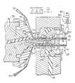
- an apparatus for continuously forming a flexible reinforced hose 10 having a controlled internal size is generally indicated by the reference numeral 12.
- the apparatus 12 includes a conventional braid forming machine 14 which continuously produces a tubular braided reinforcement member 16 having inner and outer surfaces 18, 20, first and second extruders 22, 24 and a die mechanism 25 for forming a liner and cover 26, 28 from elastomeric material, such as rubber, onto the reinforcement member 16, means 30 for continuously monitoring the internal size of the extruded hose 10, control means 32 for controlling the speed of the extruder 22 in response to a change of the internal size of the hose 10 from a predetermined size range, means 34 for marking a portion of the cover 28 to indicate that the internal portion is outside of the predetermined size range, and a take-up mechanism 36 for storing the extruded hose 10 for subsequent curing.
- Each of the extruders 22, 24 includes an extruder screw 38 and a hopper 40 for supplying the elastomeric materials to the die mechanism 25.
- a pair of passages 41, 42 respectively connect the extruder screw 38 of each extruder 22, 24 to the die mechanism 25 and an electric motor 43 drives each of the extruder screws 38.
- the second extruder 24 is adjustably mounted on a base 44 by an adjustment mechanism 45.
- the adjustment mechanism 45 provides both radial and axial adjustment of the second extruder 24 relative to the portion of the die mechanism 25 that is connected to the first extruder 22.
- the adjustment mechanism 45 includes a plurality of adjustment screws 46 positioned around the base of the second extruder 24 and the portion of the base 44 that receives the base of the second extruder 24. It should be recognized that other types of mechanisms could be used to adjust the mounting position of the second extruder 24 without departing from the essence of the invention.
- the braiding machine 14 includes a guide ring 47 and a mandrel 48 on which the reinforcement member 16 is formed.
- a plurality of elongated strands 50 (only a portion of which are shown), such as strands of metallic wire are drawn from a plurality of bobbins 52 carried on rotating spindles on the braiding machine 14 and are directed in a predetermined pattern by the braiding machine across the guide ring 47 onto the mandrel 48.
- Half of the plurality of bobbins 52 are rotating in an opposite direction relative to the other half so that the strands 50 are spirally wrapped on the mandrel 48 in an alternating overlapping interwoven relationship to continuously produce the braided tubular member 16.
- the braided tubular member 16 has a continuous circumferential surface and is made in a continuous linear length.
- the strands 50 are positioned in abutting relationship with one another to form a close knit braid which has a total initial coverage on the mandrel 48 allowing substantially no openings therebetween.
- the monitoring means 30 includes a fluid gauge means 54 for monitoring the internal size of the extruded hose 10, an external source of fluid pressure, such as an air pump 56, and a conduit 58 having an orifice 59 located therein connects the air pump 56 with the fluid gauge means 54.
- the control means 32 includes a pressure transducer 60 connected to the external source 56 of fluid pressure downstream of the orifice 59 by a conduit 62, a signal conditioner 64 connected to the pressure transducer by an electrical line 66, and a motor control 68 connected to the signal conditioner 64 by an electrical line 70 and to the motor 43 of the first extruder by an electrical line 72.
- a source 74 of electrical energy is connected to the motor control 68 for providing a source of electrical energy for the system.
- the marking means 34 includes a marker actuator control 76 connected to the signal conditioner 64 by an electrical line 78, and a marking device 80 mounted on the second extruder 24 and connected to the marker actuator control 76 by an electrical line.82.
- the marking device 80 could be a printing device or a device to scribe a line on the hose or as shown more specifically in Fig. 2, a spray nozzle 84 mounted on the second extruder 24 and having a source of fluid paint 86 and an electrically controlled module 88 for opening and closing the flow of paint to the spray nozzle 84.
- the take-up mechanism 36 includes a take-up reel 90 mounted on a trunnion 92.
- the mandrel 48 includes a tapered outer surface 94 and a bore 96.
- the mandrel 48 has a first end portion 98 terminating in the die mechanism 25 and has a second end portion 100 connected to the first extruder 22.
- the die mechanism 25 includes an internal shaping member 102.
- the internal shaping member 102 extends through the bore 96 of the mandrel 48 and has a first end portion 104 extending beyond the first end portion 98 of the mandrel 48 and has a second end portion 106 which is connected to the first extruder 22.
- a cavity 108 is defined between the bore 96 of the mandrel 48 and the internal shaping member 102. The cavity 108 is connected to the passage 41 through a port 110 located in the second end portion 106 of the internal shaping member 102.
- the fluid gauge means 54 includes a gauging member 112 mounted to the first end portion 104 of the internal shaping member 102.
- a portion 114 of the gauging member 112 extends beyond the first end portion 104 of the internal shaping member 102.
- the portion 114 has a cross-sectional area less than the cross-sectional area of the first end portion 104 which defines a predetermined orifice size between the portion 114 and the optimum internal size of the extruded hose 10.
- a passage 116 located in the internal shaping member freely connects the predetermined orifice to the conduit 58.
- the die mechanism 25 further includes an external shaping member 118 located on the second extruder 24.
- the external shaping member 118 is adjustably positioned on the second extruder 24 by a plurality of screws 119.
- the external shaping member 118 has an inside portion 120 at one end which is radially disposed about the first end portion 104 of the internal shaping member 102.
- An annular space 122 is defined between the first end portion 104 of the internal shaping member 102, the inside portion 120 of the external shaping member 118, and the first end portion 98 of the mandrel 48.
- a chamber 124 connects the annular space 122 with the passage 42 of the second extruder 24.
- the chamber 124 is formed by the one end of the external shaping member 118 and a guide collar 126.
- An internal portion 128 of the guide collar 126 is radially disposed about a portion of the first end portion 104 of the internal shaping member 102.
- the braiding machine 14 braids the strands of wire 50 onto the mandrel 48 to continuously form the reinforcement member 16.
- the mandrel 48 is preferably a tapered mandrel and the braiding of the strands 50 onto the larger end of the tapered surface 94 results in the closely knit braid which allows substantially no openings therebetween.
- the action of the strands 50 being laid adjacent to one another plus the lead of the strands being laid onto the mandrel 48 results in the reinforcement member 16 being progressively pushed towards the smaller end of the tapered surface 94 as a result of the braiding function.
- the liner 26 is extruded onto the inner surface 18 of the reinforcement member 16. This is accomplished by the elastomeric material being extruded into the annular space 122 just beyond the first end portion 98 of the mandrel 48 through the passage 41, port 110 and cavity 108, The first end portion 104 of the internal shaping member 102 forms the internal surface of the liner 26 while the outer portion of the liner 26 is formed by the inner surface 18 of the reinforcement member 16.
- the cover 28 is formed over the reinforcement member 16 by the elastomeric material being extruded into the annular space 122 from the second extruder 24 through the passage 42 and the chamber 124.
- the concentricity of the liner 26 and cover 28 with the braided member 16, is maintained by controlling the relationship of the external shaping member 118 and the guide collar 126 relative to the first end portion 104 of the internal shaping member 102 and the mandrel 48. Since the external shaping member 118 and the guide collar 126 are mounted on the second extruder 24, the adjustment mechanism 45 can simultaneously adjust the external shaping member 118 and guide collar 126 in all directions. Furthermore the plurality of screws 119 can radially adjust the external shaping member 118 relative to the guide collar 126.
- the internal size of the hose 10 is continuously controlled by the fluid gauge means 54 providing a signal to the control means 32 so that the rate of extrusion is changed in response to the internal size of the hose exceeding a predetermined size range.
- the signal to the control means 32 is established by producing a volume of air and monitoring the flow and/or pressure of the air being directed across the predetermined orifice. As shown in this concept a pressure regulating apparatus is being utilized.
- the air pump 56 produces the voJume of air which flows across the orifice 57 through conduit 58 and passage 116 to the predetermined orifice that is established between the portion 114 of the gauging member 112 and inside portion of the liner 26. With the predetermined orifice size, a predetermined amount of air passes thereacross.
- the restriction made by the orifice establishes a pressure signal in the conduit 58.
- This signal which is representative of the internal size of the hose 10 is communicated to the pressure transducer 60 through the conduit 62.
- the pressure transducer 60 translates the pressure signal into an electrical signal and directs the resulting electrical signal to the signal conditioner 64.
- the signal being transmitted from the pressure transducer 60 will stay within a predetermined range and the motor control 68 will continue to operate the motor 43 of the first extruder 22 at a given speed to produce the hose 10.
- the motor control 68 will change the speed of the motor 43 of the first extruder 22 thus adjusting the rate of extrusion of the material which changes the internal size of the hose 10. Consequently, the inside diameter of the hose 10 is maintained which ensures the proper size needed for securing the coupling to the hose.
- the signal conditioner 64 directs an electrical signal to the marker actuator control 76 through the electrical line 78, In response to the electrical signal, the marker device 80 marks the outside portion of the hose 10 that is too far outside of the limits prescribed for the inside diameter. This allows removal of the defective portion.
- the take-up mechanism 36 collects the hose from the die mechanism 25 and maintains it on the take-up reel 90 for subsequent curing of the hose 10.
- the method of manufacturing an elastomeric hose comprises the steps of extruding an elastomeric hose having a predetermined internal size, monitoring the internal size continuously, and controlling the rate of extrusion in response to a change to the internal size from a predetermined size range.
- the method further includes the steps of braiding a reinforcement member on a mandrel, progressively removing the braided member from the mandrel, and wherein the step of extruding the hose includes extruding a liner from a first extruder onto the reinforcement member as it is being removed from the mandrel and extruding a cover from a second extruder onto the reinforcement member at approximately the same axial location as the extrusion of the liner and adjacent the mandrel.
- the method also includes changing the speed of the first extruder in response to the internal size changing from the predetermined size range.
- An additional step includes marking a portion of the hose in response to a change in the internal size of the portion beyond a predetermined size range.
- the method and apparatus provides a continuous hose making process that maintains an accurate internal size without requiring the use of lengthy mandrels for extruding the hose onto.
- the process provides a manufacturing process that produces a reinforced hose on a continuous basis while maintaining the critical internal diameter without requiring large amounts of manufacturing floor space, thus reducing the overall cost of making the hose.
Landscapes
- Engineering & Computer Science (AREA)
- Mechanical Engineering (AREA)
- Extrusion Moulding Of Plastics Or The Like (AREA)
Abstract
Claims (17)
Applications Claiming Priority (2)
| Application Number | Priority Date | Filing Date | Title |
|---|---|---|---|
| US06/508,998 US4490316A (en) | 1983-06-29 | 1983-06-29 | Apparatus and method for controlling internal size of an extruded hose |
| US508998 | 1983-06-29 |
Publications (2)
| Publication Number | Publication Date |
|---|---|
| EP0148176A1 EP0148176A1 (fr) | 1985-07-17 |
| EP0148176B1 true EP0148176B1 (fr) | 1988-06-01 |
Family
ID=24024912
Family Applications (1)
| Application Number | Title | Priority Date | Filing Date |
|---|---|---|---|
| EP83902861A Expired EP0148176B1 (fr) | 1983-06-29 | 1983-08-17 | Dispositif et procede de reglage de la dimension interne d'un tuyau extrude |
Country Status (8)
| Country | Link |
|---|---|
| US (1) | US4490316A (fr) |
| EP (1) | EP0148176B1 (fr) |
| JP (1) | JPH0615192B2 (fr) |
| CA (1) | CA1203960A (fr) |
| DE (1) | DE3376814D1 (fr) |
| IT (1) | IT1176218B (fr) |
| MX (1) | MX160288A (fr) |
| WO (1) | WO1985000138A1 (fr) |
Families Citing this family (17)
| Publication number | Priority date | Publication date | Assignee | Title |
|---|---|---|---|---|
| US4598457A (en) * | 1985-08-26 | 1986-07-08 | Allied Corporation | Method of constructing a brake pedal |
| US4857247A (en) * | 1986-08-18 | 1989-08-15 | Technicon Instruments Corporation | Method for drawing thermoplastic tubing |
| US5246752A (en) * | 1986-08-18 | 1993-09-21 | Technicon Instruments Corporation | Method and apparatus for drawing thermoplastic tubing |
| CA1295104C (fr) * | 1986-09-25 | 1992-02-04 | Helmut Joncker | Methode d'extrusion en continu d'une substance d'elastomere a l'interieur d'unetoile tubulaire tissee en continu dans un faisceau |
| US4738735A (en) * | 1986-11-05 | 1988-04-19 | Mercedes Textiles Limited | Method and apparatus for continuously extruding an elastomeric material on the interior of a continuous tubular woven fabric in a loom |
| US4777860A (en) * | 1987-07-06 | 1988-10-18 | Dana Corporation | Braiding nose |
| US4898702A (en) * | 1988-04-04 | 1990-02-06 | Cordis Corporation | Method and apparatus for removal of a wire mandrel from a catheter |
| JP3231849B2 (ja) * | 1992-08-17 | 2001-11-26 | 株式会社ブリヂストン | 補強ホースの製造方法 |
| US5292472A (en) * | 1992-12-18 | 1994-03-08 | Bridgestone Corporation | Coextrusion apparatus and method with rotating cord guidance |
| US6984351B2 (en) * | 2001-01-23 | 2006-01-10 | Snap-Tite Technologies, Inc. | Apparatus and method for continuously and endlessly vulcanizing rubber hose |
| DE10317554B4 (de) * | 2003-04-15 | 2006-08-17 | Wienerberger Ziegelindustrie Gmbh | Vorrichtung zur Überwachung des Pressdruckes in Anlagen zur Herstellung von stranggezogenen Hintermauerziegeln, Klinkern, Drainagerohren, Spaltplatten, Dachziegeln und anderen keramischen Produkten |
| US7738993B2 (en) * | 2003-10-10 | 2010-06-15 | Boston Scientific Scimed, Inc. | Extrusion of articles |
| JP4743745B2 (ja) * | 2004-01-09 | 2011-08-10 | 株式会社フジキン | 小孔孔径自動計測装置、小孔孔径計測方法及びシャワープレート |
| JP5837870B2 (ja) * | 2012-12-11 | 2015-12-24 | 住友ゴム工業株式会社 | 筒状発泡ゴムの製造方法、および導電性ローラの製造方法 |
| JP2015033767A (ja) * | 2013-08-07 | 2015-02-19 | 住友ゴム工業株式会社 | 導電性発泡ゴムローラの製造方法、導電性発泡ゴムローラ、および画像形成装置 |
| US10232551B2 (en) * | 2016-04-15 | 2019-03-19 | Cc3D Llc | Head and system for continuously manufacturing composite hollow structure |
| DE102020103687B4 (de) * | 2020-02-12 | 2022-05-05 | Battenfeld-Cincinnati Germany Gmbh | Einrichtung zum Anfahren eines Extrusionsprozesses |
Family Cites Families (19)
| Publication number | Priority date | Publication date | Assignee | Title |
|---|---|---|---|---|
| DE1251014B (fr) * | 1967-09-28 | |||
| US29886A (en) * | 1860-09-04 | Corh-sheller | ||
| US2501690A (en) * | 1947-12-09 | 1950-03-28 | Carter Products Corp | Method and apparatus for making multiple layer plastic conduits |
| US2750792A (en) * | 1952-12-09 | 1956-06-19 | Dunlop Tire & Rubber Corp | Apparatus for measuring the bore of tubing |
| US3678271A (en) * | 1969-10-09 | 1972-07-18 | Caterpillar Tractor Co | Marking and detection of subsurface defects in multi-layer hose structures |
| GB1370946A (en) * | 1971-05-14 | 1974-10-16 | Wavin Plastics Ltd | Extrusion of thermoplastics materials |
| JPS5236290B2 (fr) * | 1972-05-02 | 1977-09-14 | ||
| JPS4991664A (fr) * | 1973-01-06 | 1974-09-02 | ||
| US3856595A (en) * | 1973-04-16 | 1974-12-24 | Royle & Sons J | Measurement of dimension of elongated material during its continuous vulcanization |
| US3914356A (en) | 1974-03-28 | 1975-10-21 | Western Electric Co | Methods of and apparatus for controlling the thickness of an annular extrusion |
| DE2557718C3 (de) * | 1974-12-28 | 1979-11-15 | Toyoda Gosei Co. Ltd., Nagoya (Japan) | Vorrichtung zum Herstellen von verstärkten Schläuchen |
| JPS5324157A (en) * | 1976-08-18 | 1978-03-06 | Sanyo Electric Co Ltd | Control circuit of air conditioner |
| JPS5933085B2 (ja) * | 1976-12-09 | 1984-08-13 | クラレプラスチツクス株式会社 | 合成樹脂管の製造方法および製造装置 |
| DE2700003A1 (de) * | 1977-01-03 | 1978-07-06 | Reifenhaeuser Kg | Anlage zur herstellung von strangpressprofilen |
| DE2706085C2 (de) * | 1977-02-12 | 1984-02-02 | Reifenhäuser KG, 5210 Troisdorf | Vorrichtung zum Extrudieren von Rohren aus thermoplastischem Kunststoff |
| US4137025A (en) * | 1977-03-07 | 1979-01-30 | Graves Kenneth E | Apparatus for measuring and controlling the wall thickness of plastic pipes |
| US4161379A (en) * | 1977-07-21 | 1979-07-17 | The Johnson Rubber Company | Apparatus for producing reinforced hose |
| US4367646A (en) * | 1980-11-07 | 1983-01-11 | Allen Sr J Hunter | Apparatus and method for detecting and measuring localized areas of deterioration on the interior of tubes |
| JP5334157B2 (ja) | 2008-07-01 | 2013-11-06 | ハイモ株式会社 | ブロック状共重合体および粘性調節剤ならびに凝集助剤 |
-
1983
- 1983-06-29 US US06/508,998 patent/US4490316A/en not_active Expired - Lifetime
- 1983-08-17 JP JP58502924A patent/JPH0615192B2/ja not_active Expired - Lifetime
- 1983-08-17 DE DE8383902861T patent/DE3376814D1/de not_active Expired
- 1983-08-17 EP EP83902861A patent/EP0148176B1/fr not_active Expired
- 1983-08-17 WO PCT/US1983/001271 patent/WO1985000138A1/fr not_active Ceased
-
1984
- 1984-04-30 CA CA000453118A patent/CA1203960A/fr not_active Expired
- 1984-05-30 IT IT21161/84A patent/IT1176218B/it active
- 1984-06-28 MX MX201811A patent/MX160288A/es unknown
Also Published As
| Publication number | Publication date |
|---|---|
| US4490316A (en) | 1984-12-25 |
| IT1176218B (it) | 1987-08-18 |
| EP0148176A1 (fr) | 1985-07-17 |
| CA1203960A (fr) | 1986-05-06 |
| IT8421161A1 (it) | 1985-11-30 |
| IT8421161A0 (it) | 1984-05-30 |
| JPS60501700A (ja) | 1985-10-11 |
| DE3376814D1 (en) | 1988-07-07 |
| JPH0615192B2 (ja) | 1994-03-02 |
| WO1985000138A1 (fr) | 1985-01-17 |
| MX160288A (es) | 1990-01-25 |
Similar Documents
| Publication | Publication Date | Title |
|---|---|---|
| US4490316A (en) | Apparatus and method for controlling internal size of an extruded hose | |
| US4578024A (en) | Coextrusion apparatus | |
| US4280801A (en) | Crosshead | |
| JPS62167024A (ja) | 2層継目なしプラスチツク・チユ−ブを製造する装置に使用される押出加工金型 | |
| EP0148834B1 (fr) | Procede et dispositif de production de tuyaux renforces tresses | |
| US4995800A (en) | Extrusion die assembly | |
| EP0468261B1 (fr) | Dispositif de coextrusion et procédé pour faire varier le profil intérieur de l'extrudat tubulaire | |
| US4501629A (en) | Method and apparatus for extruding reinforced hose | |
| EP0472864B1 (fr) | Appareil et procédé de coextrusion sous l'utilisation d'une buse élastique pour varier le profil extérieur d'un produit d'extrusion tubulaire | |
| EP0180571A3 (fr) | Filière d'extrusion et procédé d'extrusion avec centrage automatique | |
| JP2005531429A (ja) | 補強材補強されたホース状の構造物を連続的に製造するための装置及び方法 | |
| EP0468268A2 (fr) | Dispositif de coextrusion pour faire varier le profil intérieur et/ou extérieur d'un extrudat tubulaire | |
| IL43327A (en) | Apparatus for producing perforated seamless tubular films | |
| US4946364A (en) | Apparatus for manufacturing reinforced polymeric tubing | |
| JPH06231633A (ja) | ケーブル押出被覆装置 | |
| KR910007194B1 (ko) | 고압용 호스의 제조방법 및 그 장치 | |
| EP1284180A1 (fr) | Anneau d'air avec entraínement motorisé pour le refroidissement d'une feuille soufflée | |
| GB1573574A (en) | Manufacture of tubular sheaths | |
| US4495022A (en) | Extrusion method and apparatus | |
| SU1378779A3 (ru) | Головка дл получени пленочных руковов экструзией с раздувом из термопластичных масс | |
| JPS58510Y2 (ja) | 高分子材料の押出被覆用クロスヘツドダイ | |
| KR100197969B1 (ko) | 송수용 호스의 제조장치 | |
| KR910007192B1 (ko) | 편조보강 호스의 압출 제조장치 및 방법 | |
| JPS5938254Y2 (ja) | 押出成形機 | |
| EP0261877B1 (fr) | Procédé d'extrusion continue d'une matière élastomère sur la surface intérieure d'un tissu tubulaire continu dans un métier à tisser |
Legal Events
| Date | Code | Title | Description |
|---|---|---|---|
| PUAI | Public reference made under article 153(3) epc to a published international application that has entered the european phase |
Free format text: ORIGINAL CODE: 0009012 |
|
| 17P | Request for examination filed |
Effective date: 19850102 |
|
| AK | Designated contracting states |
Designated state(s): DE FR GB |
|
| 17Q | First examination report despatched |
Effective date: 19860313 |
|
| RAP1 | Party data changed (applicant data changed or rights of an application transferred) |
Owner name: CATERPILLAR INC. |
|
| GRAA | (expected) grant |
Free format text: ORIGINAL CODE: 0009210 |
|
| AK | Designated contracting states |
Kind code of ref document: B1 Designated state(s): DE FR GB |
|
| REF | Corresponds to: |
Ref document number: 3376814 Country of ref document: DE Date of ref document: 19880707 |
|
| ET | Fr: translation filed | ||
| PLBE | No opposition filed within time limit |
Free format text: ORIGINAL CODE: 0009261 |
|
| STAA | Information on the status of an ep patent application or granted ep patent |
Free format text: STATUS: NO OPPOSITION FILED WITHIN TIME LIMIT |
|
| 26N | No opposition filed | ||
| PGFP | Annual fee paid to national office [announced via postgrant information from national office to epo] |
Ref country code: GB Payment date: 19910715 Year of fee payment: 9 |
|
| PG25 | Lapsed in a contracting state [announced via postgrant information from national office to epo] |
Ref country code: GB Effective date: 19920817 |
|
| GBPC | Gb: european patent ceased through non-payment of renewal fee |
Effective date: 19920817 |
|
| PGFP | Annual fee paid to national office [announced via postgrant information from national office to epo] |
Ref country code: FR Payment date: 19960703 Year of fee payment: 14 |
|
| PG25 | Lapsed in a contracting state [announced via postgrant information from national office to epo] |
Ref country code: FR Free format text: LAPSE BECAUSE OF NON-PAYMENT OF DUE FEES Effective date: 19980430 |
|
| REG | Reference to a national code |
Ref country code: FR Ref legal event code: ST |
|
| PGFP | Annual fee paid to national office [announced via postgrant information from national office to epo] |
Ref country code: DE Payment date: 20020830 Year of fee payment: 20 |