EP0148266B1 - Systemes de communications optiques a multiplexage par division de longueurs d'ondes - Google Patents
Systemes de communications optiques a multiplexage par division de longueurs d'ondes Download PDFInfo
- Publication number
- EP0148266B1 EP0148266B1 EP84903500A EP84903500A EP0148266B1 EP 0148266 B1 EP0148266 B1 EP 0148266B1 EP 84903500 A EP84903500 A EP 84903500A EP 84903500 A EP84903500 A EP 84903500A EP 0148266 B1 EP0148266 B1 EP 0148266B1
- Authority
- EP
- European Patent Office
- Prior art keywords
- optical
- accordance
- optical device
- resonator
- waveguide
- Prior art date
- Legal status (The legal status is an assumption and is not a legal conclusion. Google has not performed a legal analysis and makes no representation as to the accuracy of the status listed.)
- Expired - Lifetime
Links
- 230000003287 optical effect Effects 0.000 title claims abstract description 174
- 238000004891 communication Methods 0.000 title description 13
- 230000005540 biological transmission Effects 0.000 claims description 26
- 239000013307 optical fiber Substances 0.000 claims description 21
- 239000004065 semiconductor Substances 0.000 claims description 16
- 239000002019 doping agent Substances 0.000 claims description 5
- 229910052779 Neodymium Inorganic materials 0.000 claims description 3
- 230000000694 effects Effects 0.000 claims description 3
- QEFYFXOXNSNQGX-UHFFFAOYSA-N neodymium atom Chemical compound [Nd] QEFYFXOXNSNQGX-UHFFFAOYSA-N 0.000 claims description 3
- 238000010168 coupling process Methods 0.000 description 49
- 230000008878 coupling Effects 0.000 description 48
- 238000005859 coupling reaction Methods 0.000 description 48
- 239000000835 fiber Substances 0.000 description 26
- 230000003595 spectral effect Effects 0.000 description 16
- 230000000977 initiatory effect Effects 0.000 description 14
- 238000013461 design Methods 0.000 description 6
- 239000011521 glass Substances 0.000 description 6
- 238000004519 manufacturing process Methods 0.000 description 6
- 238000000034 method Methods 0.000 description 6
- 238000005253 cladding Methods 0.000 description 5
- 230000001902 propagating effect Effects 0.000 description 5
- 239000000758 substrate Substances 0.000 description 4
- 238000013459 approach Methods 0.000 description 3
- 238000005086 pumping Methods 0.000 description 3
- VYPSYNLAJGMNEJ-UHFFFAOYSA-N Silicium dioxide Chemical compound O=[Si]=O VYPSYNLAJGMNEJ-UHFFFAOYSA-N 0.000 description 2
- 230000008859 change Effects 0.000 description 2
- 238000012937 correction Methods 0.000 description 2
- 230000003247 decreasing effect Effects 0.000 description 2
- 238000012423 maintenance Methods 0.000 description 2
- 238000005457 optimization Methods 0.000 description 2
- 230000005855 radiation Effects 0.000 description 2
- 241000282461 Canis lupus Species 0.000 description 1
- 229910001218 Gallium arsenide Inorganic materials 0.000 description 1
- 238000010521 absorption reaction Methods 0.000 description 1
- 230000032683 aging Effects 0.000 description 1
- 230000003466 anti-cipated effect Effects 0.000 description 1
- 230000003139 buffering effect Effects 0.000 description 1
- 239000004568 cement Substances 0.000 description 1
- 230000001419 dependent effect Effects 0.000 description 1
- 230000001066 destructive effect Effects 0.000 description 1
- 238000001514 detection method Methods 0.000 description 1
- 239000006185 dispersion Substances 0.000 description 1
- 230000005684 electric field Effects 0.000 description 1
- 239000000284 extract Substances 0.000 description 1
- 238000001459 lithography Methods 0.000 description 1
- 230000003278 mimic effect Effects 0.000 description 1
- 239000000203 mixture Substances 0.000 description 1
- 230000010355 oscillation Effects 0.000 description 1
- 230000003071 parasitic effect Effects 0.000 description 1
- 230000000737 periodic effect Effects 0.000 description 1
- 238000011084 recovery Methods 0.000 description 1
- 230000001172 regenerating effect Effects 0.000 description 1
- 230000004044 response Effects 0.000 description 1
- 238000000926 separation method Methods 0.000 description 1
- 238000004904 shortening Methods 0.000 description 1
- 230000008054 signal transmission Effects 0.000 description 1
- 239000000377 silicon dioxide Substances 0.000 description 1
- 238000001228 spectrum Methods 0.000 description 1
- 230000006641 stabilisation Effects 0.000 description 1
- 238000011105 stabilization Methods 0.000 description 1
Images


Classifications
-
- H—ELECTRICITY
- H04—ELECTRIC COMMUNICATION TECHNIQUE
- H04B—TRANSMISSION
- H04B10/00—Transmission systems employing electromagnetic waves other than radio-waves, e.g. infrared, visible or ultraviolet light, or employing corpuscular radiation, e.g. quantum communication
- H04B10/60—Receivers
- H04B10/66—Non-coherent receivers, e.g. using direct detection
- H04B10/67—Optical arrangements in the receiver
- H04B10/671—Optical arrangements in the receiver for controlling the input optical signal
- H04B10/675—Optical arrangements in the receiver for controlling the input optical signal for controlling the optical bandwidth of the input signal, e.g. spectral filtering
-
- H—ELECTRICITY
- H04—ELECTRIC COMMUNICATION TECHNIQUE
- H04J—MULTIPLEX COMMUNICATION
- H04J14/00—Optical multiplex systems
- H04J14/02—Wavelength-division multiplex systems
- H04J14/0227—Operation, administration, maintenance or provisioning [OAMP] of WDM networks, e.g. media access, routing or wavelength allocation
- H04J14/0228—Wavelength allocation for communications one-to-all, e.g. broadcasting wavelengths
-
- H—ELECTRICITY
- H04—ELECTRIC COMMUNICATION TECHNIQUE
- H04J—MULTIPLEX COMMUNICATION
- H04J14/00—Optical multiplex systems
- H04J14/02—Wavelength-division multiplex systems
- H04J14/0227—Operation, administration, maintenance or provisioning [OAMP] of WDM networks, e.g. media access, routing or wavelength allocation
- H04J14/0241—Wavelength allocation for communications one-to-one, e.g. unicasting wavelengths
-
- H—ELECTRICITY
- H04—ELECTRIC COMMUNICATION TECHNIQUE
- H04J—MULTIPLEX COMMUNICATION
- H04J14/00—Optical multiplex systems
- H04J14/02—Wavelength-division multiplex systems
- H04J14/0278—WDM optical network architectures
- H04J14/0283—WDM ring architectures
Definitions
- This invention relates to an optical device comprising, a waveguide resonator a photodetector and the resonator is adapted to be evanescently coupled to an optical waveguide (F) and optically coupled to the photodetector.
- Optical communications systems as presently contemplated have a light source and a photodetector which are optically coupled to each other by a glass transmission line.
- the glass transmission line presently has a silica based composition and is commonly referred to as an optical fiber.
- a light source commonly used in such optical communications systems is a semiconductor laser diode.
- Such optical communications systems have been developed to a high degree of sophistication and are now capable of rapidly transmitting large amounts of information over long distances.
- the diode In most present day systems, only one such diode is used to transmit information on any individual fiber, and the diode should ideally operate with essentially a stable single frequency spectral output. Information is transmitted as the laser emits or does not emit light pulses thus forming a bit stream, and the photodetector receives or does not receive light pulses within predetermined time intervals.
- Transmission systems usually called trunks carry calls between central offices.
- Loop plant connects the central office to the customer station or equipment.
- Local area networks carry calls between locations that are located on customer premises, e.g., between a computer and work station, and are useful for factory or office automation.
- the photodetector component includes means to individually detect the separated frequencies or wavelengths, i.e., the photodetector has demultiplexing means.
- Radio circuits are typically much smaller than the radio wavelengths and microwave circuits have dimensions comparable to microwave wavelengths.
- Optical multiplexers smaller than an optical wavelength are not likely given the resolution of present lithography used in device fabrication and would also be difficult to couple optical energy into and out of.
- Optical wavelength division multiplexing devices are thus larger than optical wavelengths and fundamentally different from radio and microwave systems.
- wavelength division multiplexing in optical communications systems is reviewed in an article by W. J. Tomlinson in Applied Optics , 16 , pp. 2180-2194, August, 1977.
- the systems described are typical and all have a multi-transmitter module at one end and a multi-receiver module at the other end.
- the systems are presently contemplated only for trunks. They are not easily adaptable for either loop plant operation or a local area network because the optical fiber cannot be easily tapped at arbitrary places without first detecting all the signals and then regenerating them.
- Individual components discussed by Tomlinson are, however, illustrative.
- Multiplexing and demultiplexing means typically comprise either gratings, prisms, or filters.
- evanescent couplers uses at least two optical waveguides in such close proximity that the propagating mode of the second waveguide is within the exponentially decaying evanescent portion of the propagating mode of the first waveguide. This is called overlap.
- the overlap couples optical energy from the first waveguide into the second waveguide if the propagation constants, k , in the two guides are equal. If the values of k are equal at only a single frequency, then only energy at that frequency is coupled while energy at other frequencies remains in the first guide. H.
- the resonator disclosed is an integrated device, that is, the waveguides and resonant ring are fabricated on a single substrate, it is not well adapted for use with optical fiber communications systems.
- Another device of general interest is the integrated linear Fabry-Perot resonator described by Smith et al in Applied Physics Letters , 34 , pp. 62-65, January 1, 1979. The device described required no external electrical inputs and used only optical outputs. The use contemplated was in bistable optical devices.
- the problems are that the typical prior art wavelength division multiplexing systems use a very wide optical bandwidth to accommodate the frequency variations of semiconductor lasers and the total number of channels is very limited.
- Some narrower bandwidth system components were demonstrated, for example, frequency selective evanescent couplers, but have not been used in systems because of the absence of a precise narrow bandwidth source and the difficulty in matching transmitter and receiver bandwidths center frequencies. Additionally, the systems are not easily adapted for loop plant or local area network operation.
- a device as set out in the preamble of claim 1 is disclosed in Wo-A-83/02168.
- an optical device as set out in claim 1.
- the optical communications system comprises an optical fiber and a device comprising a photodetector; a waveguide resonator that is evanescently coupled to an optical fiber and optically coupled to said photodetector; an intracavity element optically coupled to the waveguide resonator; and a control circuit element which tunes either the intracavity element or the waveguide resonator to specific frequencies.
- the system comprises a plurality of devices which may be optically coupled to the system's fibers at any place. The devices are independently tunable thereby permitting a signal having a desired frequency to be either received or transmitted.
- the devices perform frequency selective coupling from the fiber to the transceiver and thereby couple to the desired optical channel frequency, yet have negligible attenuation of the undesired channels remaining in the fiber. This permits a signal having a desired wavelength to be received with negligible attenuation of unwanted signals at other wavelengths.
- An optical gain element in the resonator or coupled to the resonator yields a device which can transmit thereby permitting transmission of a signal in the optical fiber at a desired wavelength.
- the waveguide resonator comprises an optical fiber loop which is coupled to the optical fiber.
- the intracavity element may comprise an optical fiber loop coupled to the main Fabry-Perot resonator or it may comprise a waveguide Mach-Zehnder interferometer or a three coupler waveguide Mach-Zehnder interferometer.
- the control circuit element further comprises link initiation and maintenance means.
- other resonators such as linear or pillbox resonators, may be used.
- Other intracavity elements such as linear resonators, may also be used.
- Grating or acousto-optic assisted wavelength selective weak coupling from resonator to system fiber may also be used.
- FIG. 1 is a schematic representation of one optical communications system according to this invention
- FIG. 2 is a schematic representation of an optical receiver module of a system according to this invention.
- FIGS. 3-5 are schematic representations of several embodiments of an intracavity element design useful with an optical receiver or optical transmitter module of a system according to this invention
- FIGS. 6-7 are schematic representations of evanescent coupling intracavity elements useful in this invention.
- FIG. 8 is a schematic representation of an optical transmitter module of a system according to this invention.
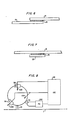
- FIGS. 9-11 are schematic representations of several embodiments of an intracavity element design useful with an optical transmitter or optical receiver module of a system according to this invention.
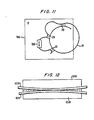
- FIG. 12 is a schematic representation of an evanescent coupler.
- the system comprises a plurality of transceivers indicated as T1, T2, etc., TN-l, TN, which are optically coupled to an optical transmission line, F.
- the optical transmission line commonly referred to as an optical fiber, has characteristics that are well known to those skilled in the art and need not be described further in detail.
- the optical fiber comprises a high refractive index core surrounded by a low index cladding. It should preferably be a single mode optical fiber.
- the transceivers comprise both transmitter and receiver modules.
- the transceivers are independently tunable to common frequencies and thus may be coupled to each other when, for example, the receiver module of a first transceiver is tuned to the frequency of the transmitter module of a second transceiver. For a complete two way link, the receiver module of the second transceiver is tuned to the frequency of the transmitter module of the first transceiver.
- the transmitter and receiver modules are optically coupled to the system fiber by evanescent field coupling as described in detail later.
- the number of transceivers is not critical and may be as large as, or even larger than, the number of optical channels.
- Each transceiver may also include its own independent local control system which performs functions such as tuning, internal optical alignment, link initiation and maintenance, plus systems functions.
- Each transceiver can be independently coupled to the optical transmission line anywhere along the length of the line and this system may thus be used for loop plant and local area network applications as well as trunks applications.
- the tunability permits any transceiver to communicate with any other transceiver thus performing a switching function. This is useful in, for example, factory automation local area networks where the robots or computers would be able to communicate directly with any other robot or computer or in office automation applications.
- FIG. 2 is a schematic representation of the receiver module of a transceiver as depicted in FIG. 1.
- the receiver comprises a main resonator guide 10 which further comprises an intracavity dispersive loss element (IE) 50.
- IE intracavity dispersive loss element
- PD photodetector
- CCE control circuit element
- REC receiver
- the control circuit element is connected to the photodetector 500, main resonator guide 10, the dispersive loss element 50, and the receiver 300.
- the main resonator guide is optically coupled to both the optical fiber and photodetector by evanescent coupling means 20.
- the control circuit provides means, as indicated by arrows 1000 and 1010, to tune the main resonator guide and the intracavity element to desired frequencies.
- the receiver takes the electrical signal from the photodetector and recovers the information from the signal.
- the photodetector and resonator may be evanescently coupled although other means of optical coupling may also be used.
- main resonator guide is depicted as being a loop, it is to be understood that other resonator configurations are contemplated.
- linear and pillbox resonators are also contemplated.
- a pillbox resonator is a special case of a loop resonator in which the ring diameter shrinks until the center hole vanishes.
- the tunability of the resonator is desirable because it enables the wavelength of the receiver resonator of a first transceiver to match the wavelength of the transmitter of a second transceiver.
- the tunability may be accomplished by, for example, varying the effective optical length of the resonator by means such as the electro-optic effect or mechanical strain. This moves the Fabry-Perot resonances. It is often desirable that most of the power from the channel selected be coupled to the detector. For this to be accomplished, the system guide to resonator coupling should equal the detector to main resonator guide coupling.
- the intracavity dispersive loss element 50 is frequency dependent and selects a single Fabry-Perot resonant peak of the main resonator by lowering the Q of the cavity at other resonances. Two conditions must be satisfied at the main resonator cavity resonance. First, the intracavity element loss must be a minimum and, second, there must be an integral number of optical wavelengths per main resonator cavity roundtrip.
- the resonator is typically very weakly coupled to the system waveguide, that is, the optical fiber, to avoid any appreciable coupling to undesired channels.
- the high cavity Q typically 102, resonantly enhances the coupling of the desired signal and even a small loss eliminates unwanted resonances.
- the intracavity element transmission peak can be relatively broad because it is effectively sharpened by the intracavity resonance. However, the peak loss must be low.
- the control circuit also aligns the transmission peak of the intracavity loss element with the cavity resonance selected. Tuning means 1000 varies the appropriate optical path length. The No must be tracked simultaneously to tune the receiver frequency to the desired transmitter. As will be explained later, after this has been accomplished, the receiver must track the transmitter selected.
- the receiver module comprises a control circuit element which uses the output of the photodetector 500 to track the tuning means 1010 to align one of the main resonator Fabry-Perot resonances with a desired optical signal. It may further track tuning means 1000 to align the intracavity element 50 to select the resonance aligned with the desired signal.
- the operation of the main resonator guide may be better understood from the following discussion.
- the operation of the resonator may be easily understood by considering the analogy with a conventional discrete optics Fabry-Perot interferometer which has two 99 percent reflecting and 1 percent transmitting mirrors which are parallel to each other and separated by a distance, d , to form a resonant cavity. If a beam of monochromatic light is now incident upon one of the mirrors, initially 1 percent of the beam power, that is, 10 percent of the electric field, will be transmitted into the cavity and 99 percent of the power will be reflected. The light inside the cavity travels to the other or output mirror and is reflected back toward the input mirror where it is again reflected.
- the reflected wave will add in phase with the input light and interfere constructively.
- the cavity field is now approximately 0.2 times the incident field and the cavity power is approximately 0.04 times the incident power.
- the field is approximately 0.3 times the incident field and the cavity power is approximately 0.09 times the incident power.
- the resonant cavity power is approximately 99 times the incident power and the 1 percent leakage out the input mirror is exactly 180 degrees out of phase with the 99 percent reflection for the incident beam. The two cancel by destructive interference and leave essentially no reflected power.
- the 1 percent leakage of the 99 times incident power resonant wave at the output mirror gives a transmitted beam of essentially the same power as the incident beam.
- the Fabry-Perot transmission peak is exceedingly narrow in wavelength because the cavity light must remain in phase with the input light over many cavity roundtrips to build up a large cavity resonant power.
- the relatively long build-up time of the cavity power also reflects the narrow bandwidth achievable. For example, a pulse whose duration is short compared to the resonator round trip transit time will be rejected as its frequency spectrum is too broad.
- the loop Fabry-Perot main resonator guide is analogous.
- the weak evanescent couplers correspond to the input and output mirrors and the resonant condition is the requirement that there be an exactly integral number of wavelengths around the loop. If there is monochromatic light being transmitted through the system fiber, it will be incident on the evanescent coupling means to the main resonator guide. Initially most of the energy will pass by and only a fraction of the energy is coupled into the resonator.
- the receiver bandwidths are sufficiently narrow as compared to the optical carrier frequency that a control system should generally be used to provide frequency stabilization. It is also apparent that a simple loop resonator has multiple, regularly spaced resonances as do all Fabry-Perot resonators. If the desired resonance has n wavelengths per cavity roundtrip, the next higher frequency resonance has n + 1 and the next higher n + 2, etc. The spacing between the peaks is called a "free spectral range" (FSR). The intracavity element is used to select the single Fabry-Perot peak by lowering the loop Q at the unwanted resonances.
- FSR free spectral range
- Evanescent couplers are used for both the input and output coupling to the main resonator guide as well as in some applications which will be discussed later.
- An evanescent coupler comprises two waveguides in such close proximity to each other over part of their length that the propagating modes in the two waveguides overlap. This overlap couples energy between the two guides.
- the two waveguide cores typically do not touch each other because the propagating mode is not confined to the core. Outside the core, the mode comprises an evanescent wave which typically decays exponentially in distance from the core.
- the principal coupling overlap is between the evanescent tails of the propagating modes in the two guides.
- k( ⁇ ) should be approximately equal in the two waveguides. ⁇ is 2 ⁇ f, where f is the frequency.
- An exemplary evanescent coupler is depicted in sectional view in FIG. 12. It comprises two blocks 1230 and 1240 fabricated from, for example, glass or plastic, having grooves cut within them into which two optical fibers 1210 and 1220, respectively, are inserted. Each fiber follows a curved path, as shown, and is embedded at the edges of the block but rises to the surface near the center of the block. The fibers are curved to diverge from the coupling region to facilitate their handling and coupler fabrication.
- the blocks are polished so that a portion of the fiber cladding is removed near the center of the block where the fiber rises to the surface.
- the blocks are then placed together to form a complete coupler.
- An index matching optical cement may be used to hold the blocks together and to thereby improve the coupling and reduce scattering loss.
- Evanescent couplers between two integrated optic waveguides may be made simply by fabricating the two waveguides close together on a common substrate.
- FIGS. 3-5 are schematic representations of several embodiments of an intracavity element (IE) design according to this invention.
- the intracavity elements fall into one of at least three preferred general categories.
- the first category comprises the Mach-Zehnder IE such as those depicted in FIGS. 3 and 4.
- FIGS. 3 and 4 depict, respectively, two and three coupler Mach-Zehnder IEs.
- the resonant wave is split between the two guides 10 and 70 at the first coupler and the two parts travel different paths i.e., different optical path lengths to the second coupler. If they arrive in phase at the second coupler, all of the power is returned to the main resonator guide. If they do not arrive in phase, some remains in the second guide and is lost.
- a disadvantage of the two coupler IE is the requirement that the two couplers 20 be of exactly the same coupling strength. This disadvantage is removed with a modified Mach-Zehnder three coupler embodiment depicted in FIG. 4 in which the second guide 70 comprises loops 71 and 72. This avoids matching the coupling strength and furthermore has extra selectivity.
- the two loops of the three coupler embodiment are each characterized by their own free spectral range and the receiver module control circuit element therefore has an extra alignment requirement. Tuning is achieved in both by varying the optical path length of the Mach-Zehnder loops by, for example, mechanical strain or electro-optic means.
- the two coupler version of FIG. 3 is the waveguide analog of the discrete optic Mach-Zehnder interferometer. See, for example, Born and Wolf, Principles of Optics , 4th edition, pp. 312-315, 1970. The IE transmission peaks occur when the difference in the optical path lengths is an integral number of wavelengths.
- the three coupler embodiment is presently preferred because of simplicity of fabrication and selectivity.
- guide 70 is coupled to the main resonator 10 by evanescent coupling means 20. It should be noted that complete decoupling between guides 10 and 70 is not required and may be difficult to obtain in integrated optics embodiments.
- the second IE category comprises a resonator IE such as that depicted in FIG. 5.
- the loop resonator 70 is coupled to the main resonator by evanescent coupling means 20.
- the transmission peaks are at frequencies where there are an integral number of wavelengths per round trip.
- a loop resonator is depicted, it is to be understood that other resonators may be used. For example, pillbox or linear resonators may also be used.
- Evanescent coupler IEs are depicted in FIGS. 6 and 7. These are also potentially of interest, particularly in integrated optics embodiments.
- FIG. 6 depicts a segment of an optical resonator having a main guide 10, the ends of which are coupled to each other by an IE comprising evanescent coupling means 20.
- FIG. 7 depicts an IE in which the main waveguide 10 is coupled to a second waveguide 121 by evanescent coupling means 20. Versions with identical propagation constants in the two guides and multiple crossover lengths in the coupling region correspond to the no decoupling limit in the Mach-Zehnder IE. The apparent path length difference seen by the modes of the two coupled waveguides can be tuned electro-optically by separate electrodes on the two guides.
- the resonator IEs are not presently as attractive as are the Mach-Zehnder IEs.
- the resonator IEs are of special interest for integrated optics embodiments because their potential extra loss penalty is more easily controlled. They also have sharper transmission peaks. Although this extra selectivity is often not needed in receivers, it may be useful in transmitters if oscillation in unwanted or parasitic modes becomes a problem.
- the drawbacks to resonator IEs include higher potential losses at the transmission peaks which are a lesser problem in integrated optics embodiments.
- the receiver tuning will now be described for a main resonator for an exemplary embodiment with a two coupler Mach-Zehnder IE. Assume the receiver will be tuned to a still higher frequency.
- the receiver bandwidth is defined by the main cavity resonance selected by the IE and this resonance is tuned upward in frequency by shortening the optical length of the main resonator guide.
- the IE peak frequency is tracked to follow by decreasing the path length difference by the same means.
- the control system can step the main resonator back by one free spectral range thus leaving the IE unchanged.
- the next higher Fabry-Perot resonance is now aligned with the IE peak and the receiver pass band is unchanged by the stepback because the next higher Fabry-Perot peak is directly substituted for the original peak.
- the control system executes yet another mode stepback.
- the control circuit element executes an IE stepback of one free spectral range. This tuning technique ensures that neither the main resonator nor the IE needs to tune significantly more than one free spectral range. To tune either through a free spectral range requires an optical path length change of only one wavelength.
- an exemplary initial alignment search executed by the control circuit element assumes that at least one transmitter is operating and then executes a two-dimensional search over the main resonator guide free spectral range and the IE free spectral range. This is effectively a search over the entire system bandwidth.
- the step size in each direction is typically of the order of the free spectral range divided by the finesse so that any transmitter will be detected. Finesse is the ratio of the free spectral range to the full width at half maximum of the resonance.
- the receiver tracks the transmitter while data is being passed. This is performed by a two-dimensional optimization routine which continually varies both the MRG and the IE tuning so that they are aligned with the transmitter frequency. When either reaches the center of the tuning range within appropriate limits, a mode stepback is executed during the appropriate control interval. Note that a mode stepback will interrupt the data stream and introduce errors unless the data as transmitted over the link contains periodic "control intervals" during which mode stepbacks, and other control functions, are executed.
- Dead spaces in the information stream which are useful for control intervals are expediently created by transmitting information at a rate faster than received by the transmitter as well as data buffering at both transmitter and receiver.
- the receiver rejection of off-resonance optical channels is typically approximately the product of the main resonator guide to system fiber coupling times the main resonator guide to detector coupling. If both are approximately 1 percent couplers, the cross talk rejection is about 10 ⁇ 4. This is not adequate for applications having extremely large numbers of channels.
- the first resonator is coupled to the system fiber and the second resonator is evanescently coupled to the first resonator.
- the optical signal for the photodetector and signal recovery is taken from the second resonator.
- the first resonator must include an IE and the second resonator typically includes an IE although it need not.
- the first resonator further includes a monitor detector which extracts enough signal so that a single resonator receiver control system in the control circuit element can be used to run it.
- the second resonator is tracked to be aligned with the channel transmitted by the first resonator. This technique doubles the cross talk rejection in dB.
- a third possible solution uses a resonator IE and couples the detector to the IE resonator rather than the main resonator.
- a fourth solution uses wavelength selective evanescent coupling from resonator to fiber.
- FIG. 8 An embodiment of a transmitter according to this invention is depicted schematically in FIG. 8.
- the transmitter further comprises an optical gain element 700 in addition to the elements depicted for the optical receiver module.
- the addition of the optical gain element turns the main resonator into a laser with the particular lasing resonance being selected by the IE.
- Tuning means 1030 varies the optical path length within optical gain element 700.
- the transmitter intracavity loss element is generally the same as those described for the receiver.
- the transmitter resonant cavity must be weakly coupled to the system waveguide to avoid coupling appreciable power from other channels. Thus, the transmitter resonator must have a high Q.
- the first comprises a waveguide section containing an optically pumped lasing dopant such as neodymium, i.e., the waveguide and dopant comprise the optical gain element. Either the waveguide core or cladding or both may be doped.
- the system presently preferred is neodymium in glass, and the inhomogeneous broadening due to the glass spreads the multiple Nd lines to form a continuum.
- An exemplary Nd-doped optical fiber transmitter according to this invention is shown schematically in FIG. 9. It comprises the main resonator guide 10 coupled to the system fiber F by evanescent coupling means 20 and the three coupler Mach-Zehnder IE 700.
- Pump source 750 can be a conventional light source such as a GaAs laser or light emitting diode coupled to either the core or cladding.
- Tuning means 1040 controls the optical pumping level.
- Tuning means 1050 and 1060 tune the sections of the Mach-Zehnder IE.
- the Nd-doped glass resonator is an intrinsically high Q laser because Nd is a four-level lasing system. Therefore, the nonexcited atoms do not absorb at the lasing frequency. This is desirable because it means that the unpumped resonator has a high Q and can be used as an optical receiver either for the transmitter frequency control routine or as a data receiver. The latter lends itself readily to transceiver embodiments in which one resonator is time shared between transmitting and receiving.
- An optical gain element comprises an organic dye in, for example, plastic.
- the second optical pumping technique is prism or evanescent coupling of the pump light to the cladding.
- the second class of transmitter optical gain elements comprise semiconductor optical gain elements. Typically, this would be a semiconductor laser chip with antireflection coated facets so that the lasing is due to external feedback. However, because present semiconductor gain chips have both high gain and high absorption, they typically require impedance matching to the high Q main resonator.
- the gain element is advantageously optically coupled to the fiber by lenses, as is well known to those skilled in the art.
- a tunable semiconductor laser can be substituted for the optical gain element if the laser is tuned to the main resonator resonance.
- the main resonator then provides extra feedback which narrows the semiconductor laser's linewidth.
- the modified three coupler Mach-Zehnder IE is illustrated in FIG. 11. This embodiment is analogous to the modified three coupler Mach-Zehnder IE depicted in FIG. 9 but one of the loops is interrupted to include an optical gain element (OG) 760.
- the fraction of the resonant power that is coupled to the gain element is equal to the power coupling ratio of the last IE coupler and that coupler is typically weaker than the other two IE couplers.
- Any Mach-Zehnder IE can be used as an optical impedance matching coupler by inserting the optical gain element in one of the loops.
- a still further class of semiconductor optical gain elements comprises separate lasing and coupling resonators.
- the coupling resonator is weakly evanescently coupled to the system fiber and the lasing resonator is weakly coupled to the coupling resonator.
- the two-resonator transmitter approach has several advantages.
- First, the lasing and coupling functions may be optimized separately.
- a low Q lasing resonator driving a high Q coupling resonator is a form of optical impedance matching.
- the lasing resonator optical gain can be turned off and the high Q coupling resonator can be used as a receiver.
- the two resonator semiconductor gain element designs turning off the semiconductor optical gain element spoils the Q of the lasing resonator thus effectively decoupling it from the coupling resonator which can then be used as a receiver.
- the two resonator transmitter designs are preferred for some applications including those transceiver designs in which one resonator is time shared between transmitting and receiving.
- Transmitter tuning is similar to the receiver tuning already described.
- the lasing frequency is defined by the main cavity resonance selected by the IE.
- the frequency is tracked by tuning the main cavity resonance and tracking the IE peak to follow.
- both are tuned by varying the appropriate optical path length.
- the control system initiates and also optimizes and maintains the transmitter optical alignment. Initiation is by, for example, IE scanning and detection of the onset of lasing. This means tracking the IE to track the lasing resonance of the main resonator. This is expediently performed by using the control circuit element to vary the IE tuning to maximize the ratio of the laser output to pump power.
- the transmitter control also provides means to modulate the transmitted signal to permit information to be transmitted.
- the modulation may be either frequency modulation or amplitude modulation. Techniques for these types of modulations are well known to those skilled in the art using the elements described, and need not be described in detail.
- the different transmitters should be tracked to avoid optical channel overlap and to maintain the required frequency separation. It is a systems level function, and will be described below with the systems level operation.
- One exemplary embodiment of my invention is a transmission system comprising a plurality of transmitters forming a first unit near one end of the transmission fiber and a plurality of receivers forming a second unit near the other end of the transmission fiber.
- the first unit further comprises a control circuit element comprising a transmitter central control unit and a coupled transmitter monitor receiver.
- the second unit further comprises a control circuit element comprising a receiver central control unit.
- the transmitter central control unit scans the frequency band with the monitor receiver and issues the required corrective tuning commands to each transmitter's local control routine.
- the transmitters have random frequencies and the control routine sorts them by having each transmit its own "call sign.”
- the call sign transmission also allows the receiver central control unit to scan each receiver to lock on its designated transmitter.
- the receiver central control Once lock is achieved, it is maintained by the receiver's local control routine. Once all receivers are aligned, the receiver central control so notifies the transmitter central control via a backlink, e.g., a similar transmission system in the opposite direction, and data transmission begins.
- a backlink e.g., a similar transmission system in the opposite direction
- a preferred embodiment comprises a plurality of independent transceivers, each of which can be coupled to the system fiber anywhere along its length, and each of which can tune to any other.
- the transceiver's overall control system comprises frequency control means to avoid channel overlap plus link initiation means.
- the first transceiver control system function is tracking the individual transmitter's frequency to avoid channel overlap.
- the nearest neighbor control technique in which each transceiver responds only to the position in frequency of the two spectrally neighboring optical channels, is preferred.
- Such a control system first determines the relative spectral locations of the two neighboring channels, typically by turning off the transmitter optical gain element, and using the transmitter resonator as a receiver to execute a frequency scan to find the neighboring channels. The frequency scan is executed during a control interval to avoid interruption to the data transmission. The transmitter then resumes transmitting at the original frequency.
- a channel spacing correction function (CSCF) which may be implemented by, for example, the CCE, is then used to calculate the corrective tuning increment and the transmitter then tunes to the new frequency slowly enough to permit the receiver to which the data is being sent to follow.
- the tuning speed must be slower than the response rate of the receiver alignment/tracking routine. The cycle then repeats, beginning with a new scan during the next control interval.
- the nearest neighbor CSCF used in the individual transmitters must be chosen so that the string of transmitters in frequency space is stable.
- the presently preferred CSCFs have mechanical analogs.
- a simple harmonic CSCF mimics a plurality of masses coupled by springs. Any disturbance propagates down the plurality of masses, i.e., channel string, and is absorbed at the end mass.
- the diffusive CSCFs mimic a plurality of massloss points coupled by springs and dashpots. In a diffusive CSCF, the corrective increment is proportional to the error.
- a "hard shell core potential" can be added to either to avoid a tuning increment causing a channel overlap.
- Double-sided CSCFs track the transmitter frequency to the average of the nearest neighbor frequencies on both sides except for the transmitters at the ends of the string. These are tracked to the desired channel frequency spacing from their nearest neighbor.
- Single-sided CSCFs track the transmitter frequency to the desired channel spacing above the low frequency neighbor. The single-sided CSCFs are preferred because the channel spacing information is applied at each transceiver.
- CSCF typically may also comprise a small drift term adding a small step towards the peak of the gain curve to each frequency correction.
- the effect of this term in all the transceivers is to center the channel string under the optical gain curve peak.
- a second transceiver control system function is called "link initiation.” Ideally, this function should allow any transceiver to call any other.
- call initiation the transmitter of the initiating transceiver emits the call sign of the desired receiving transceiver, plus its own call sign on a prescribed link initiation frequency or frequencies.
- the receivers of transceivers not in use listen at that frequency for their call signs and when a transceiver hears its own call sign, it calls the initiating transceiver; the link is then complete and the two transceivers tune off the link initiating frequency and begin transmitting information. After the transmission is completed, the receivers retune to the link initiation frequency. It should be noted that call initiation is greatly simplified in transceivers that use a common resonator for transmitting and receiving.
- a still further embodiment uses a coupling technique that allows one transmitter to broadcast to many receivers, e.g., for a cable TV system or for a subnetwork feature in which several transceivers share a common optical frequency and take turns passing data.
- a subnetwork can be created at any time out of any subset of the system's transceiver by modifying the link initiation to allow one initiating transceiver to call many responding transceivers.
Landscapes
- Engineering & Computer Science (AREA)
- Computer Networks & Wireless Communication (AREA)
- Signal Processing (AREA)
- Physics & Mathematics (AREA)
- Spectroscopy & Molecular Physics (AREA)
- Electromagnetism (AREA)
- Optical Communication System (AREA)
- Light Guides In General And Applications Therefor (AREA)
- Optical Integrated Circuits (AREA)
- Semiconductor Lasers (AREA)
- Lasers (AREA)
Abstract
Claims (41)
- Un dispositif optique comprenant :un résonateur à guide d'ondes accordable (10) conçu pour être couplé de façon évanescente à un guide d'ondes optique (F); etun élément intracavitaire (50) en couplage optique avec le résonateur;
CARACTERISE PARun photodétecteur (500) couplé au résonateur;un élément de circuit de commande (100) qui réagit à un signal provenant du photodétecteur de façon à accorder le résonateur; etcomprenant en outre un récepteur (300) ou un élément d'amplification optique (OG). - Un dispositif optique selon la revendication 1,
CARACTERISE EN CE QUEle dispositif comprend en outre :un récepteur (300);grâce à quoi le dispositif est capable de rece voir des signaux optiques provenant du guide d'ondes optique (F). - Un dispositif optique selon la revendication 1,
CARACTERISE EN CE QUEle résonateur comprend en outre :un élément d'amplification optique (OG);grâce à quoi le dispositif est capable d'émettre des signaux optiques vers le guide d'ondes optique (F). - Un dispositif optique selon la revendication 1,
CARACTERISE EN CE QUEl'élément de commande utilise un effet électro-optique pour faire varier la longueur optique du résonateur. - Un dispositif optique selon la revendication 1,
CARACTERISE EN CE QUEl'élément de commande utilise une contrainte mécanique pour faire varier la longueur optique du résonateur. - Un dispositif optique selon la revendication 1,
CARACTERISE EN CE QUEl'élément de circuit de commande accorde le résonateur sur une fréquence prédéterminée. - Un dispositif optique selon la revendication 1,
CARACTERISE EN CE QUEl'élément de circuit de commande accorde le résonateur sur une bande de fréquences prédéterminée. - Un dispositif optique conçu conformément aux revendications 2 et 3 pour former un émetteur-récepteur (T1, TN).
- Un dispositif optique selon la revendication 8,
CARACTERISE EN CE QUEl'émetteur-récepteur est connecté au guide d'ondes à la jonction à laquelle le guide d'ondes est interconnecté avec un autre guide d'ondes optique, grâce à quoi il y a un transfert de signaux entre les deux guides d'ondes, de la manière sélectionnée par l'émetteur-récepteur. - Un dispositif optique selon la revendication 1,
CARACTERISE EN CE QUEle guide d'ondes optique comprend une fibre optique. - Un dispositif optique selon la revendication 1,
CARACTERISE EN CE QUEle guide d'ondes optique est une fibre optique. - Un dispositif optique selon la revendication 9,
CARACTERISE EN CE QUEl'émetteur-récepteur est connecté à un guide d'ondes comprenant une fibre optique. - Un dispositif optique selon la revendication 9,
CARACTERISE EN CE QUEl'émetteur-récepteur est connecté à un guide d'ondes optique qui est une fibre optique. - Un dispositif optique selon les revendications 2 et 3,
CARACTERISE EN CE QUEl'un au moins des dispositifs optiques prévus pour fonctionner en réception est situé à un premier emplacement sur le guide d'ondes optique, et l'un au moins des dispositifs optiques prévus pour fonctionner en émission est situé à un second emplacement sur le guide d'ondes optique. - Un dispositif optique selon la revendication 14,
CARACTERISE EN CE QUEun ensemble de dispositifs optiques prévus pour fonctionner en réception sont situés à un premier emplacement, et un ensemble de dispositifs optiques prévus pour fonctionner en émission sont situés à un second emplacement. - Un dispositif optique selon la revendication 8,
CARACTERISE EN CE QUEl'un au moins des émetteurs-récepteurs prévus pour fonctionner en émission et en réception est placé à un premier emplacement sur le guide d'ondes optiques, et au moins un autre des émetteurs-récepteurs prévus pour fonctionner en émission et en réception est placé à un second emplacement sur le guide d'ondes optiques. - Un dispositif optique selon la revendication 8,
CARACTERISE EN CE QUEau moins un émetteur-récepteur est couplé à un premier guide d'ondes optiques et au moins un émetteur-récepteur est couplé à un second guide d'ondes optiques, et des signaux sont transmis entre les émetteurs-récepteurs. - Un dispositif optique selon la revendication 8,
CARACTERISE EN CE QUEun émetteur-récepteur est couplé entre deux guides d'ondes optiques et un second émetteur-récepteur est couplé entre les deux guides d'ondes optiques, et les directions de transmission de signaux d'information dans les deux émetteurs-récepteurs sont mutuellement opposées. - Un dispositif optique selon la revendication 1,
CARACTERISE EN CE QUEl'élément de circuit de commande (100) accorde l'élément intracavitaire en faisant varier la longueur de chemin optique dans l'élément intracavitaire. - Un dispositif optique selon la revendication 19,
CARACTERISE EN CE QUEl'élément intracavitaire comprend un résonateur de Fabry-Pérot en boucle. - Un dispositif optique selon la revendication 19,
CARACTERISE EN CE QUEl'élément intracavitaire comprend un résonateur de Fabry-Pérot linéaire. - Un dispositif optique selon la revendication 19,
CARACTERISE EN CE QUEl'élément intracavitaire comprend un interféromètre accordable. - Un dispositif optique selon la revendication 22,
CARACTERISE EN CE QUEl'interféromètre consiste en un interféromètre à guide d'ondes de Mach-Zehnder à deux coupleurs. - Un dispositif optique selon la revendication 22,
CARACTERISE EN CE QUEl'interféromètre consiste en un interféromètre à guide d'ondes de Mach-Zehnder à trois coupleurs. - Un dispositif optique selon la revendication 19,
CARACTERISE EN CE QUEl'élément intracavitaire comprend un coupleur évanescent. - Un dispositif optique selon la revendication 19,
CARACTERISE EN CE QUEl'élément intracavitaire comprend un résonateur à cavité circulaire. - Un dispositif optique selon la revendication 19,
CARACTERISE EN CE QUEl'élément intracavitaire comprend un coupleur évanescent assisté par un réseau de diffraction. - Un dispositif optique selon la revendication 19,
CARACTERISE EN CE QUEl'élément de circuit de commande comprend des moyens pour accorder l'élément intracavitaire et le résonateur à guide d'ondes sur une fréquence commune. - Un dispositif optique selon la revendication 27,
CARACTERISE EN CE QUEl'élément de circuit de commande comprend des moyens qui commandent au résonateur à guide d'ondes d'accomplir des pas en arrière pour les modes. - Un dispositif optique selon la revendication 27,
CARACTERISE EN CE QUEl'élément de circuit de commande comprend des moyens qui commandent à l'élément intracavitaire d'accomplir des pas en arrière pour les modes. - Un dispositif optique selon la revendication 30,
CARACTERISE EN CE QUEle dispositif comprend des moyens pour créer des intervalles de commande. - Un dispositif optique selon la revendication 31,
CARACTERISE EN CE QUEl'élément de circuit de commande comprend :des moyens pour maintenir l'alignement optique avec un signal optique reçu. - Un dispositif optique selon la revendication 3,
CARACTERISE EN CE QUEl'élément d'amplification optique comprend un dopant produisant une émission laser sous l'effet d'un pompage optique. - Un dispositif optique selon la revendication 33,
CARACTERISE EN CE QUEle dopant comprend du néodyme. - Un dispositif optique selon la revendication 33,
CARACTERISE EN CE QUEle dopant comprend un colorant organique. - Un dispositif optique selon la revendication 33,
CARACTERISE EN CE QUEl'élément d'amplification optique comprend un milieu d'amplification optique. - Un dispositif optique selon la revendication 36,
CARACTERISE EN CE QUEle milieu d'amplification optique comprend un semiconducteur. - Un dispositif optique selon la revendication 33,
CARACTERISE EN CE QUEl'élément d'amplification optique comprend un semiconducteur. - Un dispositif optique selon la revendication 1,
CARACTERISE EN CE QUEle résonateur comprend une cavité de Fabry-Pérot linéaire. - Un dispositif optique selon la revendication 1,
CARACTERISE EN CE QUEle résonateur comprend une cavité de Fabry-Pérot en boucle. - Un dispositif optique selon les revendications 39 ou 40,
CARACTERISE EN CE QUEl'élément de commande fait varier la longueur optique du résonateur.
Applications Claiming Priority (2)
| Application Number | Priority Date | Filing Date | Title |
|---|---|---|---|
| US51187383A | 1983-07-08 | 1983-07-08 | |
| US511873 | 1983-07-08 |
Publications (3)
| Publication Number | Publication Date |
|---|---|
| EP0148266A1 EP0148266A1 (fr) | 1985-07-17 |
| EP0148266A4 EP0148266A4 (fr) | 1987-10-26 |
| EP0148266B1 true EP0148266B1 (fr) | 1991-03-27 |
Family
ID=24036804
Family Applications (1)
| Application Number | Title | Priority Date | Filing Date |
|---|---|---|---|
| EP84903500A Expired - Lifetime EP0148266B1 (fr) | 1983-07-08 | 1984-06-25 | Systemes de communications optiques a multiplexage par division de longueurs d'ondes |
Country Status (6)
| Country | Link |
|---|---|
| EP (1) | EP0148266B1 (fr) |
| JP (1) | JPH081503B2 (fr) |
| CA (1) | CA1233574A (fr) |
| DE (1) | DE3484345D1 (fr) |
| IT (1) | IT1176381B (fr) |
| WO (1) | WO1985000484A1 (fr) |
Cited By (1)
| Publication number | Priority date | Publication date | Assignee | Title |
|---|---|---|---|---|
| US5471551A (en) * | 1991-12-24 | 1995-11-28 | Robert Bosch Gmbh | Component for use in the transmission of optical signals |
Families Citing this family (13)
| Publication number | Priority date | Publication date | Assignee | Title |
|---|---|---|---|---|
| US4730301A (en) * | 1985-12-20 | 1988-03-08 | Polaroid Corporation | Wavelength multiplexed optical communications system and method |
| US4759011A (en) * | 1986-03-03 | 1988-07-19 | Polaroid Corporation | Intranetwork and internetwork optical communications system and method |
| US4715028A (en) * | 1986-06-13 | 1987-12-22 | Polaroid Corporation | Optical communication system |
| US4768849A (en) * | 1986-09-15 | 1988-09-06 | Hicks Jr John W | Filter tap for optical communications systems |
| JPH0712230B2 (ja) * | 1988-07-18 | 1995-02-08 | 富士通株式会社 | 光交換システム |
| GB8902745D0 (en) * | 1989-02-08 | 1989-03-30 | British Telecomm | Optical interconnection network |
| DE4240627A1 (de) * | 1992-12-03 | 1994-06-09 | Bosch Gmbh Robert | Integriert-optische Schaltung und Kopfstation für eine integriert-optische Schaltung |
| CN107064066B (zh) * | 2017-04-21 | 2023-06-06 | 中国计量大学 | 一种基于光纤微腔双f-p游标放大氢气传感器的自标定方法及装置 |
| US11303356B1 (en) | 2019-04-18 | 2022-04-12 | Raytheon Company | Methods and apparatus for maintaining receiver operating point with changing angle-of-arrival of a received signal |
| US11307395B2 (en) | 2019-05-23 | 2022-04-19 | Raytheon Company | Methods and apparatus for optical path length equalization in an optical cavity |
| WO2020256823A1 (fr) | 2019-06-20 | 2020-12-24 | Raytheon Company | Procédés et appareil de suivi d'objets en mouvement à l'aide d'une détection de changement de phase symétrique |
| EP3994808B1 (fr) | 2019-07-03 | 2026-04-15 | Raytheon Company | Récepteur optique comprenant un résonateur optique rotatif, et procédé de démodulation d'un signal optique à l'aide dudit récepteur |
| US11199754B2 (en) * | 2019-07-15 | 2021-12-14 | Raytheon Company | Demodulator with optical resonator |
Family Cites Families (5)
| Publication number | Priority date | Publication date | Assignee | Title |
|---|---|---|---|---|
| US3731110A (en) * | 1971-07-12 | 1973-05-01 | Laser system for producing wavelength-tunable optical radiation | |
| GB1482936A (en) * | 1974-10-29 | 1977-08-17 | Standard Telephones Cables Ltd | Semiconductor lasers |
| CA1108902A (fr) * | 1978-06-15 | 1981-09-15 | R. Ian Macdonald | Coupleur optique a selection de longueur d'onde |
| US4342499A (en) * | 1979-03-19 | 1982-08-03 | Hicks Jr John W | Communications tuning construction |
| ATE38099T1 (de) * | 1981-12-16 | 1988-11-15 | Polaroid Corp | Optische hohlraumresonanzfilter. |
-
1984
- 1984-06-25 JP JP59503501A patent/JPH081503B2/ja not_active Expired - Lifetime
- 1984-06-25 EP EP84903500A patent/EP0148266B1/fr not_active Expired - Lifetime
- 1984-06-25 DE DE8484903500T patent/DE3484345D1/de not_active Expired - Fee Related
- 1984-06-25 WO PCT/US1984/000952 patent/WO1985000484A1/fr not_active Ceased
- 1984-06-27 CA CA000457581A patent/CA1233574A/fr not_active Expired
- 1984-07-06 IT IT21798/84A patent/IT1176381B/it active
Cited By (1)
| Publication number | Priority date | Publication date | Assignee | Title |
|---|---|---|---|---|
| US5471551A (en) * | 1991-12-24 | 1995-11-28 | Robert Bosch Gmbh | Component for use in the transmission of optical signals |
Also Published As
| Publication number | Publication date |
|---|---|
| EP0148266A4 (fr) | 1987-10-26 |
| WO1985000484A1 (fr) | 1985-01-31 |
| DE3484345D1 (de) | 1991-05-02 |
| EP0148266A1 (fr) | 1985-07-17 |
| JPH081503B2 (ja) | 1996-01-10 |
| IT8421798A1 (it) | 1986-01-06 |
| IT1176381B (it) | 1987-08-18 |
| IT8421798A0 (it) | 1984-07-06 |
| JPS60501780A (ja) | 1985-10-17 |
| CA1233574A (fr) | 1988-03-01 |
Similar Documents
| Publication | Publication Date | Title |
|---|---|---|
| US4592043A (en) | Wavelength division multiplexing optical communications systems | |
| US7260279B2 (en) | Integrated opto-electronic oscillators | |
| EP0148266B1 (fr) | Systemes de communications optiques a multiplexage par division de longueurs d'ondes | |
| US4852960A (en) | Narrow-linewidth resonant optical device, transmitter, system, and method | |
| US6222964B1 (en) | Ultra-fast tunable optical filters | |
| JP4163630B2 (ja) | 光−電子発振器に基づく原子時計 | |
| US6529314B1 (en) | Method and apparatus using four wave mixing for optical wavelength conversion | |
| US5173794A (en) | Wavelength division multiplexing using a tunable acousto-optic filter | |
| US20080001062A1 (en) | Integrated opto-electronic oscillators | |
| US10205299B2 (en) | External cavity laser comprising a photonic crystal resonator | |
| US7106922B2 (en) | Silicon-based tunable single passband optical filter | |
| EP1730559B1 (fr) | Procede et dispositif pour former un coupleur de sortie de faisceau optique | |
| Liu et al. | Parity-time symmetric tunable OEO based on dual-wavelength and cascaded PS-FBGs in a single-loop | |
| US11539440B2 (en) | Injection seeding of a comb laser | |
| García et al. | Experimental demonstration of multi-cavity optoelectronic oscillation over a multicore fiber | |
| US11487181B2 (en) | Low drive voltage multi-wavelength transmitter | |
| Ogawa | Considerations for single-mode fiber systems | |
| Nishita et al. | The development of a nano-ITLA for digital coherent datacenter interconnects | |
| EP0857314A1 (fr) | Dispositifs optiques selectifs en longueurs d'ondes | |
| JPS63231403A (ja) | 光導波路を有する光学装置 | |
| Osiemo et al. | Frequency stability characterization: DFB laser and Raman pump performance on a distributed clock signal over 24.69 km fiber | |
| Nagashima et al. | Highly integrated optical modules for≥ 400-G coherent optical links | |
| Shaw et al. | Optoelectronic integrated circuits for microwave optical systems | |
| Ogusu | Analysis of an end separation in single-mode fibers and a fiber Fabry-Perot resonator | |
| Ono et al. | Highly efficient coupling between two planar waveguides with different refractive index profiles by using nonlinear cladding |
Legal Events
| Date | Code | Title | Description |
|---|---|---|---|
| PUAI | Public reference made under article 153(3) epc to a published international application that has entered the european phase |
Free format text: ORIGINAL CODE: 0009012 |
|
| AK | Designated contracting states |
Designated state(s): BE DE FR GB NL |
|
| 17P | Request for examination filed |
Effective date: 19850703 |
|
| A4 | Supplementary search report drawn up and despatched |
Effective date: 19871026 |
|
| 17Q | First examination report despatched |
Effective date: 19890706 |
|
| GRAA | (expected) grant |
Free format text: ORIGINAL CODE: 0009210 |
|
| AK | Designated contracting states |
Kind code of ref document: B1 Designated state(s): BE DE FR GB NL |
|
| PG25 | Lapsed in a contracting state [announced via postgrant information from national office to epo] |
Ref country code: NL Effective date: 19910327 Ref country code: BE Effective date: 19910327 |
|
| REF | Corresponds to: |
Ref document number: 3484345 Country of ref document: DE Date of ref document: 19910502 |
|
| ET | Fr: translation filed | ||
| NLV1 | Nl: lapsed or annulled due to failure to fulfill the requirements of art. 29p and 29m of the patents act | ||
| PLBE | No opposition filed within time limit |
Free format text: ORIGINAL CODE: 0009261 |
|
| STAA | Information on the status of an ep patent application or granted ep patent |
Free format text: STATUS: NO OPPOSITION FILED WITHIN TIME LIMIT |
|
| 26N | No opposition filed | ||
| PGFP | Annual fee paid to national office [announced via postgrant information from national office to epo] |
Ref country code: FR Payment date: 20000505 Year of fee payment: 17 |
|
| PGFP | Annual fee paid to national office [announced via postgrant information from national office to epo] |
Ref country code: GB Payment date: 20000509 Year of fee payment: 17 |
|
| PGFP | Annual fee paid to national office [announced via postgrant information from national office to epo] |
Ref country code: DE Payment date: 20000630 Year of fee payment: 17 |
|
| PG25 | Lapsed in a contracting state [announced via postgrant information from national office to epo] |
Ref country code: GB Free format text: LAPSE BECAUSE OF NON-PAYMENT OF DUE FEES Effective date: 20010625 |
|
| GBPC | Gb: european patent ceased through non-payment of renewal fee |
Effective date: 20010625 |
|
| PG25 | Lapsed in a contracting state [announced via postgrant information from national office to epo] |
Ref country code: FR Free format text: LAPSE BECAUSE OF NON-PAYMENT OF DUE FEES Effective date: 20020228 |
|
| PG25 | Lapsed in a contracting state [announced via postgrant information from national office to epo] |
Ref country code: DE Free format text: LAPSE BECAUSE OF NON-PAYMENT OF DUE FEES Effective date: 20020403 |