EP0148324A2 - Dispositif pour le travail de matériaux - Google Patents
Dispositif pour le travail de matériaux Download PDFInfo
- Publication number
- EP0148324A2 EP0148324A2 EP84111222A EP84111222A EP0148324A2 EP 0148324 A2 EP0148324 A2 EP 0148324A2 EP 84111222 A EP84111222 A EP 84111222A EP 84111222 A EP84111222 A EP 84111222A EP 0148324 A2 EP0148324 A2 EP 0148324A2
- Authority
- EP
- European Patent Office
- Prior art keywords
- section
- tool
- processing
- machining
- housing
- Prior art date
- Legal status (The legal status is an assumption and is not a legal conclusion. Google has not performed a legal analysis and makes no representation as to the accuracy of the status listed.)
- Withdrawn
Links
Images

Classifications
-
- B—PERFORMING OPERATIONS; TRANSPORTING
- B01—PHYSICAL OR CHEMICAL PROCESSES OR APPARATUS IN GENERAL
- B01F—MIXING, e.g. DISSOLVING, EMULSIFYING OR DISPERSING
- B01F27/00—Mixers with rotary stirring devices in fixed receptacles; Kneaders
- B01F27/27—Mixers with stator-rotor systems, e.g. with intermeshing teeth or cylinders or having orifices
- B01F27/272—Mixers with stator-rotor systems, e.g. with intermeshing teeth or cylinders or having orifices with means for moving the materials to be mixed axially between the surfaces of the rotor and the stator, e.g. the stator rotor system formed by conical or cylindrical surfaces
- B01F27/2722—Mixers with stator-rotor systems, e.g. with intermeshing teeth or cylinders or having orifices with means for moving the materials to be mixed axially between the surfaces of the rotor and the stator, e.g. the stator rotor system formed by conical or cylindrical surfaces provided with ribs, ridges or grooves on one surface
-
- B—PERFORMING OPERATIONS; TRANSPORTING
- B29—WORKING OF PLASTICS; WORKING OF SUBSTANCES IN A PLASTIC STATE IN GENERAL
- B29B—PREPARATION OR PRETREATMENT OF THE MATERIAL TO BE SHAPED; MAKING GRANULES OR PREFORMS; RECOVERY OF PLASTICS OR OTHER CONSTITUENTS OF WASTE MATERIAL CONTAINING PLASTICS
- B29B7/00—Mixing; Kneading
- B29B7/80—Component parts, details or accessories; Auxiliary operations
- B29B7/82—Heating or cooling
-
- B—PERFORMING OPERATIONS; TRANSPORTING
- B01—PHYSICAL OR CHEMICAL PROCESSES OR APPARATUS IN GENERAL
- B01F—MIXING, e.g. DISSOLVING, EMULSIFYING OR DISPERSING
- B01F27/00—Mixers with rotary stirring devices in fixed receptacles; Kneaders
- B01F27/27—Mixers with stator-rotor systems, e.g. with intermeshing teeth or cylinders or having orifices
- B01F27/272—Mixers with stator-rotor systems, e.g. with intermeshing teeth or cylinders or having orifices with means for moving the materials to be mixed axially between the surfaces of the rotor and the stator, e.g. the stator rotor system formed by conical or cylindrical surfaces
- B01F27/2723—Mixers with stator-rotor systems, e.g. with intermeshing teeth or cylinders or having orifices with means for moving the materials to be mixed axially between the surfaces of the rotor and the stator, e.g. the stator rotor system formed by conical or cylindrical surfaces the surfaces having a conical shape
-
- B—PERFORMING OPERATIONS; TRANSPORTING
- B29—WORKING OF PLASTICS; WORKING OF SUBSTANCES IN A PLASTIC STATE IN GENERAL
- B29C—SHAPING OR JOINING OF PLASTICS; SHAPING OF MATERIAL IN A PLASTIC STATE, NOT OTHERWISE PROVIDED FOR; AFTER-TREATMENT OF THE SHAPED PRODUCTS, e.g. REPAIRING
- B29C48/00—Extrusion moulding, i.e. expressing the moulding material through a die or nozzle which imparts the desired form; Apparatus therefor
- B29C48/25—Component parts, details or accessories; Auxiliary operations
- B29C48/78—Thermal treatment of the extrusion moulding material or of preformed parts or layers, e.g. by heating or cooling
- B29C48/80—Thermal treatment of the extrusion moulding material or of preformed parts or layers, e.g. by heating or cooling at the plasticising zone, e.g. by heating cylinders
- B29C48/83—Heating or cooling the cylinders
- B29C48/832—Heating
-
- B—PERFORMING OPERATIONS; TRANSPORTING
- B29—WORKING OF PLASTICS; WORKING OF SUBSTANCES IN A PLASTIC STATE IN GENERAL
- B29C—SHAPING OR JOINING OF PLASTICS; SHAPING OF MATERIAL IN A PLASTIC STATE, NOT OTHERWISE PROVIDED FOR; AFTER-TREATMENT OF THE SHAPED PRODUCTS, e.g. REPAIRING
- B29C48/00—Extrusion moulding, i.e. expressing the moulding material through a die or nozzle which imparts the desired form; Apparatus therefor
- B29C48/25—Component parts, details or accessories; Auxiliary operations
- B29C48/78—Thermal treatment of the extrusion moulding material or of preformed parts or layers, e.g. by heating or cooling
- B29C48/80—Thermal treatment of the extrusion moulding material or of preformed parts or layers, e.g. by heating or cooling at the plasticising zone, e.g. by heating cylinders
- B29C48/83—Heating or cooling the cylinders
- B29C48/834—Cooling
-
- B—PERFORMING OPERATIONS; TRANSPORTING
- B29—WORKING OF PLASTICS; WORKING OF SUBSTANCES IN A PLASTIC STATE IN GENERAL
- B29C—SHAPING OR JOINING OF PLASTICS; SHAPING OF MATERIAL IN A PLASTIC STATE, NOT OTHERWISE PROVIDED FOR; AFTER-TREATMENT OF THE SHAPED PRODUCTS, e.g. REPAIRING
- B29C48/00—Extrusion moulding, i.e. expressing the moulding material through a die or nozzle which imparts the desired form; Apparatus therefor
- B29C48/03—Extrusion moulding, i.e. expressing the moulding material through a die or nozzle which imparts the desired form; Apparatus therefor characterised by the shape of the extruded material at extrusion
Definitions
- the invention relates to a device for processing fabrics according to the preamble of claim 1.
- Such a device is, for example, an extruder. with which plastics are processed.
- the extruder housing effectively is provided as machining tool, a screw housed, the promote by a hopper supplied substances which can be fed as a melt, powder, granulate or agglomerate the outlet of the working chamber and thereby compress or melt.
- a hopper supplied substances which can be fed as a melt, powder, granulate or agglomerate the outlet of the working chamber and thereby compress or melt.
- such a device is structurally very complex, expensive to manufacture and essentially only suitable for one type of processing.
- the invention has for its object to design such a device so that it can be manufactured inexpensively with a simple structural design and that it can be used to process a wide variety of substances in different ways, for example homogenized, pre-metered, plasticized or mixed.
- the working space is divided into two sections adjoining one another in the conveying direction, namely into the conveying section and into the subsequent machining section. Since both work area sections taper in cross-section in the direction of the outlet, the substances are compressed during their entire passage through the work area. Is formed because the processing section in cross section but is more tapered than the conveyor section, the actual processing of the substances in the processing section takes place while the materials are conveyed earbeitungsabêt only in the B substantially in the conveying section.
- the materials can be treated in a wide variety of ways.
- a wide variety of substances can also be processed in the workrooms, for thermoplastic and / or thermoset mineral and / or infusible products. They can be homogenized, pre-dosed, plasticized or mixed with the device.
- the device according to the invention is thus versatile.
- the device can be used for homogenizing, predosing, plasticizing, thermal mixing and thermal bonding of thermoplastic and / or thermosetting and / or mineral and / or infusible products.
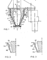
- the device has a housing 1 in which a machining tool 2 is accommodated. It sits on a shaft 3 which is driven by a motor 4 via a gear (not shown).
- the housing 1 has a working space 5 in which the processing tool 2 can be rotated and in which the supplied products can be processed and processed.
- the housing 1 has an outlet 6 through which the finished products are conveyed out of the work space 5.
- the working space 5 has a conveying section 7 that tapers in cross-section in the direction of the outlet 6, which merges in the conveying direction 8 of the products into a processing section 9 of the working space 5, which also tapers in the direction of the outlet 6, but more strongly than the conveying section 7
- the processing section 9 extends to the outlet 6, so that the products are processed from the transition into this processing section to the outlet from the outlet 6. The products can therefore be processed intensively, so that the processed product emerging from the outlet 6 has optimal properties.
- the processing section 9 is longer than the conveying section 7. This serves essentially only to convey the supplied products evenly into the processing section 9, so that the latter during the entire Processing time is filled.
- the cross-sectional tapering of the conveying section 7 can be achieved in that the side wall 10 of the housing 1 extends conically in the direction of the outlet 6 and the machining tool 2 can be cylindrical or also conically tapered in this section.
- the conveying section 7 is delimited by wall sections 10 of the housing 1 lying parallel to the axis of rotation 11 of the machining tool 2.
- the conveying section 7 is preferably delimited by a cylindrical housing part, while the part 12 of the machining tool 2 lying in the conveying section 7 is designed to widen conically in the direction of the outlet 6.
- This part 12 is formed by a truncated cone which is arranged centrally in the conveying section 7.
- the conveying section 7 is of annular design.
- the reduction in cross-section of the conveying section 7 of the working space 5 is relatively small, so that the products to be processed or processed are only slightly compressed in this area.
- the working part 13 of the machining tool 2 lying in the machining section 9 is also conical.
- the machining section 9 can in turn be delimited by a conical housing section and / or a conical part of the machining tool.
- the working part 13 of the processing tool 2 tapers in the direction of the outlet 6.
- the working part 13 extends to the outlet 6, see above that the entire length of the processing section is used to process the products.
- the machining section 9 is formed by wall sections 14 of the Ge lying obliquely to the axis of rotation 11 of the machining tool 2 housing 1, preferably limited by a conically tapering towards the outlet 6 housing part.
- the cone angle of the housing part 14 is larger than the cone angle of the working part 13 of the machining tool 2.
- the machining section 9 is delimited by two differently inclined cone surfaces.
- the cross-sectional tapering of the processing section 9 in the direction of the outlet 6 is substantially greater than in the conveying section 7, since the processing of the products is to take place in the processing section.
- the machining tool 2 forms a double cone with which the different cross-sectional changes in the two sections 7 and 9 of the working space 5 are achieved in a structurally very simple manner.
- the cone part 12 of the machining tool 2 is usually cooled and serves as a pure conveying part of the device.
- the lower working part 13 serves as a mixing or plasticizing part and is usually heated. In particular, this supports the plasticizing process in the processing section 9.
- the working part 13 can be kept at the same temperature as the product subject to plasticization by the heating, so that no undesired cooling occurs in the area of the working part 13 during the plasticizing process.
- the housing part 14 is also heated and equipped for this purpose with a heating jacket 15 or the like.
- the temperature can be adjustable, for example, from approximately 40 ° C. to approximately 800 ° C., so that the temperature which is most favorable for the respective machining process can be set.
- the working part 13 can also be heated in this temperature range.
- an ejection tool or a homogenizing screen 16 is attached to the housing part 14.
- the products are conveyed to this ejection tool or homogenizing screen 16 by centrifugal force and by reducing the viscosity of the product.
- the ejection tool 16 is used to shape the product to be ejected or to generate back pressure in connection with the centrifugal force delivery.
- the drive 4 is designed such that the machining tool 2 can be rotated at a speed between approximately 40 and approximately 200 rpm.
- the drive 4 can also be designed as a 2-stage drive, with which the machining tool 2 can be rotated, for example, five turns clockwise and two turns counterclockwise, in order to achieve a better homogenization or a centrifugal force ejection effect.
- the device can also be used for processing tough elastic products.
- the working part 13 is deep-frozen, for example with liquid nitrogen, in order to achieve a porosity of the product to be processed by deep-freezing.
- This viscoplastic product can then be easily broken up in the processing section 9 and, for example, processed into granules.
- the device can also be used as a mixer for pasty masses with any number of components.
- the housing part 14 is releasably attached to a flange 18 of the cylindrical housing part 10 via a flange 17.
- the machining tool 2 can also be removed after removing the housing part 14 can be exchanged for another processing tool.
- the cross-sectional tapering of the processing section 9 of the working space 5 when plasticizing must be different than, for example, when mixing the products.
- the housing part 14 and / or the machining tool 2 can thus be exchanged.
- the inner wall 19 of the housing part 14 is smooth in the embodiment according to FIG. 1.
- the conical surface of the working part 13 of the machining tool 2 is also smooth.
- the inner wall of the housing part can also be profiled, as shown in FIGS. 2 and 3.
- the inner wall 19a of the housing part 14a can have an irregular profile, so that the cross section of the processing section 9a does not decrease continuously in the direction of the outlet.
- the cross section of the processing section 9a can decrease very strongly, so that a very high compression of the product takes place in this area.
- the profile can be optimally adapted to the product to be processed and / or to the desired operation.
- the conical surface of the working part 13a is smooth in this exemplary embodiment, but can also have a profile.
- the inner wall 19a and / or the conical surface of the working part 13a can thus be profiled (FIGS. 2A and 2B).
- the inner wall 19b of the housing part 14b is provided with a corrugation 20.
- the device designed in this way is suitable for grinding tough, elastic products which have been frozen in the manner described above.
- the conical surface of the working part 13b is also smooth in this embodiment, but can also have a profile (FIGS. 3A and 3B).
- the products are finished in the work area 5, they can be passed directly from the outlet 6 into a press, between rollers and the like for further processing. An intermediate storage of the products is not necessary.
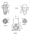
- the conical outer surface 21 of the working part 13c of the machining tool 2c is provided with brackets 22 which are spaced apart from one another over the length of the working part (FIGS. 4 and 8). They are used to hold profiled additional tools, e.g. 5 to 7 and 9 to 11 are shown.
- the brackets 22 are formed by dovetail-shaped annular grooves in the outer jacket 21 of the working part 13c.
- Part 12c of the machining tool 2c also has brackets 24 for additional tools on its outer jacket 23.
- the brackets are also formed by dovetail-shaped annular grooves which are spaced apart from one another over the length of the part 12c and in which the additional tools can be fastened.
- the corresponding number of additional tools can be releasably attached to the machining tool 2c both on the part 12c and on the working part 13c.
- the additional tools can be fastened in all brackets 22, 24.
- the free cross section of the conveying section 7 and / or the machining section 9 of the work area 5 can be reduced. This can be necessary in a simple manner for the required processing of the products
- the degree of cross-sectional tapering can be set. The various operations can thus be carried out optimally, so that the material emerging from the outlet 6 has optimal properties.
- the housing parts 10, 14 can also be provided with such holders, so that the additional tools can also be attached to the housing 1.
- the jacket of the machining tool 2c can be smooth. It is also possible to provide both the housing parts 10, 14 and the machining tool 2c with brackets, so that the additional tools are fastened to the housing 1 and to the machining tool 2c.
- the additional tool 25 has a base body 26 to be inserted in the respective holder 22, 24 and a profile section 27 which projects into the respective section of the working space 5.
- the profile section 27 has a triangular cross section and extends over the entire length of the additional tool 25 (FIG. 11). It can be curved in accordance with the processing tool 2c, so that adjacent additional tools 25 with an edge 28 of their profile sections 27 lie in a circle around the axis of rotation 11 of the processing tool 2c in the circumferential direction of the processing tool.
- the additional tools 25 can be designed such that adjacent additional tools connect to one another in the circumferential direction. However, they can also be spaced apart from one another in the circumferential direction.
- each groove is provided with an insertion section 31 (FIG. 8). It is adapted to a fastening part 32A (FIGS. 9-11) of the additional tool 25, which can be inserted into the groove 22, 24 through the insertion section 31.
- the fastening part 32 ⁇ has a cross section adapted to the grooves 22, 24 and has a rectangular outline (FIG. 11).
- the base body 26 of the additional tool 25 also has a rectangular outline, but is larger than the fastening part 32A (FIG. 11), which is preferably formed in one piece with the base body 26.
- the insertion section 31 of the grooves 22, 24 has the same outline as the fastening part 32A of the additional tools 25, so that they can be inserted comfortably and then moved into the desired position in the grooves.
- the grooves 22, 24 are designed such that the fastening parts 32A can be displaced in them despite the curved course of the grooves.
- Fastening or clamping are used to fix the additional tools 25 in the grooves 22, 24 screw, which are screwed into threaded holes 33 of the additional tools 25.
- the threaded bores 33 penetrate the fastening part 32A, the base body 26 and the profile section 27 of the additional tools 25 (FIGS. 9 to 11).
- the additional tool 25 is only provided with a single, centrally arranged threaded bore 33; Of course, the additional tool 25 can also be provided with two or more threaded bores 33.
- the fastening screw When the fastening screw is screwed in, it is supported on the bottom of the respective groove 22, 24, while the obliquely inclined surfaces 34, 35 (FIG. 8) against the corresponding inclined surfaces 36, 37 (FIG. 4) of the respective groove 22, 24 pulled and thus the additional tool is held non-positively on the machining tool 2.
- the additional tool 25d according to FIG. 6 has a profile section 27d which is approximately semicircular in cross section. It is - in accordance with the profile section 27 according to Figure 5 - integrally formed with the base body 26d.
- the profile section 27d lies in half the width of the base body 26d.
- the transition of the profile section 27a into the base body 26d takes place at a distance from the longitudinal edges 29, 30 of the base body.
- the additional tool 25d is otherwise of the same design as the embodiment according to FIGS. 5 and 9 to 11.
- the profile section 27 e of the profile tool 25e is formed by two adjoining parts 31 and 32 which are partially circular in cross section, which in turn lie in half the width of the base body 26e and at a distance therefrom Merging side edges 29e, 30e into it.
- the auxiliary tool 25e is the same configuration as the embodiment shown in F ig. 5 and 9 to 11.
- the additional tools can also have any other suitable cross-sectional configuration.
- the cross-sectional configuration of the working space 5 in the conveying section 7 and also in the processing section 9 can be optimally adapted to the respectively desired working conditions by means of a corresponding profiling.
- the axial spacing of the brackets 22, 24 from one another can also be selected to be of different sizes.
- the grooves can also have a square cross section.
- the grooves are provided with threaded holes into which the fastening screws for the additional tools are screwed. So that the additional tools can be fastened in several places along the circumference of the machining tool, at least some threaded bores are provided in some of the grooves.
- the machining tool 2f according to FIGS. 12 and 13 has brackets 22f, 24f which run in its longitudinal direction, preferably over the entire length. These brackets 22f, 24f are of the same design as in the embodiment according to FIGS. 4 and 8 ..
- the threaded bores 38 in the bottom of the grooves 22f, 24f are shown for the fastening screws of the additional tools. However, as described above, they can also be held non-positively in the grooves.
- the longitudinal grooves can only be provided in the working part 13f or only in part 12f, while the other part of the machining tool 2c can have circumferential grooves according to FIGS. 4 and 8.
- the holders 22g are formed by projections on the processing tool 2g, which are arranged distributed over the circumference of at least the working part 13g.
- the brackets 22g have a T-shaped cross section (Fig. 16) and stand with their foot 39 perpendicularly from the wall of the working part 13g, so that the web 40 of the bracket 22g is at a distance from the wall of the working part.
- the brackets 22 g are welded onto the working part 13g and take up additional tools 25g. They have a working section 41 projecting transversely from the working part 13 q , which connects to a holding section 42 lying transversely to it.
- the additional tool 25 g is C-shaped in cross section and engages around the web 40 of the holder 22g with play, so that the additional tool 25 g can simply be pushed onto the holder.
- at least one clamping screw 43 is provided, which is screwed through a threaded bore 44 in the C-web 45 of the mounting section 42 and is supported on the web 40 of the mounting 22g.
- the brackets 22g can also be designed so that they run over the entire length or the entire circumference of the working part 13 g .
- the brackets 22g can also be arranged helically.
- the device can be easily adjusted to different jobs.
- the interchangeable additional tools are easy to assemble and disassemble. In particular, it is no longer necessary to replace entire housing parts or the complete machining tool, so that the device can be converted to different work to be carried out in a cost-effective manner.
Landscapes
- Engineering & Computer Science (AREA)
- Mechanical Engineering (AREA)
- Physics & Mathematics (AREA)
- Thermal Sciences (AREA)
- Chemical & Material Sciences (AREA)
- Chemical Kinetics & Catalysis (AREA)
- Processing And Handling Of Plastics And Other Materials For Molding In General (AREA)
- Treatment Of Fiber Materials (AREA)
Applications Claiming Priority (4)
| Application Number | Priority Date | Filing Date | Title |
|---|---|---|---|
| DE19833334012 DE3334012A1 (de) | 1983-09-21 | 1983-09-21 | Vorrichtung zum bearbeiten von stoffen |
| DE3334012 | 1983-09-21 | ||
| DE19843434146 DE3434146A1 (de) | 1984-09-18 | 1984-09-18 | Vorrichtung zum bearbeiten von stoffen |
| DE3434146 | 1984-09-18 |
Publications (2)
| Publication Number | Publication Date |
|---|---|
| EP0148324A2 true EP0148324A2 (fr) | 1985-07-17 |
| EP0148324A3 EP0148324A3 (fr) | 1987-02-04 |
Family
ID=25814172
Family Applications (1)
| Application Number | Title | Priority Date | Filing Date |
|---|---|---|---|
| EP84111222A Withdrawn EP0148324A3 (fr) | 1983-09-21 | 1984-09-20 | Dispositif pour le travail de matériaux |
Country Status (1)
| Country | Link |
|---|---|
| EP (1) | EP0148324A3 (fr) |
Cited By (1)
| Publication number | Priority date | Publication date | Assignee | Title |
|---|---|---|---|---|
| EP1072561A3 (fr) * | 1999-07-29 | 2001-06-06 | Schott-Rohrglas GmbH | Guinand pour éviter des ondes dans le verre en fusion |
Family Cites Families (10)
| Publication number | Priority date | Publication date | Assignee | Title |
|---|---|---|---|---|
| FR319015A (fr) * | 1902-02-24 | 1902-10-31 | Mason Junior | Perfectionnements apportés à la fabrication des coussinets de machines ou autres et s'appliquant plus particulièrement aux tetes ou rouleaux à broyer ou moudre |
| NL200327A (fr) * | 1952-11-25 | |||
| US2857111A (en) * | 1955-01-21 | 1958-10-21 | Unipulver Ltd | Rotor blades and blade mounting means for grinding mills |
| GB843849A (en) * | 1957-11-22 | 1960-08-10 | Ici Ltd | Mixing apparatus |
| US3046603A (en) * | 1958-02-24 | 1962-07-31 | Research Corp | Method and apparatus for extrusion |
| DE1920259A1 (de) * | 1969-04-22 | 1970-11-12 | Kalle Ag | Kegelwalzwerk zum Mischen und Kneten plastischer Stoffe,insbesondere thermoplastischer Kunststoffe |
| US3632254A (en) * | 1970-01-14 | 1972-01-04 | Dart Ind Inc | Apparatus for producing fiber reinforced plastics |
| CA950448A (en) * | 1970-04-03 | 1974-07-02 | Agfa-Gevaert N.V. | Turbulent nucleate-grained silver-halide-reactants mixing method |
| US3785016A (en) * | 1971-05-27 | 1974-01-15 | Polrotor Inc | Apparatus for producing patterned pile fabrics |
| US3790328A (en) * | 1972-04-10 | 1974-02-05 | B Maxwell | Apparatus for feeding elastic melt extruders |
-
1984
- 1984-09-20 EP EP84111222A patent/EP0148324A3/fr not_active Withdrawn
Cited By (1)
| Publication number | Priority date | Publication date | Assignee | Title |
|---|---|---|---|---|
| EP1072561A3 (fr) * | 1999-07-29 | 2001-06-06 | Schott-Rohrglas GmbH | Guinand pour éviter des ondes dans le verre en fusion |
Also Published As
| Publication number | Publication date |
|---|---|
| EP0148324A3 (fr) | 1987-02-04 |
Similar Documents
| Publication | Publication Date | Title |
|---|---|---|
| DE2550969C2 (de) | Schneckenmaschine zum Homogenisieren von festen, flüssigen und zähviskosen Materialien | |
| DE3240165A1 (de) | Werkzeugmaschine zum gleichzeitigen fraesen mehrerer flaechen vom freien ende eines werkstuecks her | |
| EP0148966B2 (fr) | Dispositif de mélange et de cisaillement à cylindres en continu | |
| EP0221918A1 (fr) | Extrudeuse de produits alimentaires. | |
| DE3617175C2 (de) | Einrichtung zum Passieren, insbesondere Granulieren und/oder Sieben eines Gutes | |
| DE2404813A1 (de) | Verfahren und vorrichtung zur herstellung von granulaten aus pulverfoermigem, koernigem, teigfoermigem oder aehnlichem gut | |
| WO1995017293A1 (fr) | Dispositif de traitement de matieres thermoplastiques | |
| EP1620246A1 (fr) | Extrudeur a arbres multiples | |
| DE3334012A1 (de) | Vorrichtung zum bearbeiten von stoffen | |
| AT503334A1 (de) | Verfahren und vorrichtung zur plastifizierung von kunststoffmaterial | |
| DE2514307A1 (de) | Schneckengehaeuse fuer einen extruder oder eine spritzgiessmaschine | |
| EP0524176B1 (fr) | Dispositif de serrage vertical pour racleurs de bande transporteuse et similaire | |
| DE69704289T2 (de) | Verfahren und Vorrichtung zum Mischen mit kontinuierlichen Walzen von thermoplastischem Material | |
| EP0468338B1 (fr) | Appareil de broyage pour matières en vrac fibreuses ou granulaires comme des déchets | |
| DE69316824T2 (de) | Schnecke für Zweiwellenextruder und Zweiwellenextruder | |
| EP0548861B1 (fr) | Vis assemblée pour une extrudeuse utilisée dans l'industrie des céramiques | |
| DE1557167B2 (de) | Vorrichtung zum kontinuierlichen mischen und plastifizieren, insbesondere von kautschuk und kunststoffmassen | |
| DE1047417B (de) | Mahl- und Knetvorrichtung an Schneckenpressen fuer thermoplastische Massen | |
| DE1246223B (de) | Schneckenstrangpresse | |
| DE19534239A1 (de) | Verfahren zur Aufbereitung von Duroplasten | |
| EP0956901A1 (fr) | Arbre coupant muni d'éléments coupants pour appareil désintégrateur | |
| DE3434146A1 (de) | Vorrichtung zum bearbeiten von stoffen | |
| DE3807878C2 (de) | Handhobelmaschine | |
| EP0627980A1 (fr) | Extrudeuse a vis | |
| EP0884105A1 (fr) | Dispositif d'alimentation, de support, de palier et de montage pour appareils de broyage |
Legal Events
| Date | Code | Title | Description |
|---|---|---|---|
| PUAI | Public reference made under article 153(3) epc to a published international application that has entered the european phase |
Free format text: ORIGINAL CODE: 0009012 |
|
| AK | Designated contracting states |
Designated state(s): CH DE FR GB IT LI NL |
|
| PUAL | Search report despatched |
Free format text: ORIGINAL CODE: 0009013 |
|
| AK | Designated contracting states |
Kind code of ref document: A3 Designated state(s): CH DE FR GB IT LI NL |
|
| 17P | Request for examination filed |
Effective date: 19870930 |
|
| 18W | Application withdrawn |
Withdrawal date: 19900908 |
|
| STAA | Information on the status of an ep patent application or granted ep patent |
Free format text: STATUS: THE APPLICATION HAS BEEN WITHDRAWN |
|
| R18W | Application withdrawn (corrected) |
Effective date: 19900908 |