EP0148328A2 - Interrupteur électrique avec des contacts fixes formés par des parties de pistes conductrices - Google Patents
Interrupteur électrique avec des contacts fixes formés par des parties de pistes conductrices Download PDFInfo
- Publication number
- EP0148328A2 EP0148328A2 EP84111611A EP84111611A EP0148328A2 EP 0148328 A2 EP0148328 A2 EP 0148328A2 EP 84111611 A EP84111611 A EP 84111611A EP 84111611 A EP84111611 A EP 84111611A EP 0148328 A2 EP0148328 A2 EP 0148328A2
- Authority
- EP
- European Patent Office
- Prior art keywords
- contact
- fixed contacts
- tracks
- contacts
- conductor tracks
- Prior art date
- Legal status (The legal status is an assumption and is not a legal conclusion. Google has not performed a legal analysis and makes no representation as to the accuracy of the status listed.)
- Withdrawn
Links
- 239000004020 conductor Substances 0.000 claims abstract description 30
- 229910000510 noble metal Inorganic materials 0.000 abstract description 5
- 239000010931 gold Substances 0.000 description 13
- 229910052737 gold Inorganic materials 0.000 description 13
- PCHJSUWPFVWCPO-UHFFFAOYSA-N gold Chemical compound [Au] PCHJSUWPFVWCPO-UHFFFAOYSA-N 0.000 description 12
- 239000011248 coating agent Substances 0.000 description 6
- 238000000576 coating method Methods 0.000 description 6
- 239000004922 lacquer Substances 0.000 description 6
- RYGMFSIKBFXOCR-UHFFFAOYSA-N Copper Chemical compound [Cu] RYGMFSIKBFXOCR-UHFFFAOYSA-N 0.000 description 5
- 229910052802 copper Inorganic materials 0.000 description 5
- 239000010949 copper Substances 0.000 description 5
- 239000002966 varnish Substances 0.000 description 5
- 239000000463 material Substances 0.000 description 4
- 238000005530 etching Methods 0.000 description 3
- 238000000034 method Methods 0.000 description 3
- 229910052728 basic metal Inorganic materials 0.000 description 2
- 150000003818 basic metals Chemical class 0.000 description 2
- 239000010970 precious metal Substances 0.000 description 2
- 238000005299 abrasion Methods 0.000 description 1
- 238000005260 corrosion Methods 0.000 description 1
- 230000007797 corrosion Effects 0.000 description 1
- 238000011161 development Methods 0.000 description 1
- 230000018109 developmental process Effects 0.000 description 1
- 150000002343 gold Chemical class 0.000 description 1
- 239000011810 insulating material Substances 0.000 description 1
- 238000004519 manufacturing process Methods 0.000 description 1
- 238000001259 photo etching Methods 0.000 description 1
- 238000007747 plating Methods 0.000 description 1
Images
Classifications
-
- H—ELECTRICITY
- H01—ELECTRIC ELEMENTS
- H01H—ELECTRIC SWITCHES; RELAYS; SELECTORS; EMERGENCY PROTECTIVE DEVICES
- H01H1/00—Contacts
- H01H1/12—Contacts characterised by the manner in which co-operating contacts engage
- H01H1/36—Contacts characterised by the manner in which co-operating contacts engage by sliding
- H01H1/40—Contact mounted so that its contact-making surface is flush with adjoining insulation
- H01H1/403—Contacts forming part of a printed circuit
-
- H—ELECTRICITY
- H01—ELECTRIC ELEMENTS
- H01H—ELECTRIC SWITCHES; RELAYS; SELECTORS; EMERGENCY PROTECTIVE DEVICES
- H01H19/00—Switches operated by an operating part which is rotatable about a longitudinal axis thereof and which is acted upon directly by a solid body external to the switch, e.g. by a hand
- H01H19/005—Electromechanical pulse generators
Definitions
- the invention relates to an electrical switch, the fixed contacts of which are covered with a metallic layer of parts of conductor tracks on a circuit board and the movable contacts are designed as sliding contacts that can be moved on predetermined contact tracks via the fixed contacts on the circuit board, and in the case of a contact track a plurality of electrically connected fixed contacts are provided.
- a copper layer that is laminated onto the printed circuit board is usually used as the material for the conductor tracks and from which the conductor tracks are etched, preferably using a photo-etching process.
- the copper conductor tracks are not suitable as contacts for a switch, since the copper easily oxidizes, which inadmissibly increases the contact resistance between the movable and the fixed contacts.
- Such fixed contacts formed from conductor tracks are usually covered with a noble metal layer, for example with a gold layer.
- This gold layer is usually applied by a galvanic process.
- all conductor tracks on the printed circuit board are covered with a gold layer.
- the gold plating has a very small thickness, for example a few ⁇ m, the gold layer, which is essential for the fixed contacts, makes up a considerable part of the price of the entire printed circuit board.
- the covering varnish remains on the printed circuit board after the free pieces of the conductive path have been glazed, since removing them would cause additional work steps and costs and, at the same time, as corrosion protection for them parts of the conductor tracks covered with an EdeLMetal layer.
- the covering lacquer for the fee may not be applied to the locations of the circuit boards that correspond to the contact paths of the movable contacts.
- the material of the lacquer layer would get on the movable and fixed contacts due to abrasion when the switch was actuated, thus giving rise to considerable contact faults. It has therefore been accepted that in the area of the contact tracks of the movable contacts, it is not possible to cover the conductor tracks before the charge.
- the object of the invention is to achieve a further saving in EdeLmetaLL with switches of the type mentioned.
- the invention is based on the knowledge that there are numerous switches of the specified type in which a plurality of fixed contacts arranged on a contact track are electrically connected to one another.
- An example of such switches are the so-called coding switches.
- Such electrically connected fixed contacts lying on a common contact path have so far only been used as one continuous contact, which of course runs the entire length with a layer of precious metal, e.g. B. a gold layer must be provided.
- the conductor tracks in the switches in question are obtained by etching out a copper layer originally completely covering the circuit board, the connecting lines and supply lines for the fixed contacts on the circuit board can be routed as desired and can also have any shape and length without the material consumption thereby being reduced or the manufacturing effort changes.
- the etching baths are consumed less quickly, even with longer conductor tracks, since less copper has to be dissolved. With the invention, it is therefore possible to achieve a considerable saving in basic metal in the switches of the type mentioned without additional expenditure on process steps or material.
- the connecting lines for the contacts arranged on a contact path could be located directly on the edge of the con tact course run.
- the lacquer cover is arranged at a short distance from the contact track. However, this means that the noble metal coating extends somewhat beyond the contact path. If the connecting lines now ran directly after the contact track, they would still cover a narrow edge with EdeLmetaLL.
- the connecting lines are therefore arranged at a distance from the contact tracks and connected to the contacts via connecting webs. Then only narrow strips of the connecting webs are covered with the EdeLmetaLL layer after the contacts.
- the conductor tracks used to connect the fixed contacts of a contact track run approximately parallel to the contact track and the connecting webs run approximately perpendicular to the contact track.
- a further saving on EdeLmetaLL can be achieved by routing the supply lines to the fixed contacts so that the supply lines are arranged as perpendicular as possible to the contact path when the contact paths cross inevitably. Since, as mentioned at the beginning, there is an application of covering lacquer on the contact track is not possible, it is inevitable that the conductor tracks forming the supply lines are also gold-plated at the intersection points with the contact tracks. A right-angled crossing results in the smallest area to be gilded.
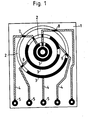
- a circuit pattern has been produced by etching on the circuit board 1 made of insulating material.
- the conductor tracks are shown partly black and partly hatched.
- the conductor tracks 3 drawn in black form the fixed contacts and the parts of the conductor tracks which are provided with an EdeLmetaLL harsh.
- the hatched conductor tracks 4 form the supply lines for the fixed contacts 3 and were covered during VergoLden.
- the ring-shaped connection contacts 5 are provided with a gold layer and serve to attach electrical supply lines for the switch.
- the contact tracks for the movable contacts are represented by the five circular tracks 2 which are concentric with one another.
- the parts of the contact tracks that are not filled in black are not per se visible on the circuit board. However, they are usually recognizable on the printed circuit board, since the ring-shaped zones between the contact tracks are printed with the covering varnish for the coating.
- the circuit board 1 is also printed with the covering varnish outside the contact track 2, with the exception of the connection contacts 5. Therefore, all conductor tracks present on the contact tracks are provided with a gold layer, that is to say not only the contact rings 5 but also the parts of the supply lines 4, which are one Cross the contact path. This is the case at the locations designated 6, 7, 8 and 9, where the supply lines 4 are inevitably covered with a gold layer.
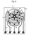
- FIG. 2 shows the same printed circuit board for a coding switch as FIG. 1, but here the printed conductors are arranged according to the invention, which leads to a considerable saving in GoLd.
- the individual contacts are present on each contact track in the embodiment according to FIG. 2, while the electrical connection of the individual interconnected contacts runs between the contact tracks.
- the connecting lines designated 10, 11, 12, 13 and 14 are arranged between the individual contacts. Since these can be covered between the contact tracks and outside of the contact tracks with a lacquer before the gold coating, there is a substantial saving in gold, since the areas to be gold-plated are considerably smaller, which is readily shown by a comparison with the black area parts in FIG. 1 .
- the connecting lines 10, 11, 12, 13 and 14 are arranged approximately parallel to and at a distance from the contact tracks 2 and are connected to the fixed contacts 3 by connecting webs 15 running approximately perpendicular to the contact tracks 2.
Landscapes
- Contacts (AREA)
- Manufacture Of Switches (AREA)
- Coupling Device And Connection With Printed Circuit (AREA)
- Rotary Switch, Piano Key Switch, And Lever Switch (AREA)
Applications Claiming Priority (2)
| Application Number | Priority Date | Filing Date | Title |
|---|---|---|---|
| DE3336130 | 1983-10-05 | ||
| DE19833336130 DE3336130A1 (de) | 1983-10-05 | 1983-10-05 | Elektrischer schalter |
Publications (2)
| Publication Number | Publication Date |
|---|---|
| EP0148328A2 true EP0148328A2 (fr) | 1985-07-17 |
| EP0148328A3 EP0148328A3 (fr) | 1988-03-23 |
Family
ID=6210999
Family Applications (1)
| Application Number | Title | Priority Date | Filing Date |
|---|---|---|---|
| EP84111611A Withdrawn EP0148328A3 (fr) | 1983-10-05 | 1984-09-28 | Interrupteur électrique avec des contacts fixes formés par des parties de pistes conductrices |
Country Status (4)
| Country | Link |
|---|---|
| US (1) | US4578547A (fr) |
| EP (1) | EP0148328A3 (fr) |
| JP (1) | JPS6097518A (fr) |
| DE (1) | DE3336130A1 (fr) |
Families Citing this family (8)
| Publication number | Priority date | Publication date | Assignee | Title |
|---|---|---|---|---|
| US5315077A (en) * | 1993-04-05 | 1994-05-24 | Bourns, Inc. | Rotary switch including cam operated flexible contacts |
| DE19919395A1 (de) * | 1998-04-29 | 1999-11-04 | Capax B V | Schalter für elektrische Werkzeuge mit integrierten Schaltkontakten |
| US6288653B1 (en) * | 1998-12-22 | 2001-09-11 | Yun Ning Shih | Curved surface signal pick-up device |
| EP1190830B1 (fr) * | 1998-12-24 | 2004-07-14 | Teikoku Tsushin Kogyo Co. Ltd. | Méthode pour former un motif de commutateur sur un substrat de commutateur |
| DE102009012145B4 (de) * | 2009-03-06 | 2014-02-20 | Abb Technology Ag | Verfahren zur Herstellung von Bauteilen, sowie Bauteile selbst |
| USD545769S1 (en) * | 2006-02-17 | 2007-07-03 | Stora Enso Ab | Switch |
| JP4622879B2 (ja) * | 2006-02-17 | 2011-02-02 | パナソニック株式会社 | 回転操作形エンコーダ |
| CN102306582A (zh) * | 2011-07-11 | 2012-01-04 | 浙江正泰机床电气制造有限公司 | 一种旋转型万能开关 |
Family Cites Families (10)
| Publication number | Priority date | Publication date | Assignee | Title |
|---|---|---|---|---|
| US2896033A (en) * | 1955-01-27 | 1959-07-21 | Daystrom Inc | Printed circuit assembly |
| JPS5242003B2 (fr) * | 1971-12-06 | 1977-10-21 | ||
| DE7310839U (de) * | 1973-03-22 | 1976-08-12 | Reck, Dieter, 7250 Leonberg | Codierschalter |
| US3794784A (en) * | 1973-05-07 | 1974-02-26 | Atlantic Richfield Co | Rotary wafer switch having rotor mounted, spiral arranged axial bridging contacts |
| DE2441469C3 (de) * | 1974-08-29 | 1980-12-04 | Hartmann & Braun Ag, 6000 Frankfurt | Elektrischer Drehschalter in geschlossener Bauweise |
| JPS5147271A (en) * | 1974-10-18 | 1976-04-22 | Matsushita Electric Industrial Co Ltd | Insatsusuitsuchipurintokiban |
| US4038504A (en) * | 1975-11-19 | 1977-07-26 | A.C. Nielsen Company | Rotary, printed circuit wafer switch and method for adjusting |
| FR2336782A1 (fr) * | 1975-12-22 | 1977-07-22 | Radiotechnique Compelec | Commutateurs rotatifs codeurs |
| US4246453A (en) * | 1979-07-12 | 1981-01-20 | Electro Audio Dynamics, Inc. | Switch |
| DE3040546C2 (de) * | 1980-10-28 | 1983-04-07 | Siemens AG, 1000 Berlin und 8000 München | Codierschalter |
-
1983
- 1983-10-05 DE DE19833336130 patent/DE3336130A1/de not_active Withdrawn
-
1984
- 1984-09-28 EP EP84111611A patent/EP0148328A3/fr not_active Withdrawn
- 1984-10-01 US US06/656,700 patent/US4578547A/en not_active Expired - Fee Related
- 1984-10-04 JP JP59207248A patent/JPS6097518A/ja active Pending
Also Published As
| Publication number | Publication date |
|---|---|
| DE3336130A1 (de) | 1985-04-18 |
| US4578547A (en) | 1986-03-25 |
| JPS6097518A (ja) | 1985-05-31 |
| EP0148328A3 (fr) | 1988-03-23 |
Similar Documents
| Publication | Publication Date | Title |
|---|---|---|
| DE3610821C2 (fr) | ||
| DE2911620C2 (de) | Verfahren zum Herstellen von leitenden durchgehenden Bohrungen in Schaltungsplatten | |
| DE60218961T2 (de) | Einpress-Sammelschiene für Leistungsversorgung | |
| EP0374648B1 (fr) | Dispositif de connexion d'un câble électrique | |
| EP0762817A1 (fr) | Blindage pour des plaquettes de circuit | |
| DE2247902A1 (de) | Gedruckte schaltungsplatte und verfahren zu deren herstellung | |
| DE19638681C2 (de) | Verfahren zur Fertigung eines elektrischen Verteilerkastens | |
| DE19511300A1 (de) | Antennenstruktur | |
| DE2103064A1 (de) | Vorrichtung zur Herstellung von Modulelementen | |
| DE3502744C2 (fr) | ||
| DE60128537T2 (de) | Zusammenbau zur verbindung von mindestens zwei gedruckten schaltungen | |
| DE2604111A1 (de) | Streifenband-uebertragungsleitung | |
| EP0017979B1 (fr) | Réseau électrique et procédé pour sa fabrication | |
| EP0148328A2 (fr) | Interrupteur électrique avec des contacts fixes formés par des parties de pistes conductrices | |
| DE1085209B (de) | Gedruckte elektrische Leiterplatte | |
| DE8912914U1 (de) | Leiteranordnung aus gestanzten Leiterbahnen | |
| DE102015115819A1 (de) | Leiterbrückenelement sowie Bestückungsgurt und Leiterplatten mit einem solchen | |
| DE1930642A1 (de) | Leiterplatte zum Aufnehmen und Verbinden elektrischer Bauelemente | |
| DE2611871A1 (de) | Elektrische schaltungsbaugruppe in mehrschichtbauweise und verfahren zu deren herstellung | |
| WO1985000085A1 (fr) | Carte imprimee pour le montage en surface de circuits integres miniature et procede de fabrication de telles cartes imprimees | |
| EP0278485B1 (fr) | Méthode de fabrication d'une plaquette utilisable pour la digitalisation | |
| DE4405919A1 (de) | Mit galvanisierten , untereinander über Stanzgitter verbundenen Anschlüssen versehene elektrische Baugruppe sowie Herstellungsverfahren hierzu | |
| DE69400391T2 (de) | Versorgungsverteilung-Busschiene für Komponentenunterlage, die Komponentenunterlage und Verteilungsbrücken zum Verbinden der Busschiene mit der Unterlage | |
| DE2103693A1 (de) | Verfahren und Vorrichtung zum Ver binden von Anschlußklemmen | |
| DE69504301T2 (de) | Leiterplatte mit speziell ausgeführten anschlussflächen |
Legal Events
| Date | Code | Title | Description |
|---|---|---|---|
| PUAI | Public reference made under article 153(3) epc to a published international application that has entered the european phase |
Free format text: ORIGINAL CODE: 0009012 |
|
| AK | Designated contracting states |
Designated state(s): BE CH DE FR GB IT LI |
|
| RAP1 | Party data changed (applicant data changed or rights of an application transferred) |
Owner name: STANDARD ELEKTRIK LORENZ AKTIENGESELLSCHAFT Owner name: ALCATEL N.V. |
|
| PUAL | Search report despatched |
Free format text: ORIGINAL CODE: 0009013 |
|
| AK | Designated contracting states |
Kind code of ref document: A3 Designated state(s): BE CH DE FR GB IT LI |
|
| RAP3 | Party data changed (applicant data changed or rights of an application transferred) |
Owner name: ALCATEL N.V. Owner name: STANDARD ELEKTRIK LORENZ AKTIENGESELLSCHAFT |
|
| STAA | Information on the status of an ep patent application or granted ep patent |
Free format text: STATUS: THE APPLICATION IS DEEMED TO BE WITHDRAWN |
|
| 18D | Application deemed to be withdrawn |
Effective date: 19880926 |
|
| RIN1 | Information on inventor provided before grant (corrected) |
Inventor name: OESTERLE, HERMANN FRIEDRICH Inventor name: GUENTHER, HORST HERMANN |