EP0148599A2 - Buse de combustible - Google Patents
Buse de combustible Download PDFInfo
- Publication number
- EP0148599A2 EP0148599A2 EP84308583A EP84308583A EP0148599A2 EP 0148599 A2 EP0148599 A2 EP 0148599A2 EP 84308583 A EP84308583 A EP 84308583A EP 84308583 A EP84308583 A EP 84308583A EP 0148599 A2 EP0148599 A2 EP 0148599A2
- Authority
- EP
- European Patent Office
- Prior art keywords
- swirler
- nozzle
- annulus
- fuel
- swirl
- Prior art date
- Legal status (The legal status is an assumption and is not a legal conclusion. Google has not performed a legal analysis and makes no representation as to the accuracy of the status listed.)
- Withdrawn
Links
Images

Classifications
-
- F—MECHANICAL ENGINEERING; LIGHTING; HEATING; WEAPONS; BLASTING
- F23—COMBUSTION APPARATUS; COMBUSTION PROCESSES
- F23D—BURNERS
- F23D17/00—Burners for combustion simultaneously or alternately of gaseous or liquid or pulverulent fuel
- F23D17/002—Burners for combustion simultaneously or alternately of gaseous or liquid or pulverulent fuel gaseous or liquid fuel
-
- F—MECHANICAL ENGINEERING; LIGHTING; HEATING; WEAPONS; BLASTING
- F23—COMBUSTION APPARATUS; COMBUSTION PROCESSES
- F23D—BURNERS
- F23D11/00—Burners using a direct spraying action of liquid droplets or vaporised liquid into the combustion space
- F23D11/005—Burners using a direct spraying action of liquid droplets or vaporised liquid into the combustion space with combinations of different spraying or vaporising means
- F23D11/007—Burners using a direct spraying action of liquid droplets or vaporised liquid into the combustion space with combinations of different spraying or vaporising means combination of means covered by sub-groups F23D11/10 and F23D11/24
-
- F—MECHANICAL ENGINEERING; LIGHTING; HEATING; WEAPONS; BLASTING
- F23—COMBUSTION APPARATUS; COMBUSTION PROCESSES
- F23D—BURNERS
- F23D14/00—Burners for combustion of a gas, e.g. of a gas stored under pressure as a liquid
- F23D14/20—Non-premix gas burners, i.e. in which gaseous fuel is mixed with combustion air on arrival at the combustion zone
- F23D14/22—Non-premix gas burners, i.e. in which gaseous fuel is mixed with combustion air on arrival at the combustion zone with separate air and gas feed ducts, e.g. with ducts running parallel or crossing each other
- F23D14/24—Non-premix gas burners, i.e. in which gaseous fuel is mixed with combustion air on arrival at the combustion zone with separate air and gas feed ducts, e.g. with ducts running parallel or crossing each other at least one of the fluids being submitted to a swirling motion
Definitions
- the invention relates to fuel nozzles and more particularly to fuel nozzles suitable for mixing air with both liquid and gaseous fuels.
- turbine engines used in industrial applications were generally fueled by petroleum based, liquid fuels or, alternatively, by natural gas.
- the fuel nozzles, as well as the engine itself were compatible with only one of these types of fuels.
- the gas was injected in divergent directions from a plurality of holes and mixed with a swirling air blast.
- fuel oil was divided into a primary flow and a secondary flow. The primary flow was pressure atomized and the secondary flow was atomized by a swirling air blast.
- Specific examples of such prior fuel nozzles are shown and described in U.S. Patents 3,013,732; 3,912,164; 3,980,233; and 4,365,753.
- turbine engines were powered by one type of fuel exclusively; there was no freedom to choose between available fuels on the basis of cost or availabiltiy.
- a fuel nozzle that provides a mixture of fuel and air at an output oriface, characterised in that the nozzle comprises:
- the atomizing means includes a primary fuel atomizer located in an internal cavity of the body, and a swirl plate that is maintained between the body and the intermediate swirler.
- the swirl plate provides a passageway between a secondary fuel supply annulus in the body and the discharge oriface of the nozzle.
- the primary fuel atomizer co-operates with the body to provide an inner air annulus between the atomizer and the cavity wall.
- the body includes a plurality of passageways, each passageway having an opening in the wall of the internal cavity and an opening in the peripheral surface of the body and being obliquely aligned with respect to the longitudinal axis of the nozzle such that a swirled flow of air is provided to the inner air annulus from the periphery of the body.
- One or both of the outer air swirler and the intermediate swirler may include a plurality of swirl vanes that are circumferentially spaced and canted with respect to the longitudinal axis of the nozzle to swirl air or fuel in the intermediate annulus, and to swirl air in the outer air swirl annulus.
- a fuel nozzle that provides a mixture of fuel and air through an output oriface, characterised in that the nozzle comprises:
- a fuel nozzle comprising:
- a nozzle assembly 10 includes a holder 12 that envelops tubes 14 and 16 in a central conduit 18.
- a sidewall 19 of the holder 12 is provided with a passageway 20 having a hole 21 at the end thereof.
- the holder 12 secures a nozzle 22 and, at the other end, the holder 12 is connected to a manifold 24.
- the manifold 24 is provided with inlet fittings 26, 28, 30 and 32 for respective connection to supplies of pressurized primary liquid fuel, pressurized secondary liquid fuel, natural gas and water.
- the inlet fittings 26 and 28 are respectively connected to the tubes 14 and 16, the inlet fitting 30 is connected to the conduit 18, and the inlet fitting 32 is connected to the passageway 20.
- the nozzle 22 is provided with pressurized liquid fuel through the tube 14, pressurized liquid fuel through the tube 16, natural gas through the conduit 18, and water through the passageway 20.
- the nozzle 22 is connected to the holder 12 at one end and at the other end is provided with a discharge oriface 33.
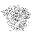
- the nozzle 22 includes a body 34 having an internal cavity 36 aligned with the longitudinal centre axis A-A' of the nozzle 22.
- the body 34 has an outer peripheral surface 38 and the cavity 36 has a cavity wall 40.
- the body 34 is also provided with typically four or more passageways 42 that are regularly spaced circumferentially around the body 34.
- Each of the passageways 42 connects a respective opening or port 44 in the peripheral surface 38 with a respective opening or port 46 in the cavity wall 40.
- the passageways 42 are aligned obliquely on non-intersecting axes with respect to the longitudinal centre axis A-A of the nozzle 22.
- the passageways 42 thus co-operate to provide a swirled flow of air to the internal cavity 36 from the peripheral surface 38.
- the body 34 is provided with at least one secondary fuel bore 48 and a gas bore 49.
- a retainer 50 is connected to one end of the body 34 and co-operates with the body 34 to form an annular secondary fuel chamber 51.
- a primary atomizer 52 of the pressure atomization type as well known in the art is mounted in the retainer 50 such that it projects into the internal cavity 36 of the body 34 and co-operates with the internal wall 40 to form an inner air annulus 53 that is in communication with the ports 46.
- the retainer 50 is also connected to the tubes 14 and 16 of the holder 12.
- the tube 14 extends through the retainer 50 and is in fluid communication with the primary atomizer 52.
- the tube 16 is in communication with the annular secondary fuel chamber 51.
- a cover that includes a housing 54 and a shroud 56 circumferentially surrounds the body 34.
- the housing 54 is a generally cylindrical member that is connected to the body 34 by a plurality of posts 57 and co-operates with the body 34 to form an annular cavity 58 therebetween.
- the housing 54 is provided with a cylindrical rim 59 that is in crimped engagement with a plurality of longitudinal slots 59a in the shroud 56.
- the rim 59 co-operates with the slots 59a of the shroud 56 to prevent rotation of the shroud 56 with respect to the housing 54.
- An air swirler 60 also circumferentially surrounds the body 34 and is radially located from the central longitudinal axis A-A' between the shroud 56 and the body 34.
- the air swirler 60 co-operates with the shroud 56 to form an outer air annulus 59b. More specifically, the air swirler 60 includes an annular ring 61 located adjacent to the body 34 and a cone 61a that is integrally connected to the discharge end of the annular ring 61.
- the cone 61a co-operates with the shroud 56 to define the air annulus 59b.
- the swirler 60 further includes a plurality of swirl vanes 62 that are regularly spaced circumferentially around the peripheral surface of the annular ring 61.
- the swirl vanes 62 are located adjacent the shroud 56 and between the shroud 56 and the annular ring 61 such that the annulus 59b is in communication between the vanes 62 with the annular cavity 58 formed between the body 34 and the housing 54.
- the vanes 62 are canted with respect to the longitudinal axis A-A' such that a swirling motion is imparted to air flowing into the annulus 59b from the annular cavity 58.
- the adjacent edges of the swirl vanes 62 are fastened to the shroud 56 by brazing or other equivalent means to secure the swirler 60 and the shroud 56.
- An intermediate swirler 64 also circumferentially surrounds the body 34.
- the intermediate swirler 64 is radially located from the central axis A-A' between the swirler 60 and the body 34 and is screwthreaded onto the body 34.
- the intermediate swirler 64 co-operates with the air swirler 60 to form an intermediate annulus 66 of the discharge oriface 33.
- the intermediate swirler 64 also co-operates with the swirler 60 and with the body 34 to form an annular cavity 68 that is in communication with the gas bore 49 and the central conduit 18.
- the intermediate swirler 64 includes an annular ring 69 located adjacent the body 34 and screwthreaded thereto.
- the intermediate swirler also includes a cone 69a that is integrally connected to the discharge end of the annular ring 69.
- the cone 69a co-operates with the cone 61a to define an intermediate annulus 66.
- the intermediate swirler 64 is further provided with a plurality of swirl vanes 70 that are regularly spaced circumferentially around the peripheral surface of annular ring 69. Swirl vanes 70 are located adjacent the annular ring 61 of the air swirler 60 such that the annulus 66 is in communication with the annular cavity 68 between the vanes 70.
- the swirl vanes 70 are canted with respect to the longitudinal axis A-A' such that a swirling motion is imparted to fluid flowing into the annulus 66 from the cavity 68.
- the edges of the swirl vanes 70 adjacent the annular ring 61 of the air swirler 60 are fastened thereto by brazing or other equivalent means to secure the swirler 60 with respect to the intermediate swirler 64.
- the intermediate swirler 64, the outer air swirler 60 and the shroud 56 are secured together and are threadedly connected to the body 34 at the intermediate air swirler 64. Rotation of the intermediate swirler 64 on the threads is prevented through connection with the housing 54 through the air swirler 60 and the shroud 56.
- the housing 54 is rigidly connected to the body 34 by the posts 57 and is crimped to the shroud 56 at the rim 59 and the slots 59a.
- Flexible metal seals 71 and 71a are located between the body 34 and respective end faces of the annular ring 61 and the annular ring 69. Thus, the metal seals 71 and 71a respectively provide a fluid seal between the body 34 and the outer air swirler 60 and between the body 3.4 and the intermediate swirler 64.
- a swirl plate 72 is maintained between a shoulder 74 of the swirler 64 and a shoulder 76 of the body 34.
- the swirl plate 72 co-operates with the swirler 64 and the body 34 to define an annular cavity 78 that is in communication with the secondary fuel bore 48, the annular secondary fuel chamber 51, and the tube 16.
- the swirl plate 72 is provided with a plurality of holes 80 such that fuel in the annular cavity 78 can flow past the swirl plate 72 to the discharge oriface 33.
- the swirl holes 80 are circumferentially spaced around the swirl plate 72 and are canted with respect to the longitudinal axis A-A' such that swirling motion is imparted to fuel flowing past the swirl plate 72 to the discharge oriface 33.
- the nozzle assembly shown in Figures 1 and 2 has various operational modes in which it provides liquid fuel, natural gas, or various combinations thereof either with or without water mixed therein.
- the liquid fuel is provided under pressure to the primary atomizer 52 through the tube 14.
- the primary atomizer 52 provides a primary spray pattern through the nozzle discharge oriface 33.
- liquid fuel is provided through the tube 16, the secondary fuel chamber 51, the secondary fuel bore 48 and the annular cavity 78 to the swirl plate 72. From the swirl plate 72, the secondary fuel flows out of the discharge oriface 33 in a swirled pattern.
- the primary and swirled secondary fuel spray patterns with swirled air better to atomize and define the spray pattern and retard accumulation of carbon on surfaces of the nozzle 22 adjacent the discharge oriface 33.
- this is accomplished by supplying high velocity or pressurized air to the annular cavity 58.
- the air in the cavity 58 is swirled by the vanes 62 as it flows into the outer air annulus 59b such that it forms an outer swirling air flow at the discharge oriface 33.
- the air in the cavity 58 flowing to the discharge oriface 33 through the passageways 42 is swirled by the passageways 42 as it flows into the inner air annulus 53 to further define and atomize the spray pattern.
- the gas is supplied through the conduit 18, the bore 49, and the annular cavity 68 to the intermediate annulus 66.
- the swirl vanes 70 cause the gas in the annulus 66 to exit at the discharge oriface 33 in a swirling pattern.
- the nozzle 22 can supply liquid fuel and gas simultaneously in the manner described above by supplying liquid fuel to the tubes 14 and 16 and gas to the conduit 18.
- the swirling flow of gas from the intermediate annulus 66 supplements the swirling air flow from the outer air annulus 59b and the inner air annulus 53 further to improve atomization of the liquid spray pattern.
- the inlet fitting 30 and the conduit 18 can be coupled to a supply of high velocity or pressurized air instead of a gas supply.
- the intermediate annulus 66 would provide a swirling air flow pattern that would supplement the swirling air flow from the outer air annulus 59b and the inner air annulus 53 further to improve the definition and atomization of the liquid spray pattern from the primary atomizer 52 and the swirl plate 72.
- Liquid fuel injected through the primary atomizer 52, or the swirl plate 72 as well as gaseous fuel injected through the intermediate annulus 66 can be mixed with other additives.
- the additives are provided through the hole 21 which is in communication with the annular cavity 58.
- the additives are mixed and atomized in the annular cavity 58, the outer air annulus 59b and the inner air annulus 53 and injected with the swirled air through the discharge oriface 33.
- fuel was supplied only to the swirl plate 72 and the spray pattern atomized by an air swirl from the outer air annulus 59b and the inner air annulus 53.
- a fuel flow rate of 11.8 kilos (26 pounds) per hour of 12 x 10 -6 sq. m/sec (12 centistokes) viscosity fluid and an air pressure drop of 747 Pa (3 inches of water ) across the vanes 62 resulted in a mean drop diameter of 90 micrometers, Sauter Mean Diameter.
- air at 27.56 k Pa (4.0 psi) was additionally supplied to the conduit 18, the air swirl from the intermediate annulus 66 caused a reduction in a mean drop diameter to 23 micrometers, Sauter Mean Diameter.
Landscapes
- Engineering & Computer Science (AREA)
- Chemical & Material Sciences (AREA)
- Combustion & Propulsion (AREA)
- Mechanical Engineering (AREA)
- General Engineering & Computer Science (AREA)
- Nozzles For Spraying Of Liquid Fuel (AREA)
- Nozzles (AREA)
- Fuel-Injection Apparatus (AREA)
Applications Claiming Priority (2)
| Application Number | Priority Date | Filing Date | Title |
|---|---|---|---|
| US56266883A | 1983-12-19 | 1983-12-19 | |
| US562668 | 1983-12-19 |
Publications (2)
| Publication Number | Publication Date |
|---|---|
| EP0148599A2 true EP0148599A2 (fr) | 1985-07-17 |
| EP0148599A3 EP0148599A3 (fr) | 1985-12-04 |
Family
ID=24247252
Family Applications (1)
| Application Number | Title | Priority Date | Filing Date |
|---|---|---|---|
| EP84308583A Withdrawn EP0148599A3 (fr) | 1983-12-19 | 1984-12-10 | Buse de combustible |
Country Status (2)
| Country | Link |
|---|---|
| EP (1) | EP0148599A3 (fr) |
| JP (1) | JPS60156970A (fr) |
Cited By (7)
| Publication number | Priority date | Publication date | Assignee | Title |
|---|---|---|---|---|
| GB2198521A (en) * | 1986-12-10 | 1988-06-15 | Mtu Muenchen Gmbh | Gas turbine fuel injector |
| US6253555B1 (en) | 1998-08-21 | 2001-07-03 | Rolls-Royce Plc | Combustion chamber comprising mixing ducts with fuel injectors varying in number and cross-sectional area |
| EP2090830A1 (fr) * | 2008-02-13 | 2009-08-19 | ALSTOM Technology Ltd | Agencement d'alimentation en carburant |
| FR2961858A1 (fr) * | 2010-06-29 | 2011-12-30 | Gen Electric | Systeme d'injection d'additif destine a un moteur a turbine |
| US8365534B2 (en) | 2011-03-15 | 2013-02-05 | General Electric Company | Gas turbine combustor having a fuel nozzle for flame anchoring |
| EP2402581A3 (fr) * | 2010-06-29 | 2014-12-24 | General Electric Company | Système d'injection d'additif pour un moteur à turbine et procédés d'assemblage associés |
| US9500369B2 (en) | 2011-04-21 | 2016-11-22 | General Electric Company | Fuel nozzle and method for operating a combustor |
Family Cites Families (5)
| Publication number | Priority date | Publication date | Assignee | Title |
|---|---|---|---|---|
| US1536046A (en) * | 1920-08-07 | 1925-05-05 | Alfred R Anthony | Oil burner |
| CH276515A (de) * | 1948-05-05 | 1951-07-15 | Rolls Royce | Brennstoffeinspritzvorrichtung für flüssigen Brennstoff. |
| GB1141536A (en) * | 1966-05-19 | 1969-01-29 | Rover Co Ltd | Liquid fuel nozzle |
| US3638865A (en) * | 1970-08-31 | 1972-02-01 | Gen Electric | Fuel spray nozzle |
| AT315342B (de) * | 1972-06-23 | 1974-05-27 | Elf Union | Emulsionsbrenner |
-
1984
- 1984-12-10 EP EP84308583A patent/EP0148599A3/fr not_active Withdrawn
- 1984-12-19 JP JP26821884A patent/JPS60156970A/ja active Pending
Cited By (10)
| Publication number | Priority date | Publication date | Assignee | Title |
|---|---|---|---|---|
| GB2198521A (en) * | 1986-12-10 | 1988-06-15 | Mtu Muenchen Gmbh | Gas turbine fuel injector |
| GB2198521B (en) * | 1986-12-10 | 1990-05-02 | Mtu Muenchen Gmbh | Fuel injector |
| US6253555B1 (en) | 1998-08-21 | 2001-07-03 | Rolls-Royce Plc | Combustion chamber comprising mixing ducts with fuel injectors varying in number and cross-sectional area |
| EP2090830A1 (fr) * | 2008-02-13 | 2009-08-19 | ALSTOM Technology Ltd | Agencement d'alimentation en carburant |
| AU2009200205B2 (en) * | 2008-02-13 | 2011-10-06 | Ansaldo Energia Ip Uk Limited | Fuel supply arrangement for a gas turbine |
| US8196409B2 (en) | 2008-02-13 | 2012-06-12 | Alstom Technology Ltd | Gas turbine engine fuel supply arrangement using plural distinct fuels |
| FR2961858A1 (fr) * | 2010-06-29 | 2011-12-30 | Gen Electric | Systeme d'injection d'additif destine a un moteur a turbine |
| EP2402581A3 (fr) * | 2010-06-29 | 2014-12-24 | General Electric Company | Système d'injection d'additif pour un moteur à turbine et procédés d'assemblage associés |
| US8365534B2 (en) | 2011-03-15 | 2013-02-05 | General Electric Company | Gas turbine combustor having a fuel nozzle for flame anchoring |
| US9500369B2 (en) | 2011-04-21 | 2016-11-22 | General Electric Company | Fuel nozzle and method for operating a combustor |
Also Published As
| Publication number | Publication date |
|---|---|
| EP0148599A3 (fr) | 1985-12-04 |
| JPS60156970A (ja) | 1985-08-17 |
Similar Documents
| Publication | Publication Date | Title |
|---|---|---|
| EP0677704B1 (fr) | Brûleur | |
| US6021635A (en) | Dual orifice liquid fuel and aqueous flow atomizing nozzle having an internal mixing chamber | |
| CA2379312C (fr) | Systeme de pulverisation pneumatique de carburant | |
| US3684186A (en) | Aerating fuel nozzle | |
| US4337618A (en) | Gas turbine engine fuel burners | |
| US6282904B1 (en) | Full ring fuel distribution system for a gas turbine combustor | |
| US5467926A (en) | Injector having low tip temperature | |
| US4107918A (en) | Combustion assembly | |
| US3904119A (en) | Air-fuel spray nozzle | |
| EP1323982A1 (fr) | Buse de combustible pour une turbine à gaz | |
| GB2204121A (en) | Low coke fuel injector e g for a gas turbine engine | |
| EP1058063A1 (fr) | Injecteur de carburant liquide pour brûleurs de turbines à gaz | |
| GB2131154A (en) | Fuel injector assembly with water or auxiliary fuel capability | |
| CN113137636B (zh) | 双油路喷嘴结构 | |
| JP2009192214A (ja) | ガスタービンエンジン用の燃料ノズル及びその製造方法 | |
| US4311277A (en) | Fuel injector | |
| US20180266694A1 (en) | Dual-Fuel Fuel Nozzle with Liquid Fuel Tip | |
| EP0148599A2 (fr) | Buse de combustible | |
| US4967562A (en) | Turbine engine with high efficiency fuel atomization | |
| US20130031905A1 (en) | Fuel nozzle | |
| US5636981A (en) | Fuel oil burner | |
| US4453384A (en) | Fuel burners and combustion equipment for use in gas turbine engines | |
| US5269495A (en) | High-pressure atomizing nozzle | |
| RU2304252C2 (ru) | Усовершенствованная форсунка для жидкого топлива для горелок газовых турбин | |
| CN107166435A (zh) | 一种多燃料喷嘴、燃料喷出系统及其涡轮发动机 |
Legal Events
| Date | Code | Title | Description |
|---|---|---|---|
| PUAI | Public reference made under article 153(3) epc to a published international application that has entered the european phase |
Free format text: ORIGINAL CODE: 0009012 |
|
| AK | Designated contracting states |
Designated state(s): DE GB |
|
| PUAL | Search report despatched |
Free format text: ORIGINAL CODE: 0009013 |
|
| AK | Designated contracting states |
Designated state(s): DE GB |
|
| RAP1 | Party data changed (applicant data changed or rights of an application transferred) |
Owner name: PARKER HANNIFIN CORPORATION |
|
| 17P | Request for examination filed |
Effective date: 19860524 |
|
| 17Q | First examination report despatched |
Effective date: 19870202 |
|
| STAA | Information on the status of an ep patent application or granted ep patent |
Free format text: STATUS: THE APPLICATION IS DEEMED TO BE WITHDRAWN |
|
| 18D | Application deemed to be withdrawn |
Effective date: 19880510 |
|
| RIN1 | Information on inventor provided before grant (corrected) |
Inventor name: MAINS, ROBERT T. |