EP0148751A2 - Kaltgaserzeugungsverfahren - Google Patents
Kaltgaserzeugungsverfahren Download PDFInfo
- Publication number
- EP0148751A2 EP0148751A2 EP85100102A EP85100102A EP0148751A2 EP 0148751 A2 EP0148751 A2 EP 0148751A2 EP 85100102 A EP85100102 A EP 85100102A EP 85100102 A EP85100102 A EP 85100102A EP 0148751 A2 EP0148751 A2 EP 0148751A2
- Authority
- EP
- European Patent Office
- Prior art keywords
- gas
- mixing zone
- upstream end
- cold gas
- liquid cryogen
- Prior art date
- Legal status (The legal status is an assumption and is not a legal conclusion. Google has not performed a legal analysis and makes no representation as to the accuracy of the status listed.)
- Granted
Links
Images
Classifications
-
- F—MECHANICAL ENGINEERING; LIGHTING; HEATING; WEAPONS; BLASTING
- F17—STORING OR DISTRIBUTING GASES OR LIQUIDS
- F17C—VESSELS FOR CONTAINING OR STORING COMPRESSED, LIQUEFIED OR SOLIDIFIED GASES; FIXED-CAPACITY GAS-HOLDERS; FILLING VESSELS WITH, OR DISCHARGING FROM VESSELS, COMPRESSED, LIQUEFIED, OR SOLIDIFIED GASES
- F17C9/00—Methods or apparatus for discharging liquefied or solidified gases from vessels not under pressure
- F17C9/02—Methods or apparatus for discharging liquefied or solidified gases from vessels not under pressure with change of state, e.g. vaporisation
-
- F—MECHANICAL ENGINEERING; LIGHTING; HEATING; WEAPONS; BLASTING
- F17—STORING OR DISTRIBUTING GASES OR LIQUIDS
- F17C—VESSELS FOR CONTAINING OR STORING COMPRESSED, LIQUEFIED OR SOLIDIFIED GASES; FIXED-CAPACITY GAS-HOLDERS; FILLING VESSELS WITH, OR DISCHARGING FROM VESSELS, COMPRESSED, LIQUEFIED, OR SOLIDIFIED GASES
- F17C2221/00—Handled fluid, in particular type of fluid
- F17C2221/01—Pure fluids
- F17C2221/014—Nitrogen
-
- F—MECHANICAL ENGINEERING; LIGHTING; HEATING; WEAPONS; BLASTING
- F17—STORING OR DISTRIBUTING GASES OR LIQUIDS
- F17C—VESSELS FOR CONTAINING OR STORING COMPRESSED, LIQUEFIED OR SOLIDIFIED GASES; FIXED-CAPACITY GAS-HOLDERS; FILLING VESSELS WITH, OR DISCHARGING FROM VESSELS, COMPRESSED, LIQUEFIED, OR SOLIDIFIED GASES
- F17C2223/00—Handled fluid before transfer, i.e. state of fluid when stored in the vessel or before transfer from the vessel
- F17C2223/01—Handled fluid before transfer, i.e. state of fluid when stored in the vessel or before transfer from the vessel characterised by the phase
- F17C2223/0107—Single phase
- F17C2223/0123—Single phase gaseous, e.g. CNG, GNC
-
- F—MECHANICAL ENGINEERING; LIGHTING; HEATING; WEAPONS; BLASTING
- F17—STORING OR DISTRIBUTING GASES OR LIQUIDS
- F17C—VESSELS FOR CONTAINING OR STORING COMPRESSED, LIQUEFIED OR SOLIDIFIED GASES; FIXED-CAPACITY GAS-HOLDERS; FILLING VESSELS WITH, OR DISCHARGING FROM VESSELS, COMPRESSED, LIQUEFIED, OR SOLIDIFIED GASES
- F17C2223/00—Handled fluid before transfer, i.e. state of fluid when stored in the vessel or before transfer from the vessel
- F17C2223/01—Handled fluid before transfer, i.e. state of fluid when stored in the vessel or before transfer from the vessel characterised by the phase
- F17C2223/0146—Two-phase
- F17C2223/0153—Liquefied gas, e.g. LPG, GPL
- F17C2223/0161—Liquefied gas, e.g. LPG, GPL cryogenic, e.g. LNG, GNL, PLNG
-
- F—MECHANICAL ENGINEERING; LIGHTING; HEATING; WEAPONS; BLASTING
- F17—STORING OR DISTRIBUTING GASES OR LIQUIDS
- F17C—VESSELS FOR CONTAINING OR STORING COMPRESSED, LIQUEFIED OR SOLIDIFIED GASES; FIXED-CAPACITY GAS-HOLDERS; FILLING VESSELS WITH, OR DISCHARGING FROM VESSELS, COMPRESSED, LIQUEFIED, OR SOLIDIFIED GASES
- F17C2225/00—Handled fluid after transfer, i.e. state of fluid after transfer from the vessel
- F17C2225/01—Handled fluid after transfer, i.e. state of fluid after transfer from the vessel characterised by the phase
- F17C2225/0107—Single phase
- F17C2225/0123—Single phase gaseous, e.g. CNG, GNC
-
- F—MECHANICAL ENGINEERING; LIGHTING; HEATING; WEAPONS; BLASTING
- F17—STORING OR DISTRIBUTING GASES OR LIQUIDS
- F17C—VESSELS FOR CONTAINING OR STORING COMPRESSED, LIQUEFIED OR SOLIDIFIED GASES; FIXED-CAPACITY GAS-HOLDERS; FILLING VESSELS WITH, OR DISCHARGING FROM VESSELS, COMPRESSED, LIQUEFIED, OR SOLIDIFIED GASES
- F17C2227/00—Transfer of fluids, i.e. method or means for transferring the fluid; Heat exchange with the fluid
- F17C2227/03—Heat exchange with the fluid
- F17C2227/0367—Localisation of heat exchange
- F17C2227/0388—Localisation of heat exchange separate
- F17C2227/0393—Localisation of heat exchange separate using a vaporiser
-
- F—MECHANICAL ENGINEERING; LIGHTING; HEATING; WEAPONS; BLASTING
- F17—STORING OR DISTRIBUTING GASES OR LIQUIDS
- F17C—VESSELS FOR CONTAINING OR STORING COMPRESSED, LIQUEFIED OR SOLIDIFIED GASES; FIXED-CAPACITY GAS-HOLDERS; FILLING VESSELS WITH, OR DISCHARGING FROM VESSELS, COMPRESSED, LIQUEFIED, OR SOLIDIFIED GASES
- F17C2265/00—Effects achieved by gas storage or gas handling
- F17C2265/02—Mixing fluids
- F17C2265/022—Mixing fluids identical fluid
Definitions
- This invention relates to a process for generating a cold gas from a gas at ambient temperature and a liquid cryogen.
- Cold gas i.e., gas having a temperature in between ambient and liquid cryogen temperature
- Processes for its generation lend themselves to ancillary techniques for dehumidification and the removal of impurities, and have been found useful in the cooling and precipitation hardening of honeycomb panels for airplanes, brazing, cooling powder metals, and condensing vapors.
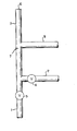
- the sole figure of the drawing is a schematic diagram of a cold gas generator in which the process of the invention can be carried out.
- An object of the invention is to provide a cold gas generating process resulting in a constant mass flow of cold gas at a constant temperature, which can be simply switched on or off in order to meet cold gas requirements.
- an improvement has been discovered in a process for the generation of a cold gas comprising introducing a relatively warm gas and a liquid cryogen into the upstream end of a mixing zone; permitting the gas and liquid cryogen to mix in the mixing zone, the amount of gas being sufficient to vaporize the liquid cryogen: and withdrawing the cold gas downstream in the mixing zone.
- the improvement comprises:
- Cold gas generation involves the mixing of a relatively warm gas with a liquid cryogen.
- the term "relatively warm” means that the gas is warmer than the liquid cryogen, but it may nevertheless be at a low temperature. Since the objective is to obtain a gas, the warm gas should be sufficient both in temperature and quantity to vaporize the liquid cryogen.
- both the gas and the cryogen are inert and they are preferably of the same chemical composition.
- the most commonly used gas and cryogen for this purpose is nitrogen, and both the gas and the liquid cryogen are obtained from conventional sources. While the temperature of the gas can range from just above the temperature of the liquid cryogen to ambient and above, ambient is the temperature of choice.
- mixing zone 7 is linear, i.e., the zone is constructed so that it conforms to a straight line.
- Pipe 3 provides this construction.
- the zone is dead-ended or capped as represented by dead end 6. This dead end serves to dampen pulsations in cold gas outlet 8 and the area between cold gas outlet 8 and dead end 6 provides adequate capacity to insure thorough mixing in mixing zone 7.
- the liquid cryogen liquid nitrogen in this case, is introduced at inlet pipe 2 by opening inlet valve 4.
- the flow rate of the liquid nitrogen is conventional, i.e., in the range of about one standard cubic foot per minute (scfm) to about 1000 scfm.
- the liquid cryogen and gas enter mixing zone 7 where the bulk of the liquid cryogen is vaporized and is mixed together with the gas. Some droplets of liquid cryogen remain, however, and these droplets proceed in a straight line along pipe 3 and against dead end 6 where they vaporize, expand, and are forced back into the cold gas mixture.
- a slipstream of cold gas is taken off pipe 3 at cold gas outlet pipe 8.
- This outlet pipe is preferably perpendicular to pipe 3, but can be situated at various angles to pipe 3. Although angles of 45 to 135 degrees or even greater can be used, the efficiency of the cold gas generation decreases with each degree of variation from the perpendicular.
- the interspatial placement of the various inlet and outlet pipes is not critical. however, and inlet pipes 1 and 2 can be at almost any angle to pipe 3 provided, of course, that both are feeding into the upstream end. It is not suggested, however, the the direction of flow of each inlet stream is such that the inlet gas opposes the inlet liquid as this would be counterproductive.
- the distance from the upstream end of mixing zone 7 to dead end 6 should be at least twice the distance from the upstream end to the point of withdrawal of the slipstream, and preferably at least four times the distance.
- the distance from the upstream end to dead end 6 will generally be at least four flow diameters and will usually be from ten to thirty flow diameters while the distance from the upstream end to the point of slipstream withdrawal will generally be at least one flow diameter and preferably at least three flow diameters.
- a "flow diameter” means the internal diameter of a pipe, in this case of pipe 3.
- a condensate drain can be added to the cold gas generator.
- the cold gas generator is insulated with the exception of valve activators.
- the materials from which the cold gas generator can be made are copper, brass, and AISI 300 series stainless steel or other alloys suitable for cryogenic temperature service.
- the flow rate of the liquid cryogen across valve 4 is proportional to P 3 minus P 2 : the inlet flow rate of the gas is constant; and the slipstream of cold gas is at a constant temperature with respect to time after transient cool down is completed.
- Pipe 1 and pipe 3 are 3/4 inch (nominal diameter) brass pipes and pipes 2 and 8 are 3/4 inch (internal diameter) copper tubing.
- Liquid nitrogen is supplied through pipe 2 from a conventional cylinder.
- Gaseous nitrogen is supplied through pipe 1, also from a conventional source.
- Temperatures are measured with a type "T" thermocouple having a digital "Omega" read out.
- Gas inlet pressure is measured prior to choking, which is accomplished by reducing the size of the orifice in valve 5 to a point at which the flow rate (velocity of the gas through the orifice) reaches Mach 1. This provides a constant mass flow at the upstream end of pipe 3.
- the number of flow diameters from the upstream end of pipe 3 to dead end 6 is 25.
- the number of flow diameters from the upstream end of pipe 3 to the beginning of pipe 8 is 12.
Landscapes
- Engineering & Computer Science (AREA)
- Mechanical Engineering (AREA)
- General Engineering & Computer Science (AREA)
- Filling Or Discharging Of Gas Storage Vessels (AREA)
- Separation By Low-Temperature Treatments (AREA)
Applications Claiming Priority (2)
| Application Number | Priority Date | Filing Date | Title |
|---|---|---|---|
| US568909 | 1984-01-06 | ||
| US06/568,909 US4481780A (en) | 1984-01-06 | 1984-01-06 | Process for the generation of a cold gas |
Publications (3)
| Publication Number | Publication Date |
|---|---|
| EP0148751A2 true EP0148751A2 (de) | 1985-07-17 |
| EP0148751A3 EP0148751A3 (en) | 1986-08-13 |
| EP0148751B1 EP0148751B1 (de) | 1990-03-14 |
Family
ID=24273255
Family Applications (1)
| Application Number | Title | Priority Date | Filing Date |
|---|---|---|---|
| EP85100102A Expired EP0148751B1 (de) | 1984-01-06 | 1985-01-07 | Kaltgaserzeugungsverfahren |
Country Status (7)
| Country | Link |
|---|---|
| US (1) | US4481780A (de) |
| EP (1) | EP0148751B1 (de) |
| BR (1) | BR8500046A (de) |
| CA (1) | CA1237062A (de) |
| DE (1) | DE3576465D1 (de) |
| ES (1) | ES539377A0 (de) |
| MX (1) | MX164974B (de) |
Families Citing this family (11)
| Publication number | Priority date | Publication date | Assignee | Title |
|---|---|---|---|---|
| US4607489A (en) * | 1985-05-21 | 1986-08-26 | Mg Industries | Method and apparatus for producing cold gas at a desired temperature |
| US4726195A (en) * | 1986-08-22 | 1988-02-23 | Air Products And Chemicals, Inc. | Cryogenic forced convection refrigerating system |
| GB9004640D0 (en) * | 1990-03-01 | 1990-04-25 | Boc Group Plc | Manufacture of glass articles |
| US5261243A (en) * | 1992-09-28 | 1993-11-16 | Lockheed Corporation | Supplemental cooling system for avionic equipment |
| US5394704A (en) * | 1993-11-04 | 1995-03-07 | The United States Of America As Represented By The Administrator Of The National Aeronautics And Space Administration | Alternate method for achieving temperature control in the -160 to +90 degrees Celcius range |
| FR2742851B1 (fr) * | 1995-12-26 | 1998-03-20 | Guillaume Gil | Perfectionnements aux procedes de fabrication de la neige artificielle, et dispositifs de mise en oeuvre |
| US5813237A (en) * | 1997-06-27 | 1998-09-29 | The Boc Group, Inc. | Cryogenic apparatus and method for spraying a cryogen incorporating generation of two phase flow |
| US6415628B1 (en) | 2001-07-25 | 2002-07-09 | Praxair Technology, Inc. | System for providing direct contact refrigeration |
| US8794013B2 (en) * | 2006-02-10 | 2014-08-05 | Praxair Technology, Inc. | Method and system for nucleation control in a controlled rate freezer (CRF) |
| ES2400410T3 (es) * | 2007-11-09 | 2013-04-09 | Praxair Technology, Inc. | Método y sistema para la congelación a velocidad controlada de material biológico |
| GB2565661B (en) * | 2016-03-14 | 2021-12-15 | Enermech Pty Ltd | A cooling system |
Family Cites Families (7)
| Publication number | Priority date | Publication date | Assignee | Title |
|---|---|---|---|---|
| NL205940A (de) * | ||||
| US3058317A (en) * | 1958-03-31 | 1962-10-16 | Superior Air Products Co | Vaporization of liquefied gases |
| US3106070A (en) * | 1960-10-07 | 1963-10-08 | British Oxygen Co Ltd | Cold gas supply system |
| FR2247667A1 (en) * | 1973-10-12 | 1975-05-09 | Black Sivalls & Bryson Inc | Combining LNG with fuel gas - by injecting LNG into heated gas in bypass circuit |
| DK48475A (da) * | 1975-02-10 | 1976-08-11 | Hoeyer As O G | Fremgangsmade ved blanding af en kontinuerligt strommende masse i veske-,creme eller pastaform med en gas samt anleg til udovelse af fremgangsmaden |
| US4237700A (en) * | 1979-04-20 | 1980-12-09 | Airco, Inc. | Methods and apparatus for providing refrigeration |
| US4343634A (en) * | 1981-03-23 | 1982-08-10 | Union Carbide Corporation | Process for operating a fluidized bed |
-
1984
- 1984-01-06 US US06/568,909 patent/US4481780A/en not_active Expired - Fee Related
-
1985
- 1985-01-04 CA CA000471540A patent/CA1237062A/en not_active Expired
- 1985-01-05 ES ES539377A patent/ES539377A0/es active Granted
- 1985-01-07 DE DE8585100102T patent/DE3576465D1/de not_active Expired - Lifetime
- 1985-01-07 BR BR8500046A patent/BR8500046A/pt not_active IP Right Cessation
- 1985-01-07 MX MX203976A patent/MX164974B/es unknown
- 1985-01-07 EP EP85100102A patent/EP0148751B1/de not_active Expired
Also Published As
| Publication number | Publication date |
|---|---|
| ES8602238A1 (es) | 1985-11-01 |
| ES539377A0 (es) | 1985-11-01 |
| EP0148751A3 (en) | 1986-08-13 |
| MX164974B (es) | 1992-10-09 |
| DE3576465D1 (de) | 1990-04-19 |
| EP0148751B1 (de) | 1990-03-14 |
| CA1237062A (en) | 1988-05-24 |
| BR8500046A (pt) | 1985-08-13 |
| US4481780A (en) | 1984-11-13 |
Similar Documents
| Publication | Publication Date | Title |
|---|---|---|
| EP0148751B1 (de) | Kaltgaserzeugungsverfahren | |
| US3689237A (en) | Fuel gas pipeline system | |
| US6513336B2 (en) | Apparatus and method for transferring a cryogenic fluid | |
| Fauske et al. | Source term considerations in connection with chemical accidents and vapour cloud modelling | |
| TW241331B (en) | Cryogenic rectification process and apparatus for vaporizing a pumped liquid product | |
| US2852922A (en) | Jet pump | |
| US5761911A (en) | System and method for controlled delivery of liquified gases | |
| JPS625268B2 (de) | ||
| KR880002620A (ko) | 고속기계 가공방법 및 장치 | |
| WO2023225476A3 (en) | System and method for cooling fluids containing hydrogen or helium | |
| US20100201006A1 (en) | Method and apparatus for stable and adjustable gas humidification | |
| US3742721A (en) | Method of regulation of the temperature of the liquefied gas or gaseous mixture in an apparatus for the liquefaction of gaseous fluids | |
| ES8305604A1 (es) | Un procedimiento para entregar un liquido criogeno a un punto de uso. | |
| US2548377A (en) | Means for producing liquid air rich in oxygen | |
| US5142875A (en) | Cooled pumping system | |
| GB1382727A (en) | Method and apparatus for cooling liquids | |
| US5195325A (en) | Liquid gas sampling | |
| GB861632A (en) | Method and apparatus for cooling a member such, for example, as a turbine blade of agas turbine engine | |
| US3960519A (en) | Method and system for generating a dehydrated inert gas stream | |
| FR2776760A1 (fr) | Procede et appareil de separation d'air par distillation cryogenique | |
| JPH10156160A (ja) | 液体酸素と液体窒素とをミキシングして混合物を作製するための方法および装置 | |
| Johnson | Quantitative study of the Hilsch heat separator | |
| US1961201A (en) | Process for separating mixed gases by liquefaction | |
| US1521385A (en) | Device for the production of compressed oxygen from liquid oxygen | |
| US3990265A (en) | Joule-Thomson liquifier utilizing the Leidenfrost principle |
Legal Events
| Date | Code | Title | Description |
|---|---|---|---|
| PUAI | Public reference made under article 153(3) epc to a published international application that has entered the european phase |
Free format text: ORIGINAL CODE: 0009012 |
|
| AK | Designated contracting states |
Designated state(s): BE DE FR IT LU NL |
|
| RIN1 | Information on inventor provided before grant (corrected) |
Inventor name: DELANO, MARK ANTHONY |
|
| PUAL | Search report despatched |
Free format text: ORIGINAL CODE: 0009013 |
|
| AK | Designated contracting states |
Kind code of ref document: A3 Designated state(s): BE DE FR IT LU NL |
|
| 17P | Request for examination filed |
Effective date: 19860828 |
|
| 17Q | First examination report despatched |
Effective date: 19880823 |
|
| ITF | It: translation for a ep patent filed | ||
| GRAA | (expected) grant |
Free format text: ORIGINAL CODE: 0009210 |
|
| AK | Designated contracting states |
Kind code of ref document: B1 Designated state(s): BE DE FR IT LU NL |
|
| PG25 | Lapsed in a contracting state [announced via postgrant information from national office to epo] |
Ref country code: NL Effective date: 19900314 |
|
| REF | Corresponds to: |
Ref document number: 3576465 Country of ref document: DE Date of ref document: 19900419 |
|
| ET | Fr: translation filed | ||
| NLV1 | Nl: lapsed or annulled due to failure to fulfill the requirements of art. 29p and 29m of the patents act | ||
| PLBE | No opposition filed within time limit |
Free format text: ORIGINAL CODE: 0009261 |
|
| STAA | Information on the status of an ep patent application or granted ep patent |
Free format text: STATUS: NO OPPOSITION FILED WITHIN TIME LIMIT |
|
| ITTA | It: last paid annual fee | ||
| PG25 | Lapsed in a contracting state [announced via postgrant information from national office to epo] |
Ref country code: LU Free format text: LAPSE BECAUSE OF NON-PAYMENT OF DUE FEES Effective date: 19910131 |
|
| 26N | No opposition filed | ||
| PGFP | Annual fee paid to national office [announced via postgrant information from national office to epo] |
Ref country code: DE Payment date: 19911204 Year of fee payment: 8 |
|
| PGFP | Annual fee paid to national office [announced via postgrant information from national office to epo] |
Ref country code: FR Payment date: 19911210 Year of fee payment: 8 |
|
| PGFP | Annual fee paid to national office [announced via postgrant information from national office to epo] |
Ref country code: BE Payment date: 19920127 Year of fee payment: 8 |
|
| PG25 | Lapsed in a contracting state [announced via postgrant information from national office to epo] |
Ref country code: BE Effective date: 19930131 |
|
| BERE | Be: lapsed |
Owner name: UNION CARBIDE CORP. Effective date: 19930131 |
|
| PG25 | Lapsed in a contracting state [announced via postgrant information from national office to epo] |
Ref country code: FR Effective date: 19930930 |
|
| PG25 | Lapsed in a contracting state [announced via postgrant information from national office to epo] |
Ref country code: DE Effective date: 19931001 |
|
| REG | Reference to a national code |
Ref country code: FR Ref legal event code: ST |