EP0148804A1 - Balkenofen zur schnellen kontinuierlichen oder diskontinuierlichen Erwärmung von keramischen Produkten - Google Patents
Balkenofen zur schnellen kontinuierlichen oder diskontinuierlichen Erwärmung von keramischen Produkten Download PDFInfo
- Publication number
- EP0148804A1 EP0148804A1 EP85400038A EP85400038A EP0148804A1 EP 0148804 A1 EP0148804 A1 EP 0148804A1 EP 85400038 A EP85400038 A EP 85400038A EP 85400038 A EP85400038 A EP 85400038A EP 0148804 A1 EP0148804 A1 EP 0148804A1
- Authority
- EP
- European Patent Office
- Prior art keywords
- bars
- oven
- bar
- oven according
- products
- Prior art date
- Legal status (The legal status is an assumption and is not a legal conclusion. Google has not performed a legal analysis and makes no representation as to the accuracy of the status listed.)
- Granted
Links
Images



Classifications
-
- F—MECHANICAL ENGINEERING; LIGHTING; HEATING; WEAPONS; BLASTING
- F27—FURNACES; KILNS; OVENS; RETORTS
- F27B—FURNACES, KILNS, OVENS OR RETORTS IN GENERAL; OPEN SINTERING OR LIKE APPARATUS
- F27B9/00—Furnaces through which the charge is moved mechanically, e.g. of tunnel type; Similar furnaces in which the charge moves by gravity
- F27B9/14—Furnaces through which the charge is moved mechanically, e.g. of tunnel type; Similar furnaces in which the charge moves by gravity characterised by the path of the charge during treatment; characterised by the means by which the charge is moved during treatment
- F27B9/20—Furnaces through which the charge is moved mechanically, e.g. of tunnel type; Similar furnaces in which the charge moves by gravity characterised by the path of the charge during treatment; characterised by the means by which the charge is moved during treatment the charge moving in a substantially straight path
- F27B9/24—Furnaces through which the charge is moved mechanically, e.g. of tunnel type; Similar furnaces in which the charge moves by gravity characterised by the path of the charge during treatment; characterised by the means by which the charge is moved during treatment the charge moving in a substantially straight path being carried by a conveyor
-
- F—MECHANICAL ENGINEERING; LIGHTING; HEATING; WEAPONS; BLASTING
- F27—FURNACES; KILNS; OVENS; RETORTS
- F27B—FURNACES, KILNS, OVENS OR RETORTS IN GENERAL; OPEN SINTERING OR LIKE APPARATUS
- F27B9/00—Furnaces through which the charge is moved mechanically, e.g. of tunnel type; Similar furnaces in which the charge moves by gravity
- F27B9/06—Furnaces through which the charge is moved mechanically, e.g. of tunnel type; Similar furnaces in which the charge moves by gravity heated without contact between combustion gases and charge; electrically heated
- F27B9/08—Furnaces through which the charge is moved mechanically, e.g. of tunnel type; Similar furnaces in which the charge moves by gravity heated without contact between combustion gases and charge; electrically heated heated through chamber walls
-
- F—MECHANICAL ENGINEERING; LIGHTING; HEATING; WEAPONS; BLASTING
- F27—FURNACES; KILNS; OVENS; RETORTS
- F27B—FURNACES, KILNS, OVENS OR RETORTS IN GENERAL; OPEN SINTERING OR LIKE APPARATUS
- F27B9/00—Furnaces through which the charge is moved mechanically, e.g. of tunnel type; Similar furnaces in which the charge moves by gravity
- F27B9/14—Furnaces through which the charge is moved mechanically, e.g. of tunnel type; Similar furnaces in which the charge moves by gravity characterised by the path of the charge during treatment; characterised by the means by which the charge is moved during treatment
- F27B9/20—Furnaces through which the charge is moved mechanically, e.g. of tunnel type; Similar furnaces in which the charge moves by gravity characterised by the path of the charge during treatment; characterised by the means by which the charge is moved during treatment the charge moving in a substantially straight path
- F27B9/24—Furnaces through which the charge is moved mechanically, e.g. of tunnel type; Similar furnaces in which the charge moves by gravity characterised by the path of the charge during treatment; characterised by the means by which the charge is moved during treatment the charge moving in a substantially straight path being carried by a conveyor
- F27B9/2407—Furnaces through which the charge is moved mechanically, e.g. of tunnel type; Similar furnaces in which the charge moves by gravity characterised by the path of the charge during treatment; characterised by the means by which the charge is moved during treatment the charge moving in a substantially straight path being carried by a conveyor the conveyor being constituted by rollers (roller hearth furnace)
-
- F—MECHANICAL ENGINEERING; LIGHTING; HEATING; WEAPONS; BLASTING
- F27—FURNACES; KILNS; OVENS; RETORTS
- F27B—FURNACES, KILNS, OVENS OR RETORTS IN GENERAL; OPEN SINTERING OR LIKE APPARATUS
- F27B9/00—Furnaces through which the charge is moved mechanically, e.g. of tunnel type; Similar furnaces in which the charge moves by gravity
- F27B9/14—Furnaces through which the charge is moved mechanically, e.g. of tunnel type; Similar furnaces in which the charge moves by gravity characterised by the path of the charge during treatment; characterised by the means by which the charge is moved during treatment
- F27B9/20—Furnaces through which the charge is moved mechanically, e.g. of tunnel type; Similar furnaces in which the charge moves by gravity characterised by the path of the charge during treatment; characterised by the means by which the charge is moved during treatment the charge moving in a substantially straight path
- F27B9/26—Furnaces through which the charge is moved mechanically, e.g. of tunnel type; Similar furnaces in which the charge moves by gravity characterised by the path of the charge during treatment; characterised by the means by which the charge is moved during treatment the charge moving in a substantially straight path on or in trucks, sleds, or containers
-
- F—MECHANICAL ENGINEERING; LIGHTING; HEATING; WEAPONS; BLASTING
- F27—FURNACES; KILNS; OVENS; RETORTS
- F27B—FURNACES, KILNS, OVENS OR RETORTS IN GENERAL; OPEN SINTERING OR LIKE APPARATUS
- F27B9/00—Furnaces through which the charge is moved mechanically, e.g. of tunnel type; Similar furnaces in which the charge moves by gravity
- F27B9/30—Details, accessories or equipment specially adapted for furnaces of these types
- F27B9/32—Casings
-
- F—MECHANICAL ENGINEERING; LIGHTING; HEATING; WEAPONS; BLASTING
- F27—FURNACES; KILNS; OVENS; RETORTS
- F27B—FURNACES, KILNS, OVENS OR RETORTS IN GENERAL; OPEN SINTERING OR LIKE APPARATUS
- F27B9/00—Furnaces through which the charge is moved mechanically, e.g. of tunnel type; Similar furnaces in which the charge moves by gravity
- F27B9/12—Furnaces through which the charge is moved mechanically, e.g. of tunnel type; Similar furnaces in which the charge moves by gravity with special arrangements for preheating or cooling the charge
- F27B2009/124—Cooling
-
- F—MECHANICAL ENGINEERING; LIGHTING; HEATING; WEAPONS; BLASTING
- F27—FURNACES; KILNS; OVENS; RETORTS
- F27B—FURNACES, KILNS, OVENS OR RETORTS IN GENERAL; OPEN SINTERING OR LIKE APPARATUS
- F27B9/00—Furnaces through which the charge is moved mechanically, e.g. of tunnel type; Similar furnaces in which the charge moves by gravity
- F27B9/30—Details, accessories or equipment specially adapted for furnaces of these types
- F27B9/36—Arrangements of heating devices
- F27B2009/3623—Heaters located under the track
-
- F—MECHANICAL ENGINEERING; LIGHTING; HEATING; WEAPONS; BLASTING
- F27—FURNACES; KILNS; OVENS; RETORTS
- F27B—FURNACES, KILNS, OVENS OR RETORTS IN GENERAL; OPEN SINTERING OR LIKE APPARATUS
- F27B9/00—Furnaces through which the charge is moved mechanically, e.g. of tunnel type; Similar furnaces in which the charge moves by gravity
- F27B9/30—Details, accessories or equipment specially adapted for furnaces of these types
- F27B9/36—Arrangements of heating devices
- F27B2009/3646—Heating the ceiling or the walls for a reverberatory effect
-
- F—MECHANICAL ENGINEERING; LIGHTING; HEATING; WEAPONS; BLASTING
- F27—FURNACES; KILNS; OVENS; RETORTS
- F27B—FURNACES, KILNS, OVENS OR RETORTS IN GENERAL; OPEN SINTERING OR LIKE APPARATUS
- F27B9/00—Furnaces through which the charge is moved mechanically, e.g. of tunnel type; Similar furnaces in which the charge moves by gravity
- F27B9/02—Furnaces through which the charge is moved mechanically, e.g. of tunnel type; Similar furnaces in which the charge moves by gravity of multiple-track type; of multiple-chamber type; Combinations of furnaces
- F27B9/029—Multicellular type furnaces constructed with add-on modules
-
- F—MECHANICAL ENGINEERING; LIGHTING; HEATING; WEAPONS; BLASTING
- F27—FURNACES; KILNS; OVENS; RETORTS
- F27B—FURNACES, KILNS, OVENS OR RETORTS IN GENERAL; OPEN SINTERING OR LIKE APPARATUS
- F27B9/00—Furnaces through which the charge is moved mechanically, e.g. of tunnel type; Similar furnaces in which the charge moves by gravity
- F27B9/06—Furnaces through which the charge is moved mechanically, e.g. of tunnel type; Similar furnaces in which the charge moves by gravity heated without contact between combustion gases and charge; electrically heated
- F27B9/08—Furnaces through which the charge is moved mechanically, e.g. of tunnel type; Similar furnaces in which the charge moves by gravity heated without contact between combustion gases and charge; electrically heated heated through chamber walls
- F27B9/082—Muffle furnaces
-
- F—MECHANICAL ENGINEERING; LIGHTING; HEATING; WEAPONS; BLASTING
- F27—FURNACES; KILNS; OVENS; RETORTS
- F27B—FURNACES, KILNS, OVENS OR RETORTS IN GENERAL; OPEN SINTERING OR LIKE APPARATUS
- F27B9/00—Furnaces through which the charge is moved mechanically, e.g. of tunnel type; Similar furnaces in which the charge moves by gravity
- F27B9/14—Furnaces through which the charge is moved mechanically, e.g. of tunnel type; Similar furnaces in which the charge moves by gravity characterised by the path of the charge during treatment; characterised by the means by which the charge is moved during treatment
- F27B9/20—Furnaces through which the charge is moved mechanically, e.g. of tunnel type; Similar furnaces in which the charge moves by gravity characterised by the path of the charge during treatment; characterised by the means by which the charge is moved during treatment the charge moving in a substantially straight path
- F27B9/24—Furnaces through which the charge is moved mechanically, e.g. of tunnel type; Similar furnaces in which the charge moves by gravity characterised by the path of the charge during treatment; characterised by the means by which the charge is moved during treatment the charge moving in a substantially straight path being carried by a conveyor
- F27B9/2469—Furnaces through which the charge is moved mechanically, e.g. of tunnel type; Similar furnaces in which the charge moves by gravity characterised by the path of the charge during treatment; characterised by the means by which the charge is moved during treatment the charge moving in a substantially straight path being carried by a conveyor the conveyor being constituted by rollable bodies
-
- F—MECHANICAL ENGINEERING; LIGHTING; HEATING; WEAPONS; BLASTING
- F27—FURNACES; KILNS; OVENS; RETORTS
- F27B—FURNACES, KILNS, OVENS OR RETORTS IN GENERAL; OPEN SINTERING OR LIKE APPARATUS
- F27B9/00—Furnaces through which the charge is moved mechanically, e.g. of tunnel type; Similar furnaces in which the charge moves by gravity
- F27B9/14—Furnaces through which the charge is moved mechanically, e.g. of tunnel type; Similar furnaces in which the charge moves by gravity characterised by the path of the charge during treatment; characterised by the means by which the charge is moved during treatment
- F27B9/20—Furnaces through which the charge is moved mechanically, e.g. of tunnel type; Similar furnaces in which the charge moves by gravity characterised by the path of the charge during treatment; characterised by the means by which the charge is moved during treatment the charge moving in a substantially straight path
- F27B9/26—Furnaces through which the charge is moved mechanically, e.g. of tunnel type; Similar furnaces in which the charge moves by gravity characterised by the path of the charge during treatment; characterised by the means by which the charge is moved during treatment the charge moving in a substantially straight path on or in trucks, sleds, or containers
- F27B9/262—Furnaces through which the charge is moved mechanically, e.g. of tunnel type; Similar furnaces in which the charge moves by gravity characterised by the path of the charge during treatment; characterised by the means by which the charge is moved during treatment the charge moving in a substantially straight path on or in trucks, sleds, or containers on or in trucks
-
- Y—GENERAL TAGGING OF NEW TECHNOLOGICAL DEVELOPMENTS; GENERAL TAGGING OF CROSS-SECTIONAL TECHNOLOGIES SPANNING OVER SEVERAL SECTIONS OF THE IPC; TECHNICAL SUBJECTS COVERED BY FORMER USPC CROSS-REFERENCE ART COLLECTIONS [XRACs] AND DIGESTS
- Y02—TECHNOLOGIES OR APPLICATIONS FOR MITIGATION OR ADAPTATION AGAINST CLIMATE CHANGE
- Y02P—CLIMATE CHANGE MITIGATION TECHNOLOGIES IN THE PRODUCTION OR PROCESSING OF GOODS
- Y02P40/00—Technologies relating to the processing of minerals
- Y02P40/60—Production of ceramic materials or ceramic elements, e.g. substitution of clay or shale by alternative raw materials, e.g. ashes
Definitions
- the invention is in the field of pass-through and intermittent ovens. It relates more specifically to a tunnel pass-through oven with bars for rapid continuous or intermittent firing of ceramic products.
- An object of the invention is to provide a rod oven, which eliminates the drawbacks of a train of conventional wagons lined with. refractory.
- Another object of the invention is to provide a rod oven, the hearth of which becomes fixed and an integral part of the oven, which means that the mass carried is reduced to a minimum.
- Yet another object of the present invention is to produce a bar oven of new design, the loads of which are to be cooked are weighed directly on a succession of horizontal transverse bars, which pass through the oven from side to side with or without intermediate support, these bars being spaced apart and resting at their ends on movable beams which move between the fixed upper and lower parts of the furnace.
- the present invention therefore relates to a passage tunnel oven, comprising a certain number of bars for the rapid cooking of industrial products, in particular ceramic products, this oven comprising a structure with cut legs, consisting of a fixed hearth and d 'a vault and connected by a discontinuous bracing system, and a mobile carrying train constituted by longitudinal members to which are associated carrying bars intended to receive the products to be cooked, and extending transversely in the oven from side to side with or without support intermediate.
- the bracing system between the upper part of the oven or vault and the lower part or bottom consists of mechanical jacks spaced from each other.
- the side members advantageously consist of a lateral metal framework enveloping the refractory fiber, and mounted on rollers cooperating with a system of guide rails.
- the support bars are made of ceramic material, refractory material or metal, they can rest directly or be fixed on the side members.
- the carrier bars are optionally associated with either a system of auxiliary bars arranged in line with the said carrier bars, or else thin perforated plates of ceramic material placed in suitable locations on the said carrier bars.
- e, n preheats whether they are “muffled”, “semi-muffle” ovens, in free flame, electric or bi-energy, the combustion products and the injections d 'hot air from rapid cooling is channeled under the entire surface of the hearth, which thus radiates under the products in the manner of a hot plate under a container.
- the reverse cooling system possible according to the present invention and constituted by upper blows and resumptions of hot air at the bottom greatly improves the homogeneity and therefore the cooling efficiency, all the more so since it is no longer necessary to provide refractory wagon infrastructure.
- the rod oven has the same cooperation of means of transverse bars mounted on side rails and of structure with cut corners according to the present invention.
- its general shape is that of a hose cut horizontally in 2 at the plane of the load-bearing bars, while its section and its heating equipment are identical over its entire length, which makes it possible to produce it in a modular oven of corresponding length. as needed by the user.
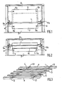
- the bar tunnel oven consists of carrier bars 1,. an upper static part 2 and a lower static part 3.
- the supporting bars 1 are associated with lateral beams 4 forming part of a movable train supporting the bars which will be described in more detail below.
- the upper static part 2 includes an upper heating zone 5 provided with side burners 6a, 6b while the dashed line indicates the limit of a high load gauge.
- the lower static part 3 comprises a lower heating zone 7 provided with two series of lateral burners Sa, 8b. In these two figures, the lateral structures of cut corners 9a, 9b according to the invention are clearly visible.
- the bar tunnel oven is an oven also made up of three separate independent parts, as in FIG.
- the movable bar support train shown in Figure 3 consists of two side rails 4 on which rests or is fixed a number of horizontal transverse bars the oven from side to side.
- the longitudinal members 4 are associated with rollers 12 according to an arrangement which will be described in more detail below.
- auxiliary bars 13 rests on the support bars 1 parallel to the side members 4.
- These auxiliary bars can optionally be replaced by perforated or non-thin plates and placed on the support bars. .
- FIG. 4 1a load-bearing bar 1, made of ceramic material, rests at its ends on a respective spar 4a, by means of a cordierite junction piece 14 which rests on the profile 4a of the spar on the face lateral of which is mounted a roller 12 resting on a rail 15 secured to a support profile 16.
- An upper guide profile 17 is also provided for the spar assembly 4a.
- FIG. 5 which is a partial section between support bars, shows in more detail the insulator 4b made of compact refractory fibers of the spar 4 with its lateral profile 4a on which is pivotally mounted a support roller 12 resting on its rail 15.
- FIG. 6 represents a particular embodiment of carrier bars 1, in particular intended for baking ovens for flat element of the tile type.
- This load-bearing bar l made of steel profile, is wrapped in a refractory lining traversed by support elements lc integral with the bar 1 and comprising at their free ends a rounded refractory structure Id intended to receive two flat elements of the tile type shown in dashed lines on. Also shown in this figure are arrangements of seals 18, 19 for the upper 2 and lower 3 static areas, respectively.
- FIG. 7 is shown the cooking zone, a bar tunnel oven according to the invention, comprising a heating system with upper and lower radiant muffles.
- This oven comprises, according to the invention, an upper static part or arch 2 shaped as an upper radiant muffle 20 associated with a series of burners 21, and a lower static part or bottom 3 shaped to present a lower radiant muffle 22 associated with several series side burners, one of which 23 is shown in the drawing.
- Each bar 1 passes through the oven from side to side by coming to bear at its ends on the longitudinal beams 4 which move by means of the rollers 12 resting on the guide support structure 15, 16.
- the zones of cut corners 9a, 9b, of the oven appear clearly, as well as the spacer structure with spaced cylinders 24a, 24b, respectively.
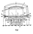
- FIG. 8 represents a section of a tunnel oven of the invention, at its cooling zone, of structure particularly suitable for rapid cooling of the cooking products, the structure of cut piers 9a, 9b, cooperating with the train mobile support for carrying bars 1, 4.12 which is identical to that shown in FIG. 7 and described above in more detail.
- cold air blows 25 are provided at the top of the oven and at the hot air return arrangement below the carrier bars 1.
- the hot air return is made according to the invention through perforated plates 26 by which the air from the upper zone 2 communicates according to the arrows fl, f2, f3 with a lower compartment 27 with which is associated two lateral adjustment devices 28a, 28b.
- Such an inverted cooling system consists of an upper cold air blast 25 and a lower hot air return device 26, 27, at the bottom greatly improves the homogeneity and therefore the efficiency of the cooling, this result, being the consequence of the particular structure of furnace sidewalls cut s according to the invention.
- FIG. 9 comprising a slow cooling zone
- the structures of bars 1-beams 4-supporting roller 12 and of cut pedestal structure 9a, 9b are identical to those described in the embodiments of Figures 7 and 8.
- a refractory structure underlying the bars 29 1. This form of oven is particularly applicable to large pieces, as shown in dashed lines in FIG. 9.
- FIG. 10 two preheating zones of a rapid-cooling oven, as shown in FIG. 8, are shown, the hot rapid-cooling air of which is injected by series of side nozzles at the level of the vault 2, one of which 30 is shown with the drawing.
- the structure of load-bearing bars and cut corners is identical to that shown in FIGS. 7 to 9.
- a refractory structure 31 is provided, which is subjacent to the bars 1 and provides a space between the latter for the passage of the muffle fumes.
- the materials that are used for the manufacture of tunnel tunnel ovens according to the invention are those usually used in the manufacture of conventional type ovens. However, at the level of the bars, the latter consist of a hollow profile of a mechanical nature and characteristic.
- these bars will be simple ordinary steel profiles (with or without lining) or refractory steel for low temperatures and very fast cycle; they will be made of ceramic materials with a high alumina content or based on silicon carbide for higher temperatures.
- These support bars are integral with the metal frame of the side members. They can simply be placed on suitable ceramic supports when they are made of ceramic or refractory materials. In all cases, the side members will receive an insulating lining which restores the insulation to the right of the cut of the sides. The oven will be sealed at this level either by conventional sand joints or by waterproof boxes.
- the load-bearing elements move by sliding in the manner of sliding pads or by rolling on a sheet of balls or rollers.
- a tunnel oven is produced which makes it possible to overcome conventional wagons which consume a great deal of energy, and which makes it possible to install their location which has become free.
- products to be cooked thanks to a combination of a movable support train of spaced bars with a structure of a cross-section oven.
- This new oven design notably applicable to ovens at high temperature, that is to say above 1000 ° C., allows a considerable energy saving, since it is no longer necessary to heat the wagons,
- this type of oven applies to the continuous or intermittent firing of different ceramic and other products, without the need to provide infrastructure of wagons passing through the oven, which allows installation at their place of efficient thermal equipment as described above.
- the invention also extends, as new industrial products, to passage tunnel ovens comprising a structure with cut legs.
Landscapes
- Engineering & Computer Science (AREA)
- Mechanical Engineering (AREA)
- General Engineering & Computer Science (AREA)
- Chemical & Material Sciences (AREA)
- Combustion & Propulsion (AREA)
- Tunnel Furnaces (AREA)
- Compositions Of Oxide Ceramics (AREA)
- Cookers (AREA)
- Ceramic Products (AREA)
- General Preparation And Processing Of Foods (AREA)
Priority Applications (1)
| Application Number | Priority Date | Filing Date | Title |
|---|---|---|---|
| AT85400038T ATE30766T1 (de) | 1984-01-10 | 1985-01-09 | Balkenofen zur schnellen kontinuierlichen oder diskontinuierlichen erwaermung von keramischen produkten. |
Applications Claiming Priority (2)
| Application Number | Priority Date | Filing Date | Title |
|---|---|---|---|
| FR8400312A FR2557965B1 (fr) | 1984-01-10 | 1984-01-10 | Four a barres pour cuisson rapide en continu ou en intermittent des produits ceramiques |
| FR8400312 | 1984-01-10 |
Publications (2)
| Publication Number | Publication Date |
|---|---|
| EP0148804A1 true EP0148804A1 (de) | 1985-07-17 |
| EP0148804B1 EP0148804B1 (de) | 1987-11-11 |
Family
ID=9299983
Family Applications (1)
| Application Number | Title | Priority Date | Filing Date |
|---|---|---|---|
| EP85400038A Expired EP0148804B1 (de) | 1984-01-10 | 1985-01-09 | Balkenofen zur schnellen kontinuierlichen oder diskontinuierlichen Erwärmung von keramischen Produkten |
Country Status (5)
| Country | Link |
|---|---|
| EP (1) | EP0148804B1 (de) |
| AT (1) | ATE30766T1 (de) |
| DE (1) | DE3560962D1 (de) |
| ES (1) | ES8606622A1 (de) |
| FR (1) | FR2557965B1 (de) |
Cited By (4)
| Publication number | Priority date | Publication date | Assignee | Title |
|---|---|---|---|---|
| FR2664032A1 (fr) * | 1990-06-27 | 1992-01-03 | Riedhammer Gmbh Co Kg | Four a rouleaux. |
| WO1992004588A1 (en) * | 1990-09-03 | 1992-03-19 | Mori S.P.A. | Kiln with displaceable frames for the firing of manufactured articles |
| EP0531859A1 (de) * | 1991-09-13 | 1993-03-17 | Karl-Heinz Brakemeier | Brennofen insb. für keramische Erzeugnisse |
| CN104818497A (zh) * | 2015-04-17 | 2015-08-05 | 郑州经纬科技实业有限公司 | 电解铝用阴极炭块预热装置及其使用方法 |
Citations (5)
| Publication number | Priority date | Publication date | Assignee | Title |
|---|---|---|---|---|
| FR893570A (fr) * | 1943-01-08 | 1944-08-04 | Four de traitement thermique | |
| FR2323647A1 (fr) * | 1975-09-15 | 1977-04-08 | Mcmaster Harold | Four et installation de trempe de verre a mouvement alternatif |
| DE3031474A1 (de) * | 1980-08-21 | 1982-02-25 | Keller Ofenbau GmbH, 4530 Ibbenbüren | Transportbahn in einem tunnelofen zum brennen von keramischem gut |
| US4338078A (en) * | 1980-11-24 | 1982-07-06 | Photon Power, Inc. | Heated conveyor system |
| EP0086693A1 (de) * | 1982-02-12 | 1983-08-24 | ENTREPRISE HARTMANN PERE & FILS | Dichtungseinrichtung für einen Tunnelofen, Wagen und Tunnelofen für diese Dichtungseinrichtung |
-
1984
- 1984-01-10 FR FR8400312A patent/FR2557965B1/fr not_active Expired
-
1985
- 1985-01-09 ES ES539418A patent/ES8606622A1/es not_active Expired
- 1985-01-09 EP EP85400038A patent/EP0148804B1/de not_active Expired
- 1985-01-09 AT AT85400038T patent/ATE30766T1/de not_active IP Right Cessation
- 1985-01-09 DE DE8585400038T patent/DE3560962D1/de not_active Expired
Patent Citations (5)
| Publication number | Priority date | Publication date | Assignee | Title |
|---|---|---|---|---|
| FR893570A (fr) * | 1943-01-08 | 1944-08-04 | Four de traitement thermique | |
| FR2323647A1 (fr) * | 1975-09-15 | 1977-04-08 | Mcmaster Harold | Four et installation de trempe de verre a mouvement alternatif |
| DE3031474A1 (de) * | 1980-08-21 | 1982-02-25 | Keller Ofenbau GmbH, 4530 Ibbenbüren | Transportbahn in einem tunnelofen zum brennen von keramischem gut |
| US4338078A (en) * | 1980-11-24 | 1982-07-06 | Photon Power, Inc. | Heated conveyor system |
| EP0086693A1 (de) * | 1982-02-12 | 1983-08-24 | ENTREPRISE HARTMANN PERE & FILS | Dichtungseinrichtung für einen Tunnelofen, Wagen und Tunnelofen für diese Dichtungseinrichtung |
Cited By (6)
| Publication number | Priority date | Publication date | Assignee | Title |
|---|---|---|---|---|
| FR2664032A1 (fr) * | 1990-06-27 | 1992-01-03 | Riedhammer Gmbh Co Kg | Four a rouleaux. |
| WO1992004588A1 (en) * | 1990-09-03 | 1992-03-19 | Mori S.P.A. | Kiln with displaceable frames for the firing of manufactured articles |
| US5605455A (en) * | 1990-09-03 | 1997-02-25 | Mori S.P.A. | Kiln with displaceable frames for the firing of manufactured articles |
| EP0531859A1 (de) * | 1991-09-13 | 1993-03-17 | Karl-Heinz Brakemeier | Brennofen insb. für keramische Erzeugnisse |
| CN104818497A (zh) * | 2015-04-17 | 2015-08-05 | 郑州经纬科技实业有限公司 | 电解铝用阴极炭块预热装置及其使用方法 |
| CN104818497B (zh) * | 2015-04-17 | 2017-05-10 | 郑州经纬科技实业有限公司 | 电解铝用阴极炭块预热装置及其使用方法 |
Also Published As
| Publication number | Publication date |
|---|---|
| ES539418A0 (es) | 1986-04-01 |
| ES8606622A1 (es) | 1986-04-01 |
| DE3560962D1 (en) | 1987-12-17 |
| FR2557965A1 (fr) | 1985-07-12 |
| FR2557965B1 (fr) | 1988-07-01 |
| ATE30766T1 (de) | 1987-11-15 |
| EP0148804B1 (de) | 1987-11-11 |
Similar Documents
| Publication | Publication Date | Title |
|---|---|---|
| EP0148804B1 (de) | Balkenofen zur schnellen kontinuierlichen oder diskontinuierlichen Erwärmung von keramischen Produkten | |
| CN110425871A (zh) | 推板炉的炉壁结构 | |
| GB2432570A (en) | Loading bricks onto a kiln car using a fork | |
| US4348175A (en) | Kiln car | |
| US4330267A (en) | Kiln car | |
| US8087931B2 (en) | Device for supporting articles to be fired that has a defined compensation of thermal expansions | |
| CA1218844A (fr) | Fours a longerons refractaires | |
| FR2488277A1 (fr) | Four pour le chauffage de metal et en particulier de profiles intermediaires avant leur laminage | |
| US2985440A (en) | Pallet construction for sintering apparatus | |
| JP3148438B2 (ja) | ビームキルン | |
| EP0048645A1 (de) | Elektrisch beheizter Ofen mit geringer thermischer Trägheit | |
| JPH08327252A (ja) | 焼成炉用台車 | |
| EP0035865B1 (de) | Vertikalschachtofen mit Transportvorrichtungen für brennendes Gut | |
| FR2610710A1 (fr) | Four de cuisson de produits a base d'argile ou similaire | |
| EP2898275B1 (de) | Hochtemperaturbrennofen | |
| JP3148439B2 (ja) | ビームキルン | |
| FR2664032A1 (fr) | Four a rouleaux. | |
| JPH0642877A (ja) | ビームキルン | |
| FR2866418A1 (fr) | Dispositif de transport de produits dans une enceinte chaude | |
| FR2649785A1 (fr) | Support pour materiel a cuire en ceramique | |
| EP0219482B1 (de) | Haubenofen | |
| BE468198A (de) | ||
| JP3148440B2 (ja) | ビームキルン | |
| FR2458775A1 (fr) | Revetement pour des tubes situes dans des espaces de chauffe de fours industriels | |
| FR2761146A1 (fr) | Four pour la cuisson d'articles en terre cuite |
Legal Events
| Date | Code | Title | Description |
|---|---|---|---|
| PUAI | Public reference made under article 153(3) epc to a published international application that has entered the european phase |
Free format text: ORIGINAL CODE: 0009012 |
|
| AK | Designated contracting states |
Designated state(s): AT BE CH DE GB IT LI LU NL SE |
|
| 17P | Request for examination filed |
Effective date: 19851119 |
|
| 17Q | First examination report despatched |
Effective date: 19870128 |
|
| GRAA | (expected) grant |
Free format text: ORIGINAL CODE: 0009210 |
|
| AK | Designated contracting states |
Kind code of ref document: B1 Designated state(s): AT BE CH DE GB IT LI LU NL SE |
|
| PG25 | Lapsed in a contracting state [announced via postgrant information from national office to epo] |
Ref country code: AT Effective date: 19871111 |
|
| REF | Corresponds to: |
Ref document number: 30766 Country of ref document: AT Date of ref document: 19871115 Kind code of ref document: T |
|
| PG25 | Lapsed in a contracting state [announced via postgrant information from national office to epo] |
Ref country code: SE Effective date: 19871130 |
|
| REF | Corresponds to: |
Ref document number: 3560962 Country of ref document: DE Date of ref document: 19871217 |
|
| ITF | It: translation for a ep patent filed | ||
| GBT | Gb: translation of ep patent filed (gb section 77(6)(a)/1977) | ||
| PLBE | No opposition filed within time limit |
Free format text: ORIGINAL CODE: 0009261 |
|
| STAA | Information on the status of an ep patent application or granted ep patent |
Free format text: STATUS: NO OPPOSITION FILED WITHIN TIME LIMIT |
|
| 26N | No opposition filed | ||
| ITTA | It: last paid annual fee | ||
| EPTA | Lu: last paid annual fee | ||
| PGFP | Annual fee paid to national office [announced via postgrant information from national office to epo] |
Ref country code: GB Payment date: 19971231 Year of fee payment: 14 |
|
| PGFP | Annual fee paid to national office [announced via postgrant information from national office to epo] |
Ref country code: LU Payment date: 19980106 Year of fee payment: 14 |
|
| PGFP | Annual fee paid to national office [announced via postgrant information from national office to epo] |
Ref country code: NL Payment date: 19980130 Year of fee payment: 14 |
|
| PGFP | Annual fee paid to national office [announced via postgrant information from national office to epo] |
Ref country code: CH Payment date: 19980421 Year of fee payment: 14 |
|
| PG25 | Lapsed in a contracting state [announced via postgrant information from national office to epo] |
Ref country code: LU Free format text: LAPSE BECAUSE OF NON-PAYMENT OF DUE FEES Effective date: 19990109 Ref country code: GB Free format text: LAPSE BECAUSE OF NON-PAYMENT OF DUE FEES Effective date: 19990109 |
|
| PG25 | Lapsed in a contracting state [announced via postgrant information from national office to epo] |
Ref country code: LI Free format text: LAPSE BECAUSE OF NON-PAYMENT OF DUE FEES Effective date: 19990131 Ref country code: CH Free format text: LAPSE BECAUSE OF NON-PAYMENT OF DUE FEES Effective date: 19990131 |
|
| PGFP | Annual fee paid to national office [announced via postgrant information from national office to epo] |
Ref country code: BE Payment date: 19990212 Year of fee payment: 15 |
|
| PGFP | Annual fee paid to national office [announced via postgrant information from national office to epo] |
Ref country code: DE Payment date: 19990223 Year of fee payment: 15 |
|
| PG25 | Lapsed in a contracting state [announced via postgrant information from national office to epo] |
Ref country code: NL Free format text: LAPSE BECAUSE OF NON-PAYMENT OF DUE FEES Effective date: 19990801 |
|
| GBPC | Gb: european patent ceased through non-payment of renewal fee |
Effective date: 19990109 |
|
| REG | Reference to a national code |
Ref country code: CH Ref legal event code: PL |
|
| PG25 | Lapsed in a contracting state [announced via postgrant information from national office to epo] |
Ref country code: BE Free format text: LAPSE BECAUSE OF NON-PAYMENT OF DUE FEES Effective date: 20000131 |
|
| BERE | Be: lapsed |
Owner name: OCCIDENTAL INDUSTRIES Effective date: 20000131 |
|
| PG25 | Lapsed in a contracting state [announced via postgrant information from national office to epo] |
Ref country code: DE Free format text: LAPSE BECAUSE OF NON-PAYMENT OF DUE FEES Effective date: 20001101 |