EP0148807A1 - Schutz für Rohrgewinde und Rohrverbindungskontaktflächen - Google Patents
Schutz für Rohrgewinde und Rohrverbindungskontaktflächen Download PDFInfo
- Publication number
- EP0148807A1 EP0148807A1 EP85420003A EP85420003A EP0148807A1 EP 0148807 A1 EP0148807 A1 EP 0148807A1 EP 85420003 A EP85420003 A EP 85420003A EP 85420003 A EP85420003 A EP 85420003A EP 0148807 A1 EP0148807 A1 EP 0148807A1
- Authority
- EP
- European Patent Office
- Prior art keywords
- ring
- tube
- thread
- stop
- front face
- Prior art date
- Legal status (The legal status is an assumption and is not a legal conclusion. Google has not performed a legal analysis and makes no representation as to the accuracy of the status listed.)
- Granted
Links
- 230000001012 protector Effects 0.000 title description 2
- 239000004033 plastic Substances 0.000 claims abstract description 24
- 229920003023 plastic Polymers 0.000 claims abstract description 24
- 239000002184 metal Substances 0.000 claims description 39
- 238000007789 sealing Methods 0.000 claims description 30
- 230000001681 protective effect Effects 0.000 claims description 29
- 239000012530 fluid Substances 0.000 claims description 14
- 239000004519 grease Substances 0.000 claims description 5
- 239000004952 Polyamide Substances 0.000 claims description 3
- 239000004698 Polyethylene Substances 0.000 claims description 3
- 229920002647 polyamide Polymers 0.000 claims description 3
- -1 polyethylene Polymers 0.000 claims description 3
- 229920000573 polyethylene Polymers 0.000 claims description 3
- 229920002635 polyurethane Polymers 0.000 claims description 3
- 239000004814 polyurethane Substances 0.000 claims description 3
- 239000000463 material Substances 0.000 abstract description 11
- 230000003014 reinforcing effect Effects 0.000 abstract 1
- 230000035939 shock Effects 0.000 description 9
- 230000007797 corrosion Effects 0.000 description 7
- 238000005260 corrosion Methods 0.000 description 7
- 230000035515 penetration Effects 0.000 description 5
- 229910000831 Steel Inorganic materials 0.000 description 4
- 239000010959 steel Substances 0.000 description 4
- 239000007787 solid Substances 0.000 description 3
- 239000000806 elastomer Substances 0.000 description 2
- 229920001971 elastomer Polymers 0.000 description 2
- 238000003780 insertion Methods 0.000 description 2
- 230000037431 insertion Effects 0.000 description 2
- 230000002787 reinforcement Effects 0.000 description 2
- 229910001209 Low-carbon steel Inorganic materials 0.000 description 1
- 229910045601 alloy Inorganic materials 0.000 description 1
- 239000000956 alloy Substances 0.000 description 1
- 230000000295 complement effect Effects 0.000 description 1
- 238000005553 drilling Methods 0.000 description 1
- 238000012986 modification Methods 0.000 description 1
- 230000004048 modification Effects 0.000 description 1
- 239000003129 oil well Substances 0.000 description 1
- 150000003839 salts Chemical class 0.000 description 1
- 239000013535 sea water Substances 0.000 description 1
- 238000007493 shaping process Methods 0.000 description 1
- 239000010935 stainless steel Substances 0.000 description 1
- 229910001220 stainless steel Inorganic materials 0.000 description 1
- XLYOFNOQVPJJNP-UHFFFAOYSA-N water Substances O XLYOFNOQVPJJNP-UHFFFAOYSA-N 0.000 description 1
Images


Classifications
-
- B—PERFORMING OPERATIONS; TRANSPORTING
- B65—CONVEYING; PACKING; STORING; HANDLING THIN OR FILAMENTARY MATERIAL
- B65D—CONTAINERS FOR STORAGE OR TRANSPORT OF ARTICLES OR MATERIALS, e.g. BAGS, BARRELS, BOTTLES, BOXES, CANS, CARTONS, CRATES, DRUMS, JARS, TANKS, HOPPERS, FORWARDING CONTAINERS; ACCESSORIES, CLOSURES, OR FITTINGS THEREFOR; PACKAGING ELEMENTS; PACKAGES
- B65D59/00—Plugs, sleeves, caps, or like rigid or semi-rigid elements for protecting parts of articles or for bundling articles, e.g. protectors for screw-threads, end caps for tubes or for bundling rod-shaped articles
-
- E—FIXED CONSTRUCTIONS
- E21—EARTH OR ROCK DRILLING; MINING
- E21B—EARTH OR ROCK DRILLING; OBTAINING OIL, GAS, WATER, SOLUBLE OR MELTABLE MATERIALS OR A SLURRY OF MINERALS FROM WELLS
- E21B17/00—Drilling rods or pipes; Flexible drill strings; Kellies; Drill collars; Sucker rods; Cables; Casings; Tubings
- E21B17/006—Accessories for drilling pipes, e.g. cleaners
-
- F—MECHANICAL ENGINEERING; LIGHTING; HEATING; WEAPONS; BLASTING
- F16—ENGINEERING ELEMENTS AND UNITS; GENERAL MEASURES FOR PRODUCING AND MAINTAINING EFFECTIVE FUNCTIONING OF MACHINES OR INSTALLATIONS; THERMAL INSULATION IN GENERAL
- F16L—PIPES; JOINTS OR FITTINGS FOR PIPES; SUPPORTS FOR PIPES, CABLES OR PROTECTIVE TUBING; MEANS FOR THERMAL INSULATION IN GENERAL
- F16L57/00—Protection of pipes or objects of similar shape against external or internal damage or wear
- F16L57/005—Protection of pipes or objects of similar shape against external or internal damage or wear specially adapted for the ends of pipes
Definitions
- the device which is the subject of the invention relates to the protection before use of the threads and the bearing surfaces of the joint forming a stop which allow the production of the screwed junctions of metallic tubes of revolution and participate in the sealing of these junctions.
- This device concerns the screwed junctions of metal tubes connected either directly to each other, or by means of threaded connections or sleeves.
- This device relates in particular to the protection of the bearing surfaces forming a stop and the threads of the tubes used for drilling oil wells, or for the exploitation (tubing) of these wells, or even for the casings of these wells (casing) .
- the bearing surface forming a stop which must seal the junction comprises a concave frustoconical annular surface, machined at the end male of a tube, which abuts against a convex frustoconical annular surface machined in the vicinity of the inner end of the female thread.
- the tightness of the junction depends on the quality of the threads and the bearing surfaces of the gasket forming a stop, quality which can be deteriorated either by impact, during transport for example, or by corrosion, in particular in contact with salt water or other aggressive environments.
- Patent application DE-OS 2834489 describes a protective cap made of elastomer or plastic which covers the external thread of a tube. Interior reliefs, substantially parallel to the axis, ensure the holding of the cap on the threads.
- the device can also be adapted to protect an internal thread.
- This device is not designed for the protection of joint surfaces and, being not waterproof, does not protect against corrosion.
- the utility model DE-GBM 7800484.9 describes a protector for tapered male or female threads at the ends of steel tubes, comprising a piece of flexible material, such as an elastomer, to which a tubular steel reinforcement piece is linked .
- the piece of flexible material is provided with a frustoconical thread which matches the threads of the steel tube and has two sealing zones, one of which applies to the front end of the tube.
- Such a device does not effectively protect bearing surfaces forming a stop, such as for example the frustoconical surfaces described in FR 1489013. It is indeed difficult to correctly screw threads of flexible material and the sealing of the joint on the stop zones is difficult to control. Finally, the flexibility of the material means that its protective role with respect to shocks in the areas not covered by the reinforcement piece is weak.
- Patent application GB 2093426 describes a protective cap for external pipe threading. It has an outer sheath preferably made of steel and an inner wall preferably made of impact-resistant plastic. The inner wall is threaded so as to be screwed onto the end of the tube. The end edge of the tube is protected by a rounded edge of the cap which covers it.
- This device is not designed to protect against corrosion the bearing surfaces forming a stop such as frustoconical surfaces. It also does not include means for ensuring protection against corrosion of the area covered by the cap. Finally, it does not apply to the protection of the internal threads of the tubes.
- the protective device for screwed junctions of metal tubes which is the subject of the invention makes it possible to solve this problem in a particularly simple and advantageous manner.
- This device relates to the protection of the threads and the bearing surfaces forming a stop for metal tubes and in particular the bearing surfaces forming a stop with frustoconical surfaces described in FR 1489013.
- This device comprises a rigid plastic ring, provided with a thread which is engaged by screwing on the male or female thread of the junction zone, provided with a bearing surface forming a stop, a tube, or tubular connector. , metallic.
- This ring has an annular stop zone, the front face of which is arranged, so as to be opposite the joint surface of the metal tube, when the ring is screwed fully onto the tube.
- the inner edge of this front face comprises a first annular sealing means which cooperates with the joint surface of the tube, in the vicinity of its inner edge, to ensure sealing.
- the profile of this front face is produced by taking into account the profile of the joint surface of the tube so as to delimit an annular volume, comprised between this front face and the joint surface, which is closed thanks to the sealed support obtained at vicinity of the inner edges of this front face and of this joint surface.
- this closed annular volume is filled, at least in part, with a fluid such as a grease which protects the joint surface, in particular against corrosion.
- the ring may include a second annular sealing means, the action combines with that of the first.
- This second means is arranged so as to be in leaktight support against the metal tube, when the ring is screwed in fully, in the vicinity of one of the ends of its thread, the joint bearing surface forming a stop being in the vicinity of the 'other end of the same thread.
- the first annular sealing means is advantageously a lip formed by the inner edge of the front face of the ring.
- the second sealing means can also be an annular lip, integral with the ring and whose profile is such that it is in leaktight contact with the wall of the tube when the ring is fully screwed.
- This second sealing means can also be an added seal, such as an O-ring placed for example in an annular housing formed in the ring.
- the zone of the ring which is opposite the thread of the metal tube, when it is fully screwed in, may have only a few threads, the rest of the surface being smooth.
- the ring has a rear zone which projects beyond the end of the tube when it is screwed in fully.
- This zone may include gripping means such as reliefs which facilitate the taking of screwing or unscrewing tools. These reliefs, preferably parallel to the axis, are arranged on the inner and / or outer wall of the ring.
- the internal diameter of the plastic ring, whether or not coated with a metal ferrule, is such that it allows the free passage of tools or gauges without unscrewing the protective device.
- the protective device can be closed by a sealed circular bottom secured to the material ring. plastic or ferrule with which it can be coated. This circular bottom can be removable.
- a plastic material having good hardness and elasticity characteristics such as a polyurethane material.
- a plastic material which also has very good impact resistance, in particular at low temperature. It is possible, for example, to use modified polyamides for increased impact resistance or certain qualities of polyethylene.
- the metallic ferrule with which the ring can be coated is made of a suitable metal or alloy, such as, for example, ordinary, alloyed or stainless steel.
- the device according to the invention is more particularly suitable for the protection of the junction zones of metal tubes comprising male or female tapered threads.
- the ring then has corresponding threads limited, preferably, to a few threads. This facilitates the centering of the ring before screwing, it avoids jamming by superposition of threads and finally it reduces the screwing and unscrewing times.
- the invention also relates to the plastic ring itself, whether or not coated with a metal ferrule, which makes it possible to produce the device according to the invention.
- This junction zone comprises an external frustoconical thread (3) and a concave frustoconical seal (4) forming a stop whose generatrix is inclined, of approximately 15 to 25 ° relative to a plane perpendicular to (X I -X 2 ).
- the bearing (4) is connected to the end of the thread (3) by a chamfer (5).
- the protective device comprises a one-piece ring (6) of plastic material provided with an internal thread (7) comprising only a few threads, which is screwed fully onto the thread (3) of the tube until it is tightened to the stop.
- the abutment zone (8) of the ring has an annular front zone (9) opposite the joint surface (4).
- the inner edge of this front face comprises a first annular sealing means, constituted by the lip (10) which, thanks to the tightening of the ring on the tube, is in leaktight support on the joint surface, in the vicinity of the edge inside (4A) of this litter.
- the annular lip (10) oriented towards the inside of the tube is engaged inside the circle formed by the inner edge (4A) of the seat (4).
- the outer edge (10A) of the lip (10) faces the inner wall of the tube (1) in its connection zone (4B) at the inner edge (4A) of the joint surface (4) when the ring is fully screwed.
- the inner edge (4A) bears against the front face (9) in the connection zone between the outer edge (10A) of the lip (10) and the part of the front face which is opposite the joint surface (4).
- a closed annular volume (11) is reserved.
- This volume is preferably filled with a protective fluid such as a grease.
- a protective fluid such as a grease.
- the seal surface (4) is protected by the protective fluid contained in the closed annular volume (11), over its entire surface.
- the ring may include a second sealing means located beyond the thread area (3) relative to the joint surface ( 4).
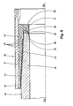
- This second means is shown in enlarged form in FIG. 2 which is a detail of FIG. 1. It shows the zone of introduction (12) of the ring (6) around the tube (1). We see that, in the vicinity of the insertion edge (13) of the ring (6) is arranged a lip (14) oriented radially in the direction of the axis (X l -X 2 ) which bears on the outer wall of the tube. This lip constitutes the second sealing means. Its dimensions are such that, when the ring is screwed in fully, it is in sealed elastic support on the outside wall of the tube.
- the minimum internal diameter (D l ) of the ring is greater than the internal diameter (D 2 ) of the tube in a running part which allows the passage of tools or gauges.
- the area (15) of the ring which protrudes the end of the tube has reliefs such as (16, 17), formed respectively on its outer and inner walls. These reliefs are substantially parallel to the axis and allow the taking of tools for screwing or unscrewing.
- the thickness of the ring is determined so that it collects the shocks due to the handling of the tube and effectively protects the end zone thereof.
- an additional thickness (18) is produced in the vicinity of the insertion zone (12) of the ring which can be subjected to significant forces and shocks.
- This extra thickness makes it possible in particular to absorb shocks perpendicular to the axis X 1 X 2 .
- Figure 3 shows, in axial half-section the protective device according to the invention mounted at the end of a metallic tube of revolution (19), of axis (X 3 -X 4 ), to protect its junction zone female (20).
- This zone comprises an internal frustoconical thread (21) and a convex frustoconical seal surface (22) forming a stop.
- This tube can also be a connector or sleeve used for the assembly of tubes comprising junction zones with male frustoconical thread.
- the generatrix of the joint surface (22) is inclined by 15 to 25 ° relative to a plane perpendicular to the axis (X 3 -X 4 ).
- This joint surface is connected to the end of the threading area of the tube by a chamfer (24).
- the protective device comprises a monobloc ring (25) of plastic material, provided with an external thread (26) comprising only a few threads, which is screwed fully onto the internal thread of the tube until it is tightened to the stop.
- the abutment zone (27) of the ring has a front face (28) opposite the joint surface (22).
- the annular lip (29), oriented towards the interior of the tube (19), is engaged inside the circle formed by the interior edge (22A) of the joint surface (22).
- This inner edge (22A) is at the intersection of the bearing surface (22) and the inner wall (23) of the tube (19).
- this inner edge (22A) bears against the front face (28) in the connection zone between the outer edge (29A) of the lip (29) and the part of this front face (28) which is opposite the joint surface (22).
- the generator of this part of the front face is inclined relative to that of the seal surface so as to reserve a closed annular volume (30) which can be filled with a protective fluid such as a grease.
- the projection of the lip (29) towards the inside of the tube (19) forms a sort of labyrinth which limits the losses of protective fluid, and therefore the risks of penetration of corrosive fluids, in the event that a loss, d Tightness occurs at the contact between the inner edge (22A) of the seal surface (22) and the front face (28).
- a second sealing means is disposed beyond this thread, relative to the joint surface (22), between the ring and the end region (31) of the tube.
- This second means is an annular lip (32), attached to a recess (33) of the reinforced rear wall (34) of the ring (25) which comes into elastic and sealed abutment on the end face (35) of the tube (20).
- the dimensions of the ring (25) are determined so that, when it is fully screwed, tight contacts are obtained at the same time at the first and second sealing means.
- the thread (21) and enclosed volume (30) are thus protected, in a particularly effective manner against the penetration of corrosive fluids, such as sea water.
- the reinforced annular zone (34) of the ring makes it possible to protect from impact the end zone (31) and the face (35) of the tube.
- This reinforced zone (34) includes reliefs such as (36, 37), respectively arranged on the outer wall and on the inner wall, which allow the taking of screwing or unscrewing tools.
- the minimum internal diameter (D 3 ) of the ring is little less than the internal diameter (D 4 ) of the tube, in a common part to allow the passage of tools or calibers of usual types.
- FIG. 4 shows, in axial half-section, a particular embodiment of a protective device (38) according to the invention produced around the end of a metal tube (39), of XSX axis, provided a male frustoconical thread (40) and, at the end, a concave frustoconical seal bearing surface (41) forming a stop.
- This device comprises a plastic ring (42) .comportant only a few threads (43).
- the ring (42) also comprises a stop zone (47), the lip (48) of which forms the inner edge of the front face (49) bears against the inner edge (50) of the joint surface (41). This lip (48) constitutes the first sealing means.
- a closed annular volume (52) is thus formed between the bearing surface (41) and the front face (49).
- the ring (42) is coated on its outer wall with a metal ferrule (51) which projects beyond the end of the ring beyond the end of the tube and thus protects it from localized shocks.
- This ferrule can, for example, be made of mild steel. It is advantageous to make the connection as solid as possible between the ring and the ferrule. For this, it is possible in particular to use the ferrule as one of the walls of a mold inside which the shaping of the plastic ring is carried out. It is also possible to produce on the inner wall of the ferrule (51) reliefs and / or depressions to which the plastic will hang. Other connecting means are also possible.
- Figure 5 represents, in axial half-section, a protective device (53) according to the invention produced at the end of a metal tube (54) of axis of revolution X 7 X 8 , provided with a thread female frustoconical (55).
- the plastic ring (56) has only a few threads (57), at the large diameter end of its zone of engagement in the end of the tube (54).
- An annular lip (59) formed on the rear edge (60) of the ring is supported on the front edge (61) of the tube (54).
- a stop zone (62) At the front end of the ring (56) is made a stop zone (62).
- an annular lip (63), oriented in the direction of the interior of the tube. (5.4) is engaged inside the circle formed by the interior edge (65) of the joint surface forming stop (66).
- This inner edge (65) is at the intersection of the joint surface (66) and the inner wall (66A) of the tube (54).
- the inner edge (65) is in abutment against the front face (64) in the connection zone between the edge (63A) of the lip (63) and the part of the front face (64) which is opposite the joint surface (66) ,.
- the generator of this front face is inclined relative to that of the seal surface so as to reserve a closed annular volume (67) which can be filled with a protective fluid such as a grease.
- a protective fluid such as a grease.
- the lip (59) which constitutes the second sealing means further improves the protection of the entire space between the ring (56) and the tube (54) which in particular prevents corrosion of the thread of the tube by moisture penetration.
- the ring (6, 25, 42) may include, in the vicinity of its rear end for example, a solid circular wall which sealingly closes the passage through this ring and therefore the inlet of the metal tube on which it is screwed.
- this solid circular wall can be integral with this ferrule itself. This circular wall can also be removable.
Landscapes
- Engineering & Computer Science (AREA)
- Mechanical Engineering (AREA)
- Geology (AREA)
- General Engineering & Computer Science (AREA)
- Life Sciences & Earth Sciences (AREA)
- Mining & Mineral Resources (AREA)
- Geochemistry & Mineralogy (AREA)
- Fluid Mechanics (AREA)
- Environmental & Geological Engineering (AREA)
- General Life Sciences & Earth Sciences (AREA)
- Physics & Mathematics (AREA)
- Joints With Pressure Members (AREA)
- Flanged Joints, Insulating Joints, And Other Joints (AREA)
- Gasket Seals (AREA)
- Buffer Packaging (AREA)
- Protection Of Pipes Against Damage, Friction, And Corrosion (AREA)
- Details Of Indoor Wiring (AREA)
- Laying Of Electric Cables Or Lines Outside (AREA)
- Cable Accessories (AREA)
- Lining Or Joining Of Plastics Or The Like (AREA)
Priority Applications (1)
| Application Number | Priority Date | Filing Date | Title |
|---|---|---|---|
| AT85420003T ATE50851T1 (de) | 1984-01-09 | 1985-01-07 | Schutz fuer rohrgewinde und rohrverbindungskontaktflaechen. |
Applications Claiming Priority (4)
| Application Number | Priority Date | Filing Date | Title |
|---|---|---|---|
| FR8400700 | 1984-01-09 | ||
| FR8400700A FR2557953B1 (fr) | 1984-01-09 | 1984-01-09 | Dispositif protecteur des elements de jonctions filetees de tube |
| FR8419850A FR2575266B1 (fr) | 1984-12-20 | 1984-12-20 | Dispositif protecteur monobloc pour filetages et portees de joint formant butee de tubes metalliques filetes |
| FR8419850 | 1984-12-20 |
Publications (2)
| Publication Number | Publication Date |
|---|---|
| EP0148807A1 true EP0148807A1 (de) | 1985-07-17 |
| EP0148807B1 EP0148807B1 (de) | 1990-03-07 |
Family
ID=26223772
Family Applications (1)
| Application Number | Title | Priority Date | Filing Date |
|---|---|---|---|
| EP85420003A Expired - Lifetime EP0148807B1 (de) | 1984-01-09 | 1985-01-07 | Schutz für Rohrgewinde und Rohrverbindungskontaktflächen |
Country Status (7)
| Country | Link |
|---|---|
| US (1) | US4796668A (de) |
| EP (1) | EP0148807B1 (de) |
| AT (1) | ATE50851T1 (de) |
| BR (1) | BR8504530A (de) |
| DE (1) | DE3576396D1 (de) |
| MX (1) | MX161440A (de) |
| WO (1) | WO1985003104A1 (de) |
Cited By (8)
| Publication number | Priority date | Publication date | Assignee | Title |
|---|---|---|---|---|
| EP0328832A3 (de) * | 1987-12-24 | 1991-02-27 | Abdul Hameed Quraishi | Schutzkappenfür die Enden von Rohrförmigen Gegenständen |
| FR2912730A1 (fr) * | 2007-02-21 | 2008-08-22 | Vallourec Mannesmann Oil Gas F | Dispositif de protection d'une extremite femelle d'un composant de joint tubulaire, a frein anti-devissage. |
| WO2014079811A1 (en) | 2012-11-26 | 2014-05-30 | Vallourec Oil And Gas France | Device for protecting a male end of a component of a flexible-joint threaded tubular connection |
| WO2016102848A1 (fr) | 2014-12-23 | 2016-06-30 | Vallourec Oil And Gas France | Dispositif de protection d'une extrémité d'un composant de joint fileté tubulaire a joint souple |
| WO2016102846A1 (fr) | 2014-12-22 | 2016-06-30 | Vallourec Oil And Gas France | Protecteur de connexion d'un composant tubulaire à joint souple |
| WO2016102847A1 (fr) | 2014-12-23 | 2016-06-30 | Vallourec Oil And Gas France | Protecteur d'extremite male ou femelle d'un composant de joint filete tubulaire a joint souple |
| EP3117132A4 (de) * | 2014-03-10 | 2017-11-08 | Saint-Gobain Performance Plastics Corporation | Rohrkupplung |
| US10487594B2 (en) | 2014-10-24 | 2019-11-26 | Vallourec Oil And Gas France | Tubular component connection protector |
Families Citing this family (91)
| Publication number | Priority date | Publication date | Assignee | Title |
|---|---|---|---|---|
| US5303743A (en) * | 1991-05-08 | 1994-04-19 | Vincent Larry W | Thread protection system |
| US5352383A (en) * | 1991-10-18 | 1994-10-04 | Centrax International Corp. | Corrosion inhibitor and sealable thread protector end cap for tubular goods |
| US5441780A (en) * | 1994-03-07 | 1995-08-15 | Jefferson Smurfit Corporation | Paper tube with integral end supports |
| GB2337091A (en) * | 1997-02-21 | 1999-11-10 | Maxtube Limited | Pipe connection assembly |
| GB9703622D0 (en) * | 1997-02-21 | 1997-04-09 | Maxtube Limited | Pipe connection system |
| CN1190616C (zh) * | 1998-05-22 | 2005-02-23 | 筑泰克专利技术有限公司 | 螺纹保护装置 |
| GB9817246D0 (en) * | 1998-08-08 | 1998-10-07 | Petroline Wellsystems Ltd | Connector |
| US6712154B2 (en) * | 1998-11-16 | 2004-03-30 | Enventure Global Technology | Isolation of subterranean zones |
| US7603758B2 (en) | 1998-12-07 | 2009-10-20 | Shell Oil Company | Method of coupling a tubular member |
| US7121352B2 (en) | 1998-11-16 | 2006-10-17 | Enventure Global Technology | Isolation of subterranean zones |
| US7231985B2 (en) * | 1998-11-16 | 2007-06-19 | Shell Oil Company | Radial expansion of tubular members |
| US6745845B2 (en) * | 1998-11-16 | 2004-06-08 | Shell Oil Company | Isolation of subterranean zones |
| US6823937B1 (en) | 1998-12-07 | 2004-11-30 | Shell Oil Company | Wellhead |
| US6634431B2 (en) * | 1998-11-16 | 2003-10-21 | Robert Lance Cook | Isolation of subterranean zones |
| AU6981001A (en) * | 1998-11-16 | 2002-01-02 | Shell Oil Co | Radial expansion of tubular members |
| US6557640B1 (en) * | 1998-12-07 | 2003-05-06 | Shell Oil Company | Lubrication and self-cleaning system for expansion mandrel |
| US6575240B1 (en) | 1998-12-07 | 2003-06-10 | Shell Oil Company | System and method for driving pipe |
| US7357188B1 (en) * | 1998-12-07 | 2008-04-15 | Shell Oil Company | Mono-diameter wellbore casing |
| US7363984B2 (en) | 1998-12-07 | 2008-04-29 | Enventure Global Technology, Llc | System for radially expanding a tubular member |
| US20070051520A1 (en) * | 1998-12-07 | 2007-03-08 | Enventure Global Technology, Llc | Expansion system |
| GB2344606B (en) | 1998-12-07 | 2003-08-13 | Shell Int Research | Forming a wellbore casing by expansion of a tubular member |
| US7195064B2 (en) | 1998-12-07 | 2007-03-27 | Enventure Global Technology | Mono-diameter wellbore casing |
| US6739392B2 (en) * | 1998-12-07 | 2004-05-25 | Shell Oil Company | Forming a wellbore casing while simultaneously drilling a wellbore |
| US7552776B2 (en) * | 1998-12-07 | 2009-06-30 | Enventure Global Technology, Llc | Anchor hangers |
| US7185710B2 (en) * | 1998-12-07 | 2007-03-06 | Enventure Global Technology | Mono-diameter wellbore casing |
| CA2310878A1 (en) * | 1998-12-07 | 2000-12-07 | Shell Internationale Research Maatschappij B.V. | Lubrication and self-cleaning system for expansion mandrel |
| AU770359B2 (en) * | 1999-02-26 | 2004-02-19 | Shell Internationale Research Maatschappij B.V. | Liner hanger |
| US7055608B2 (en) | 1999-03-11 | 2006-06-06 | Shell Oil Company | Forming a wellbore casing while simultaneously drilling a wellbore |
| CA2306656C (en) * | 1999-04-26 | 2006-06-06 | Shell Internationale Research Maatschappij B.V. | Expandable connector for borehole tubes |
| US7350563B2 (en) * | 1999-07-09 | 2008-04-01 | Enventure Global Technology, L.L.C. | System for lining a wellbore casing |
| US6564875B1 (en) * | 1999-10-12 | 2003-05-20 | Shell Oil Company | Protective device for threaded portion of tubular member |
| US7048067B1 (en) | 1999-11-01 | 2006-05-23 | Shell Oil Company | Wellbore casing repair |
| US7516790B2 (en) * | 1999-12-03 | 2009-04-14 | Enventure Global Technology, Llc | Mono-diameter wellbore casing |
| US7234531B2 (en) * | 1999-12-03 | 2007-06-26 | Enventure Global Technology, Llc | Mono-diameter wellbore casing |
| US7100684B2 (en) | 2000-07-28 | 2006-09-05 | Enventure Global Technology | Liner hanger with standoffs |
| CA2466685C (en) | 2000-09-18 | 2010-11-23 | Shell Oil Company | Liner hanger with sliding sleeve valve |
| WO2002029199A1 (en) | 2000-10-02 | 2002-04-11 | Shell Oil Company | Method and apparatus for casing expansion |
| US7100685B2 (en) | 2000-10-02 | 2006-09-05 | Enventure Global Technology | Mono-diameter wellbore casing |
| CA2428819A1 (en) * | 2001-01-03 | 2002-07-11 | Enventure Global Technology | Mono-diameter wellbore casing |
| US7410000B2 (en) * | 2001-01-17 | 2008-08-12 | Enventure Global Technology, Llc. | Mono-diameter wellbore casing |
| AU2002318438A1 (en) * | 2001-07-06 | 2003-01-21 | Enventure Global Technology | Liner hanger |
| GB2394979B (en) * | 2001-07-06 | 2005-11-02 | Eventure Global Technology | Liner hanger |
| US7258168B2 (en) | 2001-07-27 | 2007-08-21 | Enventure Global Technology L.L.C. | Liner hanger with slip joint sealing members and method of use |
| US20050217866A1 (en) * | 2002-05-06 | 2005-10-06 | Watson Brock W | Mono diameter wellbore casing |
| US7793721B2 (en) * | 2003-03-11 | 2010-09-14 | Eventure Global Technology, Llc | Apparatus for radially expanding and plastically deforming a tubular member |
| WO2003023178A2 (en) | 2001-09-07 | 2003-03-20 | Enventure Global Technology | Adjustable expansion cone assembly |
| GB2421258B (en) * | 2001-11-12 | 2006-08-09 | Enventure Global Technology | Mono diameter wellbore casing |
| WO2003058022A2 (en) * | 2001-12-27 | 2003-07-17 | Enventure Global Technology | Seal receptacle using expandable liner hanger |
| US7377326B2 (en) * | 2002-08-23 | 2008-05-27 | Enventure Global Technology, L.L.C. | Magnetic impulse applied sleeve method of forming a wellbore casing |
| WO2004027786A2 (en) * | 2002-09-20 | 2004-04-01 | Enventure Global Technology | Protective sleeve for expandable tubulars |
| US7424918B2 (en) | 2002-08-23 | 2008-09-16 | Enventure Global Technology, L.L.C. | Interposed joint sealing layer method of forming a wellbore casing |
| EP1985797B1 (de) * | 2002-04-12 | 2011-10-26 | Enventure Global Technology | Schutzhülse für Gewindeverbindungen für eine ausdehnbare Liner-Aufhängvorrichtung |
| CA2482278A1 (en) | 2002-04-15 | 2003-10-30 | Enventure Global Technology | Protective sleeve for threaded connections for expandable liner hanger |
| GB2406125B (en) * | 2002-05-29 | 2006-11-01 | Enventure Global Technology | Radially expanding a tubular member |
| AU2003274310A1 (en) * | 2002-06-10 | 2003-12-22 | Enventure Global Technology | Mono-diameter wellbore casing |
| AU2003275962A1 (en) * | 2002-06-12 | 2003-12-31 | Eventure Global Technology | Collapsible expansion cone |
| WO2004009950A1 (en) * | 2002-07-24 | 2004-01-29 | Enventure Global Technology | Dual well completion system |
| AU2003253782A1 (en) * | 2002-07-29 | 2004-02-16 | Enventure Global Technology | Method of forming a mono diameter wellbore casing |
| GB0221585D0 (en) * | 2002-09-17 | 2002-10-23 | Weatherford Lamb | Tubing connection arrangement |
| CA2499030A1 (en) * | 2002-09-20 | 2004-04-01 | Enventure Global Technology | Mono diameter wellbore casing |
| US7739917B2 (en) * | 2002-09-20 | 2010-06-22 | Enventure Global Technology, Llc | Pipe formability evaluation for expandable tubulars |
| AU2003263852A1 (en) | 2002-09-20 | 2004-04-08 | Enventure Global Technology | Self-lubricating expansion mandrel for expandable tubular |
| WO2004023014A2 (en) * | 2002-09-20 | 2004-03-18 | Enventure Global Technlogy | Threaded connection for expandable tubulars |
| CA2499007C (en) * | 2002-09-20 | 2012-08-07 | Enventure Global Technology | Bottom plug for forming a mono diameter wellbore casing |
| AU2003293388A1 (en) * | 2002-12-05 | 2004-06-30 | Enventure Global Technology | System for radially expanding tubular members |
| US7886831B2 (en) * | 2003-01-22 | 2011-02-15 | Enventure Global Technology, L.L.C. | Apparatus for radially expanding and plastically deforming a tubular member |
| JP2006517011A (ja) | 2003-01-27 | 2006-07-13 | エンベンチャー グローバル テクノロジー | 管状部材放射状拡大用潤滑システム |
| GB2429225B (en) * | 2003-02-18 | 2007-11-28 | Enventure Global Technology | Protective sleeves with sacrificial material-filled reliefs for threaded connections of radially expandable tubular members |
| GB2429996B (en) * | 2003-02-26 | 2007-08-29 | Enventure Global Technology | Apparatus for radially expanding and plastically deforming a tubular member |
| GB2415988B (en) | 2003-04-17 | 2007-10-17 | Enventure Global Technology | Apparatus for radially expanding and plastically deforming a tubular member |
| US20050166387A1 (en) * | 2003-06-13 | 2005-08-04 | Cook Robert L. | Method and apparatus for forming a mono-diameter wellbore casing |
| US7712522B2 (en) | 2003-09-05 | 2010-05-11 | Enventure Global Technology, Llc | Expansion cone and system |
| DE602005016075D1 (de) * | 2004-02-02 | 2009-10-01 | Tenaris Connections Ag | Gewindeschutz für röhrenförmige glieder |
| US7819185B2 (en) | 2004-08-13 | 2010-10-26 | Enventure Global Technology, Llc | Expandable tubular |
| US7469721B2 (en) * | 2004-08-25 | 2008-12-30 | Sumitomo Metal Industries, Ltd. | Thread protector for a pipe |
| WO2007014339A2 (en) * | 2005-07-27 | 2007-02-01 | Enventure Global Technology, L.L.C. | Method and apparatus for coupling expandable tubular members |
| AR051775A1 (es) * | 2005-11-22 | 2007-02-07 | Siderca Sa Ind & Com | Un conjunto protector par el extremo roscado de un tubo y de su interior que comprende un protector roscado abierto y una tapa ciega encastrable al mismo |
| CN201170063Y (zh) * | 2007-08-03 | 2008-12-24 | 乔士军 | 钻杆螺纹保护器 |
| AU2009352058B2 (en) * | 2009-09-02 | 2014-07-24 | Drilltec Patents & Technologies Corporation | Protector for tubular threaded joint |
| NL2003992C2 (en) * | 2009-12-21 | 2011-06-22 | Pipe Proteq B V | Wellbore pipe protection device. |
| FR2964408B1 (fr) * | 2010-09-03 | 2013-05-03 | Premium Protector | Protecteur de tube d'extraction de petrole |
| CA2860499C (en) * | 2012-01-19 | 2018-01-16 | Yasuhiro Yamamoto | Box protector for a threaded joint for pipes |
| US20140326350A1 (en) * | 2013-05-01 | 2014-11-06 | Timothy Riley | Tailpipe customization |
| US10113681B2 (en) | 2013-05-16 | 2018-10-30 | Lockheed Martin Corporation | Pressure compensated enclosures for submerged joints |
| WO2018203877A1 (en) * | 2017-05-01 | 2018-11-08 | Fmc Technologies, Inc. | Sealing profile protector |
| WO2019206484A1 (en) * | 2018-04-25 | 2019-10-31 | Peter Kroll | System and protector for protecting an end of a pipe |
| NL2021001B1 (en) * | 2018-05-29 | 2019-12-04 | Tenaris Connections Bv | Pipe end protector |
| USD1025308S1 (en) | 2019-11-25 | 2024-04-30 | Universal Moulding Co. Ltd. | Pipe thread protector |
| NL2024342B1 (en) * | 2019-11-29 | 2021-08-31 | Siderca Sa Ind & Com | Pipe end protector |
| US11828128B2 (en) * | 2021-01-04 | 2023-11-28 | Saudi Arabian Oil Company | Convertible bell nipple for wellbore operations |
| CA3147967A1 (en) | 2021-02-04 | 2022-08-04 | Universal Moulding Co. Ltd. | Pipe thread protector with removable end member, seal assembly, and interference ring, and end member and seal assembly therefor |
Citations (9)
| Publication number | Priority date | Publication date | Assignee | Title |
|---|---|---|---|---|
| GB380450A (en) * | 1930-09-09 | 1932-09-13 | Nat Supply Corp | Improvement in packed drill pipe joints or couplings |
| US2239942A (en) * | 1939-05-17 | 1941-04-29 | Hydril Company Of California | Well pipe joint |
| US2258066A (en) * | 1940-03-11 | 1941-10-07 | Youngstown Sheet And Tube Co | Pipe joint |
| FR872393A (fr) * | 1939-06-10 | 1942-06-05 | Deutsche Rohrenwerke Ag | Protection des filetages de tubes |
| FR1187881A (fr) * | 1956-10-29 | 1959-09-17 | Protecteurs thermoplastiques pour bouts de tuyaux | |
| US2930118A (en) * | 1956-08-06 | 1960-03-29 | Edward F Higgins | Method of manufacturing a box end thread protector for sucker rod couplings and the like |
| FR2215363A1 (de) * | 1973-01-29 | 1974-08-23 | Nova Hut Klementa Gottwalda | |
| DE2715837A1 (de) * | 1977-04-05 | 1978-10-12 | Mannesmann Ag | Schutzring fuer rohre |
| US4157100A (en) * | 1977-08-17 | 1979-06-05 | John Turk | Thread protector device |
Family Cites Families (8)
| Publication number | Priority date | Publication date | Assignee | Title |
|---|---|---|---|---|
| FR1489013A (fr) * | 1965-11-05 | 1967-07-21 | Vallourec | Joint d'assemblage pour tubes métalliques |
| US3578200A (en) * | 1969-11-03 | 1971-05-11 | Gti Corp | Port protectors |
| IE46133B1 (en) * | 1977-01-07 | 1983-03-09 | Quraisha A | Protectors for the ends of tubular elements |
| US4210179A (en) * | 1978-12-21 | 1980-07-01 | United States Steel Corporation | Pipe-thread protector |
| DE3100527C2 (de) * | 1981-01-10 | 1984-01-12 | Wilhelm Strödter Maschinen- und Apparatebau, 4700 Hamm | Schutzkappe und Schutznippel für Enden von Rohren, insbesondere von Ölfeldrohren |
| GB2093426B (en) * | 1981-02-23 | 1985-06-12 | Pennsylvania Plastic Prod | A protective cap for pipe threads |
| US4582090A (en) * | 1983-04-26 | 1986-04-15 | Hydril Company | Tubular member thread protector |
| US4487228A (en) * | 1983-12-19 | 1984-12-11 | Shell Oil Company | Weather-resistant and self-draining thread protector |
-
1984
- 1984-01-07 US US06/763,140 patent/US4796668A/en not_active Expired - Fee Related
-
1985
- 1985-01-07 BR BR8504530A patent/BR8504530A/pt not_active IP Right Cessation
- 1985-01-07 WO PCT/FR1985/000003 patent/WO1985003104A1/fr not_active Ceased
- 1985-01-07 AT AT85420003T patent/ATE50851T1/de not_active IP Right Cessation
- 1985-01-07 EP EP85420003A patent/EP0148807B1/de not_active Expired - Lifetime
- 1985-01-07 DE DE8585420003T patent/DE3576396D1/de not_active Expired - Lifetime
- 1985-01-08 MX MX203983A patent/MX161440A/es unknown
Patent Citations (9)
| Publication number | Priority date | Publication date | Assignee | Title |
|---|---|---|---|---|
| GB380450A (en) * | 1930-09-09 | 1932-09-13 | Nat Supply Corp | Improvement in packed drill pipe joints or couplings |
| US2239942A (en) * | 1939-05-17 | 1941-04-29 | Hydril Company Of California | Well pipe joint |
| FR872393A (fr) * | 1939-06-10 | 1942-06-05 | Deutsche Rohrenwerke Ag | Protection des filetages de tubes |
| US2258066A (en) * | 1940-03-11 | 1941-10-07 | Youngstown Sheet And Tube Co | Pipe joint |
| US2930118A (en) * | 1956-08-06 | 1960-03-29 | Edward F Higgins | Method of manufacturing a box end thread protector for sucker rod couplings and the like |
| FR1187881A (fr) * | 1956-10-29 | 1959-09-17 | Protecteurs thermoplastiques pour bouts de tuyaux | |
| FR2215363A1 (de) * | 1973-01-29 | 1974-08-23 | Nova Hut Klementa Gottwalda | |
| DE2715837A1 (de) * | 1977-04-05 | 1978-10-12 | Mannesmann Ag | Schutzring fuer rohre |
| US4157100A (en) * | 1977-08-17 | 1979-06-05 | John Turk | Thread protector device |
Cited By (13)
| Publication number | Priority date | Publication date | Assignee | Title |
|---|---|---|---|---|
| EP0328832A3 (de) * | 1987-12-24 | 1991-02-27 | Abdul Hameed Quraishi | Schutzkappenfür die Enden von Rohrförmigen Gegenständen |
| US9206930B2 (en) | 2007-02-21 | 2015-12-08 | Vallourec Oil And Gas France | Device for protecting a female end of a threaded tubular connection component, having an anti-unscrewing brake |
| WO2008116986A1 (fr) * | 2007-02-21 | 2008-10-02 | Vallourec Mannesmann Oil & Gas France | Dispositif de protection d'une extrémité femelle d'un composant de joint fileté tubulaire, à frein anti-dévissage |
| RU2444672C2 (ru) * | 2007-02-21 | 2012-03-10 | Валлурек Маннесманн Ойл Энд Гэс Франс | Устройство для защиты охватывающего конца компонента трубчатого резьбового соединения с антиотвинчивающим торможением |
| CN101617164B (zh) * | 2007-02-21 | 2012-04-18 | 瓦卢莱克曼内斯曼油气法国公司 | 具有防松扣制动的螺纹管接头元件的阴端保护装置 |
| FR2912730A1 (fr) * | 2007-02-21 | 2008-08-22 | Vallourec Mannesmann Oil Gas F | Dispositif de protection d'une extremite femelle d'un composant de joint tubulaire, a frein anti-devissage. |
| WO2014079811A1 (en) | 2012-11-26 | 2014-05-30 | Vallourec Oil And Gas France | Device for protecting a male end of a component of a flexible-joint threaded tubular connection |
| US9611971B2 (en) | 2012-11-26 | 2017-04-04 | Vallourec Oil And Gas France | Device for protecting a male end of a component of a flexible-joint threaded tubular connection |
| EP3117132A4 (de) * | 2014-03-10 | 2017-11-08 | Saint-Gobain Performance Plastics Corporation | Rohrkupplung |
| US10487594B2 (en) | 2014-10-24 | 2019-11-26 | Vallourec Oil And Gas France | Tubular component connection protector |
| WO2016102846A1 (fr) | 2014-12-22 | 2016-06-30 | Vallourec Oil And Gas France | Protecteur de connexion d'un composant tubulaire à joint souple |
| WO2016102848A1 (fr) | 2014-12-23 | 2016-06-30 | Vallourec Oil And Gas France | Dispositif de protection d'une extrémité d'un composant de joint fileté tubulaire a joint souple |
| WO2016102847A1 (fr) | 2014-12-23 | 2016-06-30 | Vallourec Oil And Gas France | Protecteur d'extremite male ou femelle d'un composant de joint filete tubulaire a joint souple |
Also Published As
| Publication number | Publication date |
|---|---|
| DE3576396D1 (de) | 1990-04-12 |
| BR8504530A (pt) | 1985-12-24 |
| US4796668A (en) | 1989-01-10 |
| EP0148807B1 (de) | 1990-03-07 |
| WO1985003104A1 (fr) | 1985-07-18 |
| MX161440A (es) | 1990-09-26 |
| ATE50851T1 (de) | 1990-03-15 |
Similar Documents
| Publication | Publication Date | Title |
|---|---|---|
| EP0148807B1 (de) | Schutz für Rohrgewinde und Rohrverbindungskontaktflächen | |
| EP0867596B1 (de) | Gewindeverbinder für Rohre | |
| EP0780617B1 (de) | Schraubverbindung für innenbeschichtete Metallrohre | |
| FR2760064A1 (fr) | Raccord traversant et systeme a double confinement de fluide | |
| EP0140171A1 (de) | Dichtung für Verbindungen von gusseisernen Rohren | |
| WO2013093338A1 (fr) | Raccordement pour tube et tuyau polyethylene utilise dans l'adduction de l'eau | |
| FR2576658A1 (fr) | Structure d'etancheite | |
| FR2528533A1 (fr) | Raccord traversant a ecrou tournant pour gaine exterieurement spiralee | |
| FR2557953A1 (fr) | Dispositif protecteur des elements de jonctions filetees de tube | |
| EP0470918B1 (de) | Verbindung zwischen Rohrelementen | |
| FR2575266A1 (fr) | Dispositif protecteur monobloc pour filetages et portees de joint formant butee de tubes metalliques filetes | |
| CA2018741C (fr) | Rouleau conducteur de courant | |
| EP1605195B1 (de) | Rohrkupplungssystem und dazu gehöriges Montageverfahren | |
| EP1963730B1 (de) | Vorrichtung und verfahren zum anbohren einer rohrleitung mit abzweigsattel | |
| FR2785359A1 (fr) | Collier de prise en charge a bague anti-fluage de joint et procede de fabrication | |
| EP0581678A1 (de) | Radiale Spannvorrichtung zum Verbinden von einem Rohr mit einem Rohrende | |
| FR2554538A1 (fr) | Joint d'etancheite pour branchement d'un element tubulaire sur un tuyau de plus grand diametre | |
| LU79883A1 (fr) | Emboitement de canalisation | |
| CA1092621A (fr) | Raccord entre conduites plastique et metallique pour traversee de facade d'un abonne au gaz | |
| FR2543369A2 (fr) | Dispositif d'etancheite pour connecteur electrique | |
| FR1411836A (fr) | Pompe de bicyclette | |
| FR2672372A1 (fr) | Dispositif de jonction etanche entre deux tuyaux cylindriques. | |
| FR2737763A1 (fr) | Piece formant joint et dispositif comprenant la piece formant joint | |
| EP0538113B1 (de) | Stromleiterrollen für Elektrolyseeinrichtungen | |
| FR2657144A3 (fr) | Raccord a blocage rapide pour tuyaux en matiere plastique ou produits similaires. |
Legal Events
| Date | Code | Title | Description |
|---|---|---|---|
| PUAI | Public reference made under article 153(3) epc to a published international application that has entered the european phase |
Free format text: ORIGINAL CODE: 0009012 |
|
| AK | Designated contracting states |
Designated state(s): AT BE DE GB IT NL SE |
|
| 17P | Request for examination filed |
Effective date: 19850806 |
|
| 17Q | First examination report despatched |
Effective date: 19860917 |
|
| D17Q | First examination report despatched (deleted) | ||
| RAP1 | Party data changed (applicant data changed or rights of an application transferred) |
Owner name: VALLOUREC |
|
| GRAA | (expected) grant |
Free format text: ORIGINAL CODE: 0009210 |
|
| AK | Designated contracting states |
Kind code of ref document: B1 Designated state(s): AT BE DE GB IT NL SE |
|
| REF | Corresponds to: |
Ref document number: 50851 Country of ref document: AT Date of ref document: 19900315 Kind code of ref document: T |
|
| ITF | It: translation for a ep patent filed | ||
| GBT | Gb: translation of ep patent filed (gb section 77(6)(a)/1977) | ||
| REF | Corresponds to: |
Ref document number: 3576396 Country of ref document: DE Date of ref document: 19900412 |
|
| PLBE | No opposition filed within time limit |
Free format text: ORIGINAL CODE: 0009261 |
|
| STAA | Information on the status of an ep patent application or granted ep patent |
Free format text: STATUS: NO OPPOSITION FILED WITHIN TIME LIMIT |
|
| 26N | No opposition filed | ||
| PGFP | Annual fee paid to national office [announced via postgrant information from national office to epo] |
Ref country code: GB Payment date: 19921214 Year of fee payment: 9 |
|
| PGFP | Annual fee paid to national office [announced via postgrant information from national office to epo] |
Ref country code: BE Payment date: 19921215 Year of fee payment: 9 |
|
| PGFP | Annual fee paid to national office [announced via postgrant information from national office to epo] |
Ref country code: DE Payment date: 19921228 Year of fee payment: 9 Ref country code: AT Payment date: 19921228 Year of fee payment: 9 |
|
| PGFP | Annual fee paid to national office [announced via postgrant information from national office to epo] |
Ref country code: SE Payment date: 19921229 Year of fee payment: 9 |
|
| PGFP | Annual fee paid to national office [announced via postgrant information from national office to epo] |
Ref country code: NL Payment date: 19930131 Year of fee payment: 9 |
|
| REG | Reference to a national code |
Ref country code: GB Ref legal event code: 732E |
|
| PG25 | Lapsed in a contracting state [announced via postgrant information from national office to epo] |
Ref country code: GB Effective date: 19940107 Ref country code: AT Effective date: 19940107 |
|
| PG25 | Lapsed in a contracting state [announced via postgrant information from national office to epo] |
Ref country code: SE Effective date: 19940108 |
|
| PG25 | Lapsed in a contracting state [announced via postgrant information from national office to epo] |
Ref country code: BE Effective date: 19940131 |
|
| BERE | Be: lapsed |
Owner name: VALLOUREC Effective date: 19940131 |
|
| PG25 | Lapsed in a contracting state [announced via postgrant information from national office to epo] |
Ref country code: NL Effective date: 19940801 |
|
| GBPC | Gb: european patent ceased through non-payment of renewal fee |
Effective date: 19940107 |
|
| NLV4 | Nl: lapsed or anulled due to non-payment of the annual fee | ||
| PG25 | Lapsed in a contracting state [announced via postgrant information from national office to epo] |
Ref country code: DE Effective date: 19941001 |
|
| EUG | Se: european patent has lapsed |
Ref document number: 85420003.7 Effective date: 19940810 |