EP0148996A1 - Accouplement de surcharge pour porte-mèche à serrage rapide - Google Patents
Accouplement de surcharge pour porte-mèche à serrage rapide Download PDFInfo
- Publication number
- EP0148996A1 EP0148996A1 EP84110366A EP84110366A EP0148996A1 EP 0148996 A1 EP0148996 A1 EP 0148996A1 EP 84110366 A EP84110366 A EP 84110366A EP 84110366 A EP84110366 A EP 84110366A EP 0148996 A1 EP0148996 A1 EP 0148996A1
- Authority
- EP
- European Patent Office
- Prior art keywords
- coupling
- ball
- balls
- drive
- cage
- Prior art date
- Legal status (The legal status is an assumption and is not a legal conclusion. Google has not performed a legal analysis and makes no representation as to the accuracy of the status listed.)
- Granted
Links
- 238000005520 cutting process Methods 0.000 title description 4
- 230000008878 coupling Effects 0.000 claims abstract description 170
- 238000010168 coupling process Methods 0.000 claims abstract description 170
- 238000005859 coupling reaction Methods 0.000 claims abstract description 170
- 238000010079 rubber tapping Methods 0.000 claims abstract description 5
- 230000002093 peripheral effect Effects 0.000 claims description 5
- 239000000463 material Substances 0.000 claims description 4
- 230000002441 reversible effect Effects 0.000 claims description 4
- 230000005540 biological transmission Effects 0.000 claims description 3
- 229920001971 elastomer Polymers 0.000 claims description 2
- 239000005060 rubber Substances 0.000 claims description 2
- 229920003051 synthetic elastomer Polymers 0.000 claims description 2
- 239000005061 synthetic rubber Substances 0.000 claims description 2
- 238000007789 sealing Methods 0.000 claims 1
- 230000036316 preload Effects 0.000 abstract description 2
- 230000008901 benefit Effects 0.000 description 6
- 230000006835 compression Effects 0.000 description 5
- 238000007906 compression Methods 0.000 description 5
- 238000004519 manufacturing process Methods 0.000 description 4
- 230000009471 action Effects 0.000 description 1
- 230000008859 change Effects 0.000 description 1
- 238000010276 construction Methods 0.000 description 1
- 238000011161 development Methods 0.000 description 1
- 230000018109 developmental process Effects 0.000 description 1
- 229910003460 diamond Inorganic materials 0.000 description 1
- 239000010432 diamond Substances 0.000 description 1
- 238000006073 displacement reaction Methods 0.000 description 1
- 238000005553 drilling Methods 0.000 description 1
- 230000000694 effects Effects 0.000 description 1
- 238000005516 engineering process Methods 0.000 description 1
- 230000003993 interaction Effects 0.000 description 1
- 238000003754 machining Methods 0.000 description 1
- 238000000034 method Methods 0.000 description 1
- 230000005012 migration Effects 0.000 description 1
- 238000013508 migration Methods 0.000 description 1
- 230000035515 penetration Effects 0.000 description 1
- 230000002028 premature Effects 0.000 description 1
- 230000008569 process Effects 0.000 description 1
- 230000004044 response Effects 0.000 description 1
- 230000000717 retained effect Effects 0.000 description 1
- 230000035939 shock Effects 0.000 description 1
- 230000001960 triggered effect Effects 0.000 description 1
Images
Classifications
-
- F—MECHANICAL ENGINEERING; LIGHTING; HEATING; WEAPONS; BLASTING
- F16—ENGINEERING ELEMENTS AND UNITS; GENERAL MEASURES FOR PRODUCING AND MAINTAINING EFFECTIVE FUNCTIONING OF MACHINES OR INSTALLATIONS; THERMAL INSULATION IN GENERAL
- F16D—COUPLINGS FOR TRANSMITTING ROTATION; CLUTCHES; BRAKES
- F16D7/00—Slip couplings, e.g. slipping on overload, for absorbing shock
- F16D7/04—Slip couplings, e.g. slipping on overload, for absorbing shock of the ratchet type
- F16D7/06—Slip couplings, e.g. slipping on overload, for absorbing shock of the ratchet type with intermediate balls or rollers
- F16D7/10—Slip couplings, e.g. slipping on overload, for absorbing shock of the ratchet type with intermediate balls or rollers moving radially between engagement and disengagement
-
- B—PERFORMING OPERATIONS; TRANSPORTING
- B23—MACHINE TOOLS; METAL-WORKING NOT OTHERWISE PROVIDED FOR
- B23B—TURNING; BORING
- B23B31/00—Chucks; Expansion mandrels; Adaptations thereof for remote control
- B23B31/02—Chucks
- B23B31/38—Chucks with overload clutches
-
- B—PERFORMING OPERATIONS; TRANSPORTING
- B23—MACHINE TOOLS; METAL-WORKING NOT OTHERWISE PROVIDED FOR
- B23B—TURNING; BORING
- B23B2215/00—Details of workpieces
- B23B2215/68—Threaded components
-
- Y—GENERAL TAGGING OF NEW TECHNOLOGICAL DEVELOPMENTS; GENERAL TAGGING OF CROSS-SECTIONAL TECHNOLOGIES SPANNING OVER SEVERAL SECTIONS OF THE IPC; TECHNICAL SUBJECTS COVERED BY FORMER USPC CROSS-REFERENCE ART COLLECTIONS [XRACs] AND DIGESTS
- Y10—TECHNICAL SUBJECTS COVERED BY FORMER USPC
- Y10T—TECHNICAL SUBJECTS COVERED BY FORMER US CLASSIFICATION
- Y10T408/00—Cutting by use of rotating axially moving tool
- Y10T408/70—Tool or tool-support with torque-applying clutch
Definitions
- the invention relates to an overload coupling device for tapping chucks or quick-change inserts for these, with otherwise the features in the preamble of claim 1.
- the drive sleeve expediently has three cage slots which follow one another in the circumferential direction at approximately equal angular intervals, in each of which a coupling ball is held straight with sufficient movement play. Taking this play into account, the slot width therefore corresponds approximately to the ball diameter.
- the wall of each cage slot which, when the ball pocket coupling is triggered, lifts the coupling balls out of the ball pockets and pushes them in front of one another, is designed here in such a way that the coupling balls remain in this uncoupled position when uncoupling and do not tend to automatically return to the ball pockets when they pass through them relapse with brief clutch engagement.
- the overload clutch device works precisely and reliably and reliably disconnects from the drive when the tripping torque is reached. This is supported by Special design of the axially acting surfaces of the spring-loaded pressure ring on the coupling balls. The individual advantages achieved thereby are described in detail in DE-PS 25 11 148. You therefore do not need to be repeated here.
- Both surface sections converge in a corner area, which lies essentially on a circumferential circle which is larger than the circumferential circle circumscribing the outer circumferential surface of the drive shaft and on which approximately the center points of the coupling balls located in the ball pockets lie in the coupled state.
- a cage slot wall which is subdivided into two individual surfaces that run at an angle to one another, means a considerable outlay in terms of production technology.
- the invention is therefore based on the object to provide an overload coupling device of the type mentioned in the preamble of claim 1, which is simple and cheap in construction while maintaining all the advantages achieved thereby, allows small axial and especially radial dimensions e, low wear and with respect of the response behavior works reliably and precisely, which furthermore reliably and permanently separates from the drive when the triggering torque is reached without any sudden stresses, and which also increases the wear resistance in the area between the cage slots and the balls and at the same time can be manufactured more easily and cheaply.
- three cage slots of the first group and three cage slots of the second group are provided, each with first and second coupling balls held therein.
- the second coupling balls which are supported in the second cage slots with a larger circumferential extent, essentially only have a real coupling task if, after uncoupling in the working drive direction, the coupling is to be recoupled by rotating them in opposite directions. In this direction opposite to the working drive direction, the second coupling balls in the second cage slots act as elements transmitting the return torque.
- the torque to be transmitted in the coupled state in the working drive direction is invariably from the first clutch balls transferred in the first cage slots.
- These first cage slots are smoothly continuous from the inside to the outside with respect to their opposing walls. They are therefore easier to manufacture.
- the so responsive ball pocket coupling then separates the drive shaft, which until then was driven via the drive sleeve and the engaged ball pocket coupling, with a tap held therein.
- the drive sleeve which is still driven, can rotate freely with a fixed drive shaft with a tap. This protects the tap and the drill hole against damage, breaking and flank breaking.
- the second coupling balls of the second cage slots also have the task of supporting the thrust ring, which is under axial spring pressure, when the first coupling balls reach ball pockets during rotation and strive to get into the ball pockets with a sudden coupling. If the second coupling balls were not in the second cage slots If this were present, this recoupling would take place with subsequent recoupling.
- the result would be changing and sudden torque loads for the tap and the workpiece, but also for the machine tool during machining. Since one of the two coupling balls, either the first coupling ball or the second coupling ball, is always under radial and axial preload when the clutch is activated and disconnected, while the other coupling ball is relieved and free, these shock loads are avoided.
- the second coupling balls are automatically pushed back over the one, inclined wall of the second cage slots in the direction of and into the ball pockets, whereby the compression springs of the pressure ring are relieved.
- the overload clutch device according to the invention therefore leads entirely to the same advantages as the known overload clutch device mentioned, with the particular advantage achieved of an even further minimized wear and tear and still further reduced production outlay, in particular reduced costs.
- the additional three second coupling balls and the additional spring element are not significant in terms of cost.
- first cage slots namely one wall of these
- second cage slots namely one wall of the latter
- the inclinations of the individual walls acting on the first and second coupling balls can be correspondingly of these cage slots each independently and so determine how it is most useful for decoupling or coupling in the opposite direction.
- This is also a decisive advantage over known coupling devices of this type.
- the upper load coupling device is still neither larger in terms of the axial dimension nor the radial dimension.
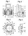
- the quick-change insert 10 is known, except for the special features described below (DE-PS 25 11 148), both with regard to its structural design and its mode of operation. To avoid repetition, reference is therefore made to DE-PS 25 11 148, only the most important elements for understanding and the new design features being explained below.
- the quick-change insert 10 for a tap (not shown further) has a cylindrical drive shaft 12 and a cylindrical drive sleeve 13, which is rotatably held coaxially with the drive shaft 12 and has a two axially projecting, diametrically opposite drive cams 16 at the top in FIG. 1. If the quick-change insert 10 is inserted into an associated quick-change chuck (not shown) for thread cutting, the drive cams 16 take torque with the quick-change chuck.
- This working drive direction is indicated by arrow 18. It runs in Fig. 1, viewed from above in the axial direction on the quick-change insert 10, clockwise and in Fig. 3, 5 to 7 in the counterclockwise direction.
- a torque coupling designed as a ball pocket coupling 19 with adjustable, triggering torque.
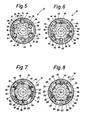
- This is spring loaded. It has a first group of three coupling balls 20 which are arranged at equal angular distances from one another in the circumferential direction, and a second group of likewise three coupling balls 63 which are likewise arranged at equal angular distances from one another in the circumferential direction, which essentially each have the same circumferential angular distances in the coupled position (FIG. 5) of the coupling balls 20 of the first group.
- the drive sleeve 13 contains a first group of cage slots 23, in each of which a coupling ball 20 is received.
- the first cage slots 23 follow one another in the circumferential direction essentially at equal angular intervals.
- the cage slots 23 and 64 are open in the axial and radial directions, in the latter inwards and outwards. Their axial depth is smaller than the diameter of each assigned coupling ball 20 or 63, so that they can project downwards in the axial direction in FIGS. 1, 2 over the lower end of the drive sleeve 13.
- the slot width of the first cage slots 23 is at least as large as the diameter of the coupling balls 20.
- the second cage slots 64 have a considerably larger slot width in relation to the diameter of the coupling balls 63. This can e.g. up to twice the diameter of the coupling balls 63.
- the diameter of the coupling balls 20 and that of the coupling balls 63 is expediently the same size, so that only one type of ball is used.
- the drive shaft 12 has in the axial region of the cage slots 23 and 64 on its outer circumferential surface 24 for the coupling balls 20 and for the second coupling balls 63 a total of six ball pockets 25 and 65 arranged in the circumferential direction at equal angular intervals from one another.
- the ball pockets 25 and 65 are recessed and have a spherical cap shape a lesser Depth than the sphere radius.
- the ball pockets 25 serve for receiving the coupling balls 20 and the ball pockets 65 for receiving the coupling balls 63 in the coupled position shown in FIG. 5.
- All cage slots 23 and 64 are inclined against the working drive direction according to arrow 18 of the drive sleeve 13. Details will be explained later.
- an end sleeve 26 is axially immovable, which coaxially surrounds the drive sleeve 13 and the drive shaft 12.
- the end sleeve 26 contains in the axial area of all the cage slots 23, 64 an annular groove 28 inside, the groove base of which runs at least at a radial distance corresponding to the diameter of the coupling balls 20, 63 from the peripheral surface 24.
- each first cage slot 23 that face each other with the slot width strive, at least weakly, when viewed radially outward V-shaped apart.
- the other wall 51 runs approximately on a diametral.
- the walls 66 and 67 facing each other with the slot width, as seen in the radial direction, also diverge at least weakly in a V-shape.
- One wall 66 runs in the working drive direction according to arrow 18 when the ball pocket coupling 19 responds to the associated coupling ball 63 in the sense of being lifted out of its ball pocket 65 (FIG. 7) and then pushes the coupling ball 63 in front of itself, also approximately a diamond.
- the other wall 67 runs on a secant approximately parallel to the diametral.
- the second cage slots 64 transmit a drive torque with the one wall 67 in the reverse direction of rotation (FIG. 8) to the working drive direction according to arrow 18, so that in this direction a screw tap is forcibly unscrewed from the threaded hole.
- Both walls 51 and 66 of the first cage slot 23 and the second cage slot 64 which run approximately on a diametral, run at least essentially along one and the same diametral, as shown in FIG.
- the two walls 51, 66 are formed by the two sides of a relatively thin material web 68 running approximately in this direction. In this way, the first and second cage slots 23 and 64 are grouped in pairs and closely adjacent in the circumferential direction.
- an all-round spring element 70 is arranged on the drive shaft 12, as is not shown, or, as the exemplary embodiment shows, on the end sleeve 26.
- the spring element consists of a ring made of elastically deformable material, in particular of rubber or synthetic rubber, and here preferably of a commercially available O-ring which is radially prestressed between the annular groove 28 and the outer peripheral surface of the drive sleeve 13.
- the spring element 70 is located at the axial and radial height of the cage slots 23, 64 and is at least partially received there within a circumferential groove 71, which is contained within the annular groove 28.
- the inclusion in the circumferential groove 71 is such that the spring element 70 in the unstressed state (FIG. 2) radially, seen from the outside inwards, projects over the bottom of the annular groove 28 into the annular space between the circumferential surface 24 of the drive shaft 12 and the annular groove 28 .
- the spring element 70 can exert a radial force, here directed radially from the outside inwards, on the first coupling balls 20 and second coupling balls 63.
- the spring element 70 exerts a radial force that the respective coupling ball 20, 63 between the peripheral surface 24 of the drive shaft 12 and the annular groove 28 of the end sleeve 26 biases.
- the coupling ball 20 or 63 lifted out of the coupling position and its ball pocket 25 or 65 is respectively preloaded held because the pressed-out coupling ball 20 or 63 presses radially from the inside against the spring element 70, which dodges and exerts an opposing force on the coupling ball 20, 63.
- the coupling ball 20 or 63 which is pushed out into the annulus mentioned, lies both inside and outside. There is contact at both points. It can thereby be achieved that when the ball pocket coupling 19 responds, the radially migrating coupling balls 20, 63 are driven relative to the blocked, fixed drive shaft 12 with a relative rotation of the still driven drive sleeve 13 and always keep the same distance in the working drive direction according to arrow 18.
- the operation of the quick-change insert 10, in particular the ball pocket coupling 19 as a torque coupling, is very similar to that of a known type (DE-PS 25 11 148).
- Fig. 5 shows the coupled initial state in which the thread cutting process takes place.
- the first coupling balls 20, which are responsible for the torque transmission in this state, are stored within their ball pockets 25 and are held in the ball pockets 25 by means of the pressure ring 29 via the pressure springs 30 with a preset spring force.
- the flow of force during the threading process runs over the drive cams 16 of the drive sleeve 13, over the cage slots 23, there in particular the walls 50, onto the first coupling balls 20 stored therein and from there over the ball pockets 25 to the drive shaft 12 and taps held in a rotationally fixed manner therein.
- the second coupling balls 63 have no torque-transmitting effect, since the second coupling balls 63 are located far from the wall 66 near the opposite wall 67.
- the tap runs into the bottom of the blind hole during blind drilling or otherwise due to incorrect depth adjustment or if the core hole is not drilled deep enough, the tap is stopped on the workpiece side.
- a braking torque on the drill side counteracts the drive torque. If the braking torque is greater than the preset triggering torque of the ball pocket coupling 19, then a decoupling takes place automatically between the drive sleeve 13 and the drive shaft 12 with a tap.
- the ball pocket coupling 19 responds. First, the first coupling balls 20 are lifted out of the ball pockets 25 via the wall 5C, and this against the axial spring loading of the pressure ring 29.
- the radial outward movement of the coupling balls 20 into the annular groove 28 is a corresponding axial displacement of the pressure ring 29 against the action of the compression spring 30 overlaid. If the first coupling balls 20 are completely pushed out of their ball pockets 25, they are pressed radially from the inside to the outside by compressing the spring element 70 against the latter and held between them in a spring-elastic clamping manner (FIG. 6).
- the second coupling balls 63 still remain in their ball pockets 65, for as long as the walls 66 of the second cage slots 64 run up against the second coupling balls 63 in the circumferential direction during the relative rotation between the drive sleeve 13 and the stationary drive shaft 12.
- the first coupling balls 20, reinforced by the axial pressure of the springs 30 and the pressure ring 29, remain in the uncoupled position during this relative rotary movement (FIG. 6).
- the second coupling balls 63 become from their ball pockets 65 radially lifted out (Fig. 7).
- the first coupling balls 20 are still biased radially and axially in the manner described.
- first coupling balls 20 reach radially inwards into these second ball pockets 65.
- the first coupling balls 20 can freely enter the ball pockets 65 without jerky movement, because even before the second coupling balls 63 have been lifted out of these ball pockets 65, the second coupling balls 63 now have the pressure ring 29 which presses axially thereon via the compression springs 30 hold and block against axial penetration. Also now the second coupling balls 63 are clamped in the radial direction in the annular space by means of the spring element 70 so that an inner and outer contact occurs.
- the second coupling balls 63 After passing through a further circumferential angle, the second coupling balls 63 return to the ball pockets 25 that follow next in the circumferential direction, the first coupling balls 20 having been lifted out of their coupling position (FIG. 5) shortly beforehand via the walls 50 of the first cage slots 23, approximately into the position 6.
- the uncoupling of the coupling balls 20 also takes place without jerky loading of the torque coupling as well as the tap and the machine, because before the coupling balls 20 are lifted out of the ball pockets there are still others
- Coupling balls 63 are in the disengaged position and via this the spring-loaded pressure ring 29 is retained axially in this holding position, so that it cannot be advanced axially while releasing the compression springs 30.
- one group of the coupling balls 20 or 63 always acts as such, which radially escapes into the annular groove 28 by compressing the spring element 70 and axially absorbs the pressure force of the pressure ring 29 acting thereon, while the other group is currently free and unloaded.
- the first coupling balls 20 and the second coupling balls 63 whereby the other group is always free to move and yet - during this intermediate phase, neither axial nor radial relaxation can take place, which would otherwise result in a jerky recoupling with subsequent connection would result in jerky disengagement, with all the disadvantages resulting therefrom.
- the ball pocket coupling 19 of this type is particularly simple, inexpensive to produce and leads to small dimensions. If the tap runs open during thread cutting, it is relieved. The risk that the drill bit will break out or break at all is averted, or at least greatly reduced. The danger of the flank breaking is prevented. It is also advantageous that there are no impressions of the coupling balls due to hammering and striking on the shaft, which was otherwise the case when the torque coupling responded and alternately uncoupling and falling back into the coupled position. Since no impacts are transmitted, greater accuracy can be achieved. This applies in particular to fine threads. The wear of the entire ball pocket coupling is significantly less. It is also advantageous that the machine tool is also less stressed, since no blows are exerted on the workpiece and from the quick-change insert on the machine spindle.
- the ball pocket coupling 19 is thereby returned to the coupled state in that an opposing torque directed against the arrow 18 is exerted on the drive sleeve 13 (FIG. 8).
- the second clutch balls 63 are effective for torque transmission. They are inevitably put back into the next ball pockets 25 or 65 by the very obliquely directed wall 67 in an approximately radial direction. The return movement occurs suddenly and quickly. The inclination of the wall 67 during the return movement ensures that the drive shaft 12 is forcibly carried along with a tap. This is necessary because during the return rotation the tap must be unscrewed from the cut threaded hole without destroying it.
- the torque limitation achieved by the ball pocket coupling 19 is therefore only effective if the drive direction corresponds to that according to arrow 18. In the opposite return movement, the torque clutch 19 is inoperative. 'The torque driving is then performed on the second cage slots 64, where the walls 67 and the second coupling balls 63rd
- the coupling balls 20 can - before the second coupling balls 63 are pressed into their ball pockets - immerse themselves again in their ball pockets. Therefore, the one wall 51 of the first cage slots 23 must have such an angular orientation that no significant torque occurs in the reverse direction and thereby the tap may be unscrewed before the second coupling balls 63 are acted upon in the reverse direction via the walls 67.
Landscapes
- Engineering & Computer Science (AREA)
- General Engineering & Computer Science (AREA)
- Mechanical Engineering (AREA)
- One-Way And Automatic Clutches, And Combinations Of Different Clutches (AREA)
- Gripping On Spindles (AREA)
- Mechanical Operated Clutches (AREA)
Applications Claiming Priority (2)
| Application Number | Priority Date | Filing Date | Title |
|---|---|---|---|
| DE3345948A DE3345948C2 (de) | 1983-12-20 | 1983-12-20 | Überlastkupplungseinrichtung für Gewindeschneidfutter oder Schnellwechseleinsätze für diese |
| DE3345948 | 1983-12-20 |
Publications (2)
| Publication Number | Publication Date |
|---|---|
| EP0148996A1 true EP0148996A1 (fr) | 1985-07-24 |
| EP0148996B1 EP0148996B1 (fr) | 1987-04-22 |
Family
ID=6217407
Family Applications (1)
| Application Number | Title | Priority Date | Filing Date |
|---|---|---|---|
| EP84110366A Expired EP0148996B1 (fr) | 1983-12-20 | 1984-08-31 | Accouplement de surcharge pour porte-mèche à serrage rapide |
Country Status (5)
| Country | Link |
|---|---|
| US (1) | US4599019A (fr) |
| EP (1) | EP0148996B1 (fr) |
| JP (1) | JPS60131117A (fr) |
| DE (1) | DE3345948C2 (fr) |
| IN (1) | IN163534B (fr) |
Cited By (2)
| Publication number | Priority date | Publication date | Assignee | Title |
|---|---|---|---|---|
| GB2180476A (en) * | 1985-09-19 | 1987-04-01 | France Realisa Outillage Sarl | Quick change adapter with a torque limiter for a tapping chuck |
| EP0260240A3 (en) * | 1986-09-10 | 1988-05-18 | S & L Maskin Ab | Settable slip clutch |
Families Citing this family (23)
| Publication number | Priority date | Publication date | Assignee | Title |
|---|---|---|---|---|
| JPH078106Y2 (ja) * | 1987-09-03 | 1995-03-01 | 株式会社日研工作所 | タップホルダーのクラッチ機構 |
| US5174424A (en) * | 1988-10-13 | 1992-12-29 | Tapmatic International Corporation (Tic Ag) | Arrangement in screw thread cutting apparatus |
| US4929128A (en) * | 1989-06-23 | 1990-05-29 | Affleck Robert J | Masonry drill assembly |
| US5067600A (en) * | 1991-02-13 | 1991-11-26 | Emerson Electric Co. | Precision overload clutch apparatus for automated machinery |
| DE4134919A1 (de) * | 1991-09-27 | 1993-04-08 | Ringspann Gmbh | Rastanordnung fuer den schaltbolzen eines ueberlastelementes, insbesondere an einer ueberlastkupplung |
| US5464229A (en) * | 1994-05-26 | 1995-11-07 | Power Tool Holders, Inc. | Quick release chuck device |
| US5573255A (en) * | 1995-05-05 | 1996-11-12 | Power Tool Holders, Inc. | Quick release chuck device for saw blades |
| US5951024A (en) * | 1997-08-11 | 1999-09-14 | Power Tool Holders Incorporated | Enhanced grip tool holding chuck |
| US5947484A (en) * | 1997-09-03 | 1999-09-07 | Power Tool Holders Incorporated | Quick-change chuck device |
| DE10318820A1 (de) * | 2003-04-16 | 2004-11-11 | Alfred Kärcher Gmbh & Co. Kg | Überlastkupplung |
| US7219583B1 (en) * | 2005-12-23 | 2007-05-22 | Sunmatch Industrial Co., Ltd. | Pneumatic screwdriver having an adjustable clockwise torque and a maximum counterclockwise torque |
| DE102009052526A1 (de) * | 2008-11-12 | 2010-05-27 | Neumayer Tekfor Holding Gmbh | Dämpfereinheit für eine Welle |
| US8882384B2 (en) * | 2010-04-16 | 2014-11-11 | Moeller Manufacturing Co., Inc. | Compact, highly-reusable, locking device |
| US8920519B2 (en) * | 2012-02-01 | 2014-12-30 | The Johns Hopkins University | Multiple grasp prosthetic terminal device |
| DE102013205000A1 (de) * | 2013-03-21 | 2014-09-25 | M.A.T. Malmedie Antriebstechnik Gmbh | Überlastschutzvorrichtung für Seilstränge |
| US20150102567A1 (en) * | 2013-10-16 | 2015-04-16 | Fu-Yi Chan | Tool joint |
| US9909446B2 (en) * | 2014-10-03 | 2018-03-06 | Kurt Kevin Bynum | Self-locking plug |
| US9593700B2 (en) | 2014-10-03 | 2017-03-14 | Kurt Kevin Bynum | Self-locking plug |
| US20180056401A1 (en) * | 2016-08-25 | 2018-03-01 | Yu-Chieh Lin | Adjustable Chuck Apparatus for Screw Tap |
| EP4121606A4 (fr) | 2020-03-16 | 2024-04-10 | Kohler Co. | Mécanisme de couplage rapide pour toilettes et procédé d'utilisation de celui-ci |
| FR3117081B1 (fr) * | 2020-12-05 | 2022-11-18 | Ckp Eng | Procédé et système de neutralisation de remontées de secousses supportées par une colonne de direction de véhicule. |
| CN112548238A (zh) * | 2020-12-31 | 2021-03-26 | 刘梅峰 | 一种夹头 |
| CN116690327A (zh) * | 2022-02-25 | 2023-09-05 | 广东博智林机器人有限公司 | 过载保护传动机构及打磨机 |
Citations (7)
| Publication number | Priority date | Publication date | Assignee | Title |
|---|---|---|---|---|
| US3263451A (en) * | 1964-03-23 | 1966-08-02 | Hayes Steel Products Ltd | Torque overload control device |
| DE1810223B2 (de) * | 1967-11-24 | 1971-09-23 | Ueberlastkupplung insbesondere an einem spannfutter fuer werkzeuge mit einem schaftende | |
| DE1602701B2 (de) * | 1967-02-04 | 1974-01-10 | Otto Bilz, Werkzeugfabrik, 7302 Nellingen | Bohrerfutter mit einer Sicherheitseinrichtung gegen Überlastung des Werkzeugs |
| DE2233130A1 (de) * | 1972-07-06 | 1974-01-31 | Bosch Gmbh Robert | Sicherheitskupplung |
| DE2328464A1 (de) * | 1973-06-05 | 1974-12-19 | Bilz Otto Werkzeug | Gewindeschneidfutter mit ausloesender drehmomentkupplung |
| DE2923141A1 (de) * | 1978-06-08 | 1979-12-13 | Manyo Tool | Werkzeughalter |
| DE2511148B2 (de) * | 1975-03-14 | 1980-09-11 | Otto Bilz Werkzeugfabrik, 7302 Ostfildern | Überlastkupplungseinrichtung für Gewindeschneidfutter oder Schnellwechseleinsätze für diese |
Family Cites Families (3)
| Publication number | Priority date | Publication date | Assignee | Title |
|---|---|---|---|---|
| US1681288A (en) * | 1925-07-18 | 1928-08-21 | Nat Automatic Tool Co | Positive tapping mechanism for multiple-spindle machines |
| GB383516A (en) * | 1932-03-23 | 1932-11-17 | William Warren Triggs | Improvements in safety clutch mechanisms |
| US3787136A (en) * | 1973-01-02 | 1974-01-22 | Numertap Inc | Adjustable torque controlled tool holder |
-
1983
- 1983-12-20 DE DE3345948A patent/DE3345948C2/de not_active Expired
-
1984
- 1984-03-06 JP JP59043725A patent/JPS60131117A/ja active Granted
- 1984-08-31 EP EP84110366A patent/EP0148996B1/fr not_active Expired
- 1984-09-22 IN IN668/CAL/84A patent/IN163534B/en unknown
- 1984-10-25 US US06/664,885 patent/US4599019A/en not_active Expired - Lifetime
Patent Citations (7)
| Publication number | Priority date | Publication date | Assignee | Title |
|---|---|---|---|---|
| US3263451A (en) * | 1964-03-23 | 1966-08-02 | Hayes Steel Products Ltd | Torque overload control device |
| DE1602701B2 (de) * | 1967-02-04 | 1974-01-10 | Otto Bilz, Werkzeugfabrik, 7302 Nellingen | Bohrerfutter mit einer Sicherheitseinrichtung gegen Überlastung des Werkzeugs |
| DE1810223B2 (de) * | 1967-11-24 | 1971-09-23 | Ueberlastkupplung insbesondere an einem spannfutter fuer werkzeuge mit einem schaftende | |
| DE2233130A1 (de) * | 1972-07-06 | 1974-01-31 | Bosch Gmbh Robert | Sicherheitskupplung |
| DE2328464A1 (de) * | 1973-06-05 | 1974-12-19 | Bilz Otto Werkzeug | Gewindeschneidfutter mit ausloesender drehmomentkupplung |
| DE2511148B2 (de) * | 1975-03-14 | 1980-09-11 | Otto Bilz Werkzeugfabrik, 7302 Ostfildern | Überlastkupplungseinrichtung für Gewindeschneidfutter oder Schnellwechseleinsätze für diese |
| DE2923141A1 (de) * | 1978-06-08 | 1979-12-13 | Manyo Tool | Werkzeughalter |
Cited By (4)
| Publication number | Priority date | Publication date | Assignee | Title |
|---|---|---|---|---|
| GB2180476A (en) * | 1985-09-19 | 1987-04-01 | France Realisa Outillage Sarl | Quick change adapter with a torque limiter for a tapping chuck |
| FR2589766A1 (fr) * | 1985-09-19 | 1987-05-15 | Realisa Outillage Ste Fse Et | Adapteur a changement rapide et a limiteur de couple pour mandrin de taraudage. |
| GB2180476B (en) * | 1985-09-19 | 1989-08-31 | Etudes Realis Outillage | Quick change adapter with a torque limiter for a tapping chuck |
| EP0260240A3 (en) * | 1986-09-10 | 1988-05-18 | S & L Maskin Ab | Settable slip clutch |
Also Published As
| Publication number | Publication date |
|---|---|
| DE3345948A1 (de) | 1985-06-27 |
| IN163534B (fr) | 1988-10-08 |
| EP0148996B1 (fr) | 1987-04-22 |
| DE3345948C2 (de) | 1987-04-23 |
| US4599019A (en) | 1986-07-08 |
| JPS60131117A (ja) | 1985-07-12 |
| JPH0314573B2 (fr) | 1991-02-27 |
Similar Documents
| Publication | Publication Date | Title |
|---|---|---|
| EP0148996B1 (fr) | Accouplement de surcharge pour porte-mèche à serrage rapide | |
| DE2511148C3 (de) | Überlastkupplungseinrichtung für Gewindeschneidfutter oder Schnellwechseleinsätze für diese | |
| EP0854773B1 (fr) | Outil inserable et porte-outil pour machines electriques a percer et/ou percutantes | |
| DE19827172B4 (de) | Werkzeughalter, insbesondere für Bohr-oder Schlaghämmer | |
| DE3507817C2 (fr) | ||
| DE2148352C3 (de) | Überlast-Abschaltkupplung | |
| DE1777171B2 (de) | Spannfutter zum schnellen Auswechseln von Werkzeugen | |
| DE4100186A1 (de) | Handwerkzeugmaschine mit abnehmbaren werkzeughalter | |
| DE2715357A1 (de) | Werkzeugaufnahmevorrichtung | |
| DE3437269C2 (fr) | ||
| DE69607809T2 (de) | Spannfutter für schneidwerkzeug | |
| EP0756099B1 (fr) | Embrayage | |
| DE1527166A1 (de) | Gewindeschneidapparat | |
| DE3516541C2 (de) | Werkzeughalter | |
| CH663557A5 (de) | Bohrfutter zum schlagbohren. | |
| EP0768151B1 (fr) | Porte-outil | |
| DE1270371B (de) | Drehmoment-UEberlastsicherung an einer Gewindeschneidvorrichtung | |
| DE19715269C1 (de) | Kupplung zur Drehmomentbegrenzung | |
| DE2353741A1 (de) | Kombinationswerkzeug | |
| DE2624734C3 (de) | Gewindebohrfutter | |
| CH664104A5 (de) | Bohrfutter. | |
| DE3411670A1 (de) | Gewindebohrwerkzeug-aufnahmefutter | |
| DE1959770A1 (de) | Gewindeschneidvorrichtung | |
| DE3844311A1 (de) | Bohrmaschine | |
| DE884446C (de) | Gewindeschneidapparat |
Legal Events
| Date | Code | Title | Description |
|---|---|---|---|
| PUAI | Public reference made under article 153(3) epc to a published international application that has entered the european phase |
Free format text: ORIGINAL CODE: 0009012 |
|
| AK | Designated contracting states |
Designated state(s): FR GB IT |
|
| 17P | Request for examination filed |
Effective date: 19850830 |
|
| 17Q | First examination report despatched |
Effective date: 19860926 |
|
| GRAA | (expected) grant |
Free format text: ORIGINAL CODE: 0009210 |
|
| AK | Designated contracting states |
Kind code of ref document: B1 Designated state(s): FR GB IT |
|
| ET | Fr: translation filed | ||
| ITF | It: translation for a ep patent filed | ||
| PLBE | No opposition filed within time limit |
Free format text: ORIGINAL CODE: 0009261 |
|
| STAA | Information on the status of an ep patent application or granted ep patent |
Free format text: STATUS: NO OPPOSITION FILED WITHIN TIME LIMIT |
|
| 26N | No opposition filed | ||
| ITTA | It: last paid annual fee | ||
| PGFP | Annual fee paid to national office [announced via postgrant information from national office to epo] |
Ref country code: FR Payment date: 20010618 Year of fee payment: 18 |
|
| PGFP | Annual fee paid to national office [announced via postgrant information from national office to epo] |
Ref country code: GB Payment date: 20010716 Year of fee payment: 18 |
|
| REG | Reference to a national code |
Ref country code: GB Ref legal event code: IF02 |
|
| PG25 | Lapsed in a contracting state [announced via postgrant information from national office to epo] |
Ref country code: GB Free format text: LAPSE BECAUSE OF NON-PAYMENT OF DUE FEES Effective date: 20020831 |
|
| GBPC | Gb: european patent ceased through non-payment of renewal fee |
Effective date: 20020831 |
|
| PG25 | Lapsed in a contracting state [announced via postgrant information from national office to epo] |
Ref country code: FR Free format text: LAPSE BECAUSE OF NON-PAYMENT OF DUE FEES Effective date: 20030430 |
|
| REG | Reference to a national code |
Ref country code: FR Ref legal event code: ST |