EP0149013A2 - Getriebesteuerung mit geschwindigkeitsabhängigem Drosselventil zur Modifizierung des Schlupfes - Google Patents
Getriebesteuerung mit geschwindigkeitsabhängigem Drosselventil zur Modifizierung des Schlupfes Download PDFInfo
- Publication number
- EP0149013A2 EP0149013A2 EP84111976A EP84111976A EP0149013A2 EP 0149013 A2 EP0149013 A2 EP 0149013A2 EP 84111976 A EP84111976 A EP 84111976A EP 84111976 A EP84111976 A EP 84111976A EP 0149013 A2 EP0149013 A2 EP 0149013A2
- Authority
- EP
- European Patent Office
- Prior art keywords
- friction element
- valve
- control system
- orifice
- transmission control
- Prior art date
- Legal status (The legal status is an assumption and is not a legal conclusion. Google has not performed a legal analysis and makes no representation as to the accuracy of the status listed.)
- Withdrawn
Links
Images
Classifications
-
- F—MECHANICAL ENGINEERING; LIGHTING; HEATING; WEAPONS; BLASTING
- F16—ENGINEERING ELEMENTS AND UNITS; GENERAL MEASURES FOR PRODUCING AND MAINTAINING EFFECTIVE FUNCTIONING OF MACHINES OR INSTALLATIONS; THERMAL INSULATION IN GENERAL
- F16H—GEARING
- F16H61/00—Control functions within control units of change-speed- or reversing-gearings for conveying rotary motion ; Control of exclusively fluid gearing, friction gearing, gearings with endless flexible members or other particular types of gearing
- F16H61/04—Smoothing ratio shift
- F16H61/06—Smoothing ratio shift by controlling rate of change of fluid pressure
- F16H61/065—Smoothing ratio shift by controlling rate of change of fluid pressure using fluid control means
- F16H61/068—Smoothing ratio shift by controlling rate of change of fluid pressure using fluid control means using an orifice control valve
-
- F—MECHANICAL ENGINEERING; LIGHTING; HEATING; WEAPONS; BLASTING
- F16—ENGINEERING ELEMENTS AND UNITS; GENERAL MEASURES FOR PRODUCING AND MAINTAINING EFFECTIVE FUNCTIONING OF MACHINES OR INSTALLATIONS; THERMAL INSULATION IN GENERAL
- F16H—GEARING
- F16H61/00—Control functions within control units of change-speed- or reversing-gearings for conveying rotary motion ; Control of exclusively fluid gearing, friction gearing, gearings with endless flexible members or other particular types of gearing
- F16H61/04—Smoothing ratio shift
- F16H61/06—Smoothing ratio shift by controlling rate of change of fluid pressure
- F16H61/065—Smoothing ratio shift by controlling rate of change of fluid pressure using fluid control means
- F16H61/067—Smoothing ratio shift by controlling rate of change of fluid pressure using fluid control means using an accumulator
Definitions
- the present invention relates generally to an automatic automotive transmission hydraulic control system and more specifically to a system which includes an orifice valve which modifies the rate at which a friction element is engaged.
- an orifice valve- is arranged to be responsive to a vehicle speed signal (e.g governor pressure) in a manner to establish a second fluid path between (a) the friction element (e.g. clutch) and an accumulator associated therewith and (b) the valve (e.g. 3-4 shift valve) which supplys the actuating pressurized hydraulic fluid and therefore reduce the flow restriction between the shift valve and the friction element when the vehicle is speed is above a predetermined value.
- a vehicle speed signal e.g governor pressure
- the present invention takes the form of a transmission control system for a transmission having an output shaft, which includes a friction element which is engageable to produce a forward speed ratio, a first device for selectively supplying hydraulic fluid under pressure to the friction element through a first flow restriction, a second device which produces a signal which varies with an operational parameter of the transmission, and which features an orifice valve interposed between the first device and the friction element for decreasing the flow restriction between the first device and the friction element in response to the magnitude of the signal increasing above a predetermined level.
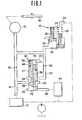
- Fig. 1 shows schematically a first embodiment of the present invention.
- the transmission into which this embodiment of the invention is incorporated is a.four forward speed planetary gear transmssion and that the friction element 10 is in fact a clutch which is engaged during a 4 -3 downshift.
- the present invention may be applied reference may be had to applicant's copending U.S. Parent Application Serial No. 518,413 filed on July 29, 1983 in the name of Sugano, or applicant's corresponding copending European Patent Application No. 83107503.1 filed on July 29, 1983.
- valve which characterizes the present invention may be used in conjunction with clutch C3 and accumulator 140 disclosed in the above mentioned documents but is not specifically limited to same and may find application in conjunction with any other friction element/accumulator arrangement wherein a variable orifice effect is desirable.
- friction element 10 is arranged to be supplied line pressure from a 3-4 shift valve 12 via conduit 14.
- a first flow restriction or orifice 16 is disposed in conduit 14 and an accumulator 18 arranged to communicate with conduit 14 a location downstream of the orifice 16.
- This accumulator 18 includes a stepped piston 20 which is reciprocatively disposed in a stepped bore 22.
- a spring 24 is arranged to bias the piston 20 in a direction which minimizes the volume of a chamber 26 which is in fluid communication with friction element 10. Line pressure is supplied to a chamber 28 of the accumulator via conduit 29.
- An orifice valve 30 which characterizes the present invention, in this embodiment takes the form of a spool valve including a bore 32 in which ports 33, 34, 35 & 36 are formed and a spool valve element 39 having first and second lands 37, 38 thereon. As shown, the spool is received in bore so as to define variable volume chambers at each end thereof.
- the upper chamber. 40 communicates with port 33 which in this instance acts as a drain.
- the lower chamber 42 is communicated via port 36 with the governor valve 44 of the transmission via conduit 46.
- a spring 48 is disposed in the upper chamber 40 and arranged to bias the spool valve element 34 in a direction.to minimize the volume of chamber 42.
- Port 35 of the orifice valve is. arranged to communicate with conduit 14 at a location upstream of the orifice 16 while port 34 is arranged to communicate with both of the accumulator 18 and conduit 16 (at a location downstream of orifice) via a conduit 50.
- a second orifice 52 is disposed in conduit 50.
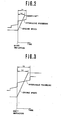
- Figs. 2 and 3 show the engagement characteristics which may be derived at high and low vehicle speeds, respectively.
- Fig. 2 when both orifices 16, 52 are used, at time t i seconds after the initiation of the shift, the hydraulic pressure in the friction element 10 maximizes. At a time t 1 ' seconds the engine RPM ceases to increase and becomes constant. In comparison when only one orifice (viz., orifice 16) is available (see Fig. 3), the time at which the pressure in the friction element 10 maximizes is increased to t 2 seconds while the engine speed levels off after a period of t 2 ' seconds.
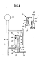
- Fig. 4 shows a second embodiment of the present invention.
- This embodiment differs from the first in that the second orifice 52 is replaced by a third land 60 on the spool valve element 34.
- this land 60 is is arranged to have a diameter slightly less than the section of the bore in which it reciprocates and thus cause a flow restriction beteen ports 34 and 35 when the spool valve element 34' assumes the position illustrated by the left hand half section.
Landscapes
- Engineering & Computer Science (AREA)
- General Engineering & Computer Science (AREA)
- Physics & Mathematics (AREA)
- Fluid Mechanics (AREA)
- Mechanical Engineering (AREA)
- Control Of Transmission Device (AREA)
Applications Claiming Priority (2)
| Application Number | Priority Date | Filing Date | Title |
|---|---|---|---|
| JP187085/83 | 1983-10-07 | ||
| JP18708583A JPS6081553A (ja) | 1983-10-07 | 1983-10-07 | 自動変速機の油圧制御装置 |
Publications (2)
| Publication Number | Publication Date |
|---|---|
| EP0149013A2 true EP0149013A2 (de) | 1985-07-24 |
| EP0149013A3 EP0149013A3 (de) | 1985-09-25 |
Family
ID=16199853
Family Applications (1)
| Application Number | Title | Priority Date | Filing Date |
|---|---|---|---|
| EP84111976A Withdrawn EP0149013A3 (de) | 1983-10-07 | 1984-10-05 | Getriebesteuerung mit geschwindigkeitsabhängigem Drosselventil zur Modifizierung des Schlupfes |
Country Status (2)
| Country | Link |
|---|---|
| EP (1) | EP0149013A3 (de) |
| JP (1) | JPS6081553A (de) |
Cited By (4)
| Publication number | Priority date | Publication date | Assignee | Title |
|---|---|---|---|---|
| EP0281304A1 (de) * | 1987-02-27 | 1988-09-07 | Toyota Jidosha Kabushiki Kaisha | Hydraulisches Steuerungssystem für ein automatisches Getriebe |
| EP0356036A3 (de) * | 1988-08-02 | 1992-03-04 | Toyota Jidosha Kabushiki Kaisha | Hydraulische Steuerung für ein automatisches Fahrzeuggetriebe mit einer Kupplung mit zwei Schaltzuständen und zwei parallelen Druckversorgungsleitungen dafür |
| EP0503691A1 (de) * | 1991-03-11 | 1992-09-16 | General Motors Corporation | Steuerung für den geregelten Eingriff einer flüssigkeitsbetriebenen Drehmomentübertragungseinrichtung |
| EP0661479A1 (de) * | 1993-12-30 | 1995-07-05 | Agco Corporation | Steuerung mit Ladedruckerfassung für ein Lastschaltgetriebe |
Family Cites Families (4)
| Publication number | Priority date | Publication date | Assignee | Title |
|---|---|---|---|---|
| US3295387A (en) * | 1963-05-03 | 1967-01-03 | Ford Motor Co | Multiple speed transmission |
| US3683721A (en) * | 1969-09-09 | 1972-08-15 | Toyota Motor Co Ltd | Hydraulic control system for automatic transmissions |
| DE2137160C3 (de) * | 1971-07-24 | 1978-04-20 | Volkswagenwerk Ag, 3180 Wolfsburg | Hydraulische Steuereinrichtung zum selbsttätigen Umschalten eines Kraftfahrzeuggetriebes |
| US4468989A (en) * | 1981-11-09 | 1984-09-04 | Ford Motor Company | Power transmission mechanism with a hydrokinetic torque converter having a lockup clutch |
-
1983
- 1983-10-07 JP JP18708583A patent/JPS6081553A/ja active Pending
-
1984
- 1984-10-05 EP EP84111976A patent/EP0149013A3/de not_active Withdrawn
Cited By (5)
| Publication number | Priority date | Publication date | Assignee | Title |
|---|---|---|---|---|
| EP0281304A1 (de) * | 1987-02-27 | 1988-09-07 | Toyota Jidosha Kabushiki Kaisha | Hydraulisches Steuerungssystem für ein automatisches Getriebe |
| US4843922A (en) * | 1987-02-27 | 1989-07-04 | Toyota Jidosha Kabushiki Kaisha | Hydraulic control system for automatic transmission |
| EP0356036A3 (de) * | 1988-08-02 | 1992-03-04 | Toyota Jidosha Kabushiki Kaisha | Hydraulische Steuerung für ein automatisches Fahrzeuggetriebe mit einer Kupplung mit zwei Schaltzuständen und zwei parallelen Druckversorgungsleitungen dafür |
| EP0503691A1 (de) * | 1991-03-11 | 1992-09-16 | General Motors Corporation | Steuerung für den geregelten Eingriff einer flüssigkeitsbetriebenen Drehmomentübertragungseinrichtung |
| EP0661479A1 (de) * | 1993-12-30 | 1995-07-05 | Agco Corporation | Steuerung mit Ladedruckerfassung für ein Lastschaltgetriebe |
Also Published As
| Publication number | Publication date |
|---|---|
| EP0149013A3 (de) | 1985-09-25 |
| JPS6081553A (ja) | 1985-05-09 |
Similar Documents
| Publication | Publication Date | Title |
|---|---|---|
| US4672864A (en) | Control system for an infinitely variable transmission | |
| US4680987A (en) | Control system for an infinitely variable transmission | |
| EP0213852B1 (de) | Öldrucksteuerung für ein stufenlos veränderbares Getriebe | |
| EP0257960B1 (de) | Steuereinrichtung für ein stufenlos regelbares Getriebe | |
| US4188839A (en) | Throttling control valve and a system for controlling downshift timing of an automatic transmission for vehicles | |
| US4730522A (en) | System for controlling the pressure of oil in a system for a continuously variable transmission | |
| EP0118003A2 (de) | Getriebesteuerung mit Schaltstossunterdrückung | |
| EP0240282A2 (de) | Steuervorrichtung für den Öldruck eines stufenlos regelbaren Getriebes | |
| EP0370425B1 (de) | System zur Steuerung einer Ueberbrückungskupplung | |
| EP0207603B1 (de) | Steuersystem für ein stufenloses Getriebe | |
| US4729265A (en) | Shift shock suppression arrangement for automotive automatic transmission | |
| US5411451A (en) | Control system for controlling the pressure of the oncoming servo hydraulic pressure based on a predicted time to sync from output shaft acceleration in automatic transmission | |
| EP0205257B1 (de) | Leitungsdrucksteuervorrichtung für ein stufenlos regelbares Getriebe | |
| US3452621A (en) | Automatic transmission control | |
| US4787272A (en) | Hydraulic pressure control apparatus for use in automatic transmission | |
| EP0149013A2 (de) | Getriebesteuerung mit geschwindigkeitsabhängigem Drosselventil zur Modifizierung des Schlupfes | |
| US4841814A (en) | System for controlling the pressure of oil in a system for a continuously variable transmission | |
| EP0149012A2 (de) | Getriebesteuerung mit geschwindigkeitsabhängigem Drosselventil zur Modifizierung des Schlupfes | |
| CA1159746A (en) | Hydraulic system pressure control for a power transmission | |
| GB1509519A (en) | Multi-ratio drive transmissions | |
| US4911036A (en) | Pressure regulating arrangement for automatic transmission | |
| GB1229640A (de) | ||
| US5076117A (en) | Orifice control arrangement for automatic automotive transmission | |
| US4930372A (en) | System for engaging lock-up clutch at highest speed ratios of different operation ranges | |
| US4729264A (en) | System for controlling the pressure of oil in a system for a continuously variable transmission |
Legal Events
| Date | Code | Title | Description |
|---|---|---|---|
| PUAI | Public reference made under article 153(3) epc to a published international application that has entered the european phase |
Free format text: ORIGINAL CODE: 0009012 |
|
| 17P | Request for examination filed |
Effective date: 19841005 |
|
| AK | Designated contracting states |
Designated state(s): DE FR GB |
|
| PUAL | Search report despatched |
Free format text: ORIGINAL CODE: 0009013 |
|
| AK | Designated contracting states |
Designated state(s): DE FR GB |
|
| STAA | Information on the status of an ep patent application or granted ep patent |
Free format text: STATUS: THE APPLICATION HAS BEEN WITHDRAWN |
|
| 18W | Application withdrawn |
Withdrawal date: 19860620 |
|
| RIN1 | Information on inventor provided before grant (corrected) |
Inventor name: SUGANO, KAZUHIKO |