EP0149041A2 - Mécanisme pour chaise inclinable - Google Patents
Mécanisme pour chaise inclinable Download PDFInfo
- Publication number
- EP0149041A2 EP0149041A2 EP84113440A EP84113440A EP0149041A2 EP 0149041 A2 EP0149041 A2 EP 0149041A2 EP 84113440 A EP84113440 A EP 84113440A EP 84113440 A EP84113440 A EP 84113440A EP 0149041 A2 EP0149041 A2 EP 0149041A2
- Authority
- EP
- European Patent Office
- Prior art keywords
- chair
- support means
- spring
- tilt mechanism
- compressible
- Prior art date
- Legal status (The legal status is an assumption and is not a legal conclusion. Google has not performed a legal analysis and makes no representation as to the accuracy of the status listed.)
- Granted
Links
Images


Classifications
-
- A—HUMAN NECESSITIES
- A47—FURNITURE; DOMESTIC ARTICLES OR APPLIANCES; COFFEE MILLS; SPICE MILLS; SUCTION CLEANERS IN GENERAL
- A47C—CHAIRS; SOFAS; BEDS
- A47C7/00—Parts, details, or accessories of chairs or stools
- A47C7/36—Supports for the head or the back
- A47C7/40—Supports for the head or the back for the back
- A47C7/44—Supports for the head or the back for the back with elastically-mounted frame
- A47C7/443—Supports for the head or the back for the back with elastically-mounted frame with coil springs
-
- A—HUMAN NECESSITIES
- A47—FURNITURE; DOMESTIC ARTICLES OR APPLIANCES; COFFEE MILLS; SPICE MILLS; SUCTION CLEANERS IN GENERAL
- A47C—CHAIRS; SOFAS; BEDS
- A47C3/00—Chairs characterised by structural features; Chairs or stools with rotatable or vertically-adjustable seats
- A47C3/02—Rocking chairs
- A47C3/025—Rocking chairs with seat, or seat and back-rest unit, elastically mounted in a rigid frame
- A47C3/026—Rocking chairs with seat, or seat and back-rest unit, elastically mounted in a rigid frame with a central column, e.g. rocking office chairs; Tilting chairs
-
- A—HUMAN NECESSITIES
- A47—FURNITURE; DOMESTIC ARTICLES OR APPLIANCES; COFFEE MILLS; SPICE MILLS; SUCTION CLEANERS IN GENERAL
- A47C—CHAIRS; SOFAS; BEDS
- A47C7/00—Parts, details, or accessories of chairs or stools
- A47C7/36—Supports for the head or the back
- A47C7/40—Supports for the head or the back for the back
- A47C7/44—Supports for the head or the back for the back with elastically-mounted frame
- A47C7/441—Supports for the head or the back for the back with elastically-mounted frame with adjustable elasticity
Definitions
- This invention relates to seat adjustment devices and, more particularly, to tilt mechanisms for chairs.
- Seating articles such as chairs, often include mechanisms to provide position adjustment of various parts of the chairs. These adjustments can include, for example, modification of the elevation of a chair seat relative to ground level and modification of horizontal locations of both a chair seat and back support relative to an initial position.
- modern chair assemblies can include mechanisms for providing a reclining or "tilt - ing" function to the chairs.
- These tilt mechanisms are constructed so as to provide the tilting function in response to forces applied by movement of the chair occupant.
- the Moore patent describes a tiltable chair in which a four-bar linkage is utilized to mount a chair seat and chair back support to a spindle.
- the linkage includes two pairs of levers, each pivotably connected at lower ends to opposing ends of a stationary base member mounted to the spindle.
- the levers are also pivotably connected to a frame member secured to the chair seat and to an upper pair of links which are secured to the back support.
- the employment of four-bar linkages to chair tilt devices is known in the prior art.
- these known adaptations do not appear to provide rotational tilting movement which is optimally the most comfortable and natural to the occupant.
- the effective axis of rotation is typically defined as the intersecting line between planes bisecting and perpendicular to the arcs traversed by pivoting links or levers of the four-bar linkage. To obtain optimal comfort and natural tilting movement, this axis of rotation should preferably be located near the occupant's ankle position.
- the tilt mechanisms preferably include means for maintaining a chair in an initially biased position absent externally applied tilting forces. If the foregoing is not provided, the chair will tend to immediately move to its fully tilted position and will not return to an upright position when the tilting force is removed. It is also preferable to utilize a biasing device which requires a continuous increase of applied forces to tilt the chair greater distances away from the initial position. Furthermore, since individuals vary greatly in size and weight, it is advantageous to utilize a resistance device whereby the tension of the device can be manually adjusted so as to modify the amount of applied force necessary to tilt the chair a particular distance away from this position.
- a common device used in chair tilt mechanisms to achieve the aforedescribed characteristics is a spring arrangement with means for manually adjusting the tension of the spring.
- Adjustable spring arrangements are disclosed in the Moore patent and in the U.S. Patent to Van Osselen 2,619,153, issued November 25, 1952.
- the known arrangements generally employ only a single spring and are not particularly suited for providing a comfortable force opposing tilting movement for chair occupants having a wide range of sizes and weights in a mechanism in which the tilt axis is spaced from the center line of the chair support.
- the force differential between light and heavy people becomes more pronounced and a single spring becomes less effective.
- a non-linear spring should be provided to compensate for heavier and lighter people in chair tilt mechanisms of this type.
- a chair tilt mechanism for use with a chair is adapted to allow an occupant to tilt the chair seat through a continuum of tilted positions while maintaining the pivot axis of tilting rotation below the mechanism and near the location of the occupant's ankles.
- the mechanism includes lower support means adapted to be mounted to a chair base and seat support means for mounting a chair seat.
- the mechanism also includes foward linkage means pivotably connected at one end to a forward portion of the seat support means and at another end to the lower support means.
- rear linkage means located rearward of the forward linkage means are pivotably connected at one end to a rear portion of the seat support means and at another end to the lower support means.
- the spacing between the forward and rear linkage means and the size of the forward and rear linkage means are so shaped so as to tilt the chair seat about a pivot axis of rotation near the ankle position of a chair occupant.
- the tilt mechanism also includes biasing means mounted to the lower support means for biasing the seat support means to a forward position with respect to the lower support means.
- the biasing means has a first force rate when the seat support means tilts through a first angle relative to the lower support means and a second force rate when the seat support means moves through a second angle subsequent to the first angle.
- the tilt mechanism also comprises means for adjusting the extent of the first angle so as to adjust the degree of tilt before the second force rate is effective.
- the biasing means includes first compressible means mounted to the lower support means for generating a biasing force at the first force rate while the seat support means tilts through the first angle. Second compressible means are also mounted to the lower support means and generate a portion of the biasing force at the second force rate while the seat support means moves through the second angle.
- Translation means are pivotably connected to the rear or forward linkage means and compress the first compressible means during movement of the seat support means away from the forward biased position. The translation means also compresses the second compressible means during movement of the seat support means through the second angle. In some cases, the second compressible means may not be compressed unless the first compressible means is compressed initially by the adjusting means.
- the chair tilt mechanism also includes means for slidably mounting the translation means within the lower support means so as to allow the translation means to slide rearwardly in response to movement of the rear or forward linkage means away from the forward biased position. This rearward movement compresses the first and second compressible means.
- the translation means includes a yoke having rearwardly extending arms pivotably connected to the rear linkage means. A forward vertical portion is connected between the rearwardly extending arms and mounted to the means for slidably mounting the translation means. In another embodiment, the translation means is mounted to the forward linkage means.
- the means for slidably mounting the translation means includes a shaft axially extending through the lower support means.
- the first compressible means is mounted longitudinally along the shaft and abuts a rear face of the forward vertical portion of the yoke.
- the first compressible means can include a coiled outer spring mounted axially along the shaft and having a foward end abutting a rear face of the forward vertical portion of the yoke. Rearward movement of the vertical front portion of the yoke thus compresses the coiled outer spring, thereby generating at least in part the first force rate.
- the second compressible means is also mounted axially along the shaft and spaced a predetermined longitudinal distance from the forward vertical portion of the yoke when the seat support means is in the forward biased position. The vertical front portion of the yoke initially contacts the second compressible means when the seat support means attains the extent of the first angle.
- the second compressible means can include a coiled inner spring and a spring extender, each mounted coaxially along the shaft. In accordance therewith, movement of the seat support means through the second angle causes the forward vertical portion of the yoke to compress the coiled inner spring.
- the means for adjusting the extent of the first angle include compressing means in contact with a rear end of the first compressible means for compressing the first compressible means.
- Means for mounting the compressing means allow the compressing means to move forwardly in response to manual adjustment of the adjustment means. This forward movement compresses the first compressible means.
- the compressing means is also in contact with a rear end of the second compressible means and forward movement of the compressing means decreases the distance between the second compressible means and the forward end of the first compressible means.
- the means for mounting the compressing means includes a thread on a terminating end of a shaft axially extending through the outer spring.
- the compressing means abuts the rear end of the coiled spring and is threadably received on the shaft. Rotation of the shaft in one direction causes compression of the spring by maintaining the forward end of the spring in a stationary position while moving forward the rear end of the spring.
- the rear linkage means includes a pair of parallel, triangularly shaped rear links mounted on opposing lateral sides of the seat support means.
- the forward linkage means includes a pair of parallel elongated forward links also mounted on opposing lateral sides of the seat support means.
- a coiled spring is mounted longitudinally to the lower support means and a spring yoke is slidably mounted to the mechanism support means and includes a forward vertical portion abutting a forward end of the coiled spring.
- the yoke also comprises a pair of parallel arms extending rearwardly from the forward vertical portion, with each arm pivotably connected to one of the rear links. Rotation of the rear links away from the forward biased position causes the forward vertical portion of the spring yoke to slide rearwardly, thereby compressing the coiled spring.
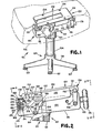
- the principles of the invention are disclosed, by way of example, in a chair tilt mechanism 100 depicted in Figure 1.
- the tilt mechanism 100 can be utilized with various types of chair assemblies, such as the assembly 101 also partially depicted in Figure 1.
- the chair assembly 101 includes a conventional chair seat 102 mounted above a seat casting 130 by means such as nut and bolt arrangements whereby the bolts are secured through bores 134 in the seat casting 130.
- the front of the chair assembly 101 is to the right and the rear is toward the left.
- the chair assembly 101 can have various types of back supports, arm rests and other conventional and well-known chair components. These components do not form the basis for any of the novel concepts of a chair tilt mechanism in accordance with the invention, and, accordingly, are not depicted in the drawings.
- the chair tilt mechanism 100 includes a lower support casting 110 having a downwardly depending cylindrical spindle housing 112.
- the housing 112 includes a central spindle bore 114 which can be threaded or otherwise include other conventional connecting means so as to receive a vertically disposed chair spindle 104 as depicted in Figure 1.
- the chair spindle 104 is conventionally secured at its lower end to a chair base 105 which can comprise any one of various and well-known chair-supporting arrangements.
- the chair base l05 can include several horizontally-extending support legs 106 having floor supports 107 mounted to the distal portions thereof.
- the support casting 110 is an integral casting which includes a slightly curved forward lower portion 116 and a slightly curved rear lower portion 118, each portion being integral with the spindle housing 112, which is positioned slightly rearward from the center of casting 110. Integrally connected to the forward lower portion 116 at the front thereof is a substantially vertical front portion 122 having a centrally located opening 179. Similarly, a rear vertical portion 120 is integrally connected to the rear lower portion 118.
- the casting 110 also includes a pair of upwardly extending side portions 124 integrally connected to the lateral sides of the forward lower portion 116 and rear lower portion 118.
- the aforedescribed components of casting 110 are configured so as to form a substantially tubular shaped shell 123, open at its top area.
- the support casting 110 thereby provides a means for securing the chair tilt mechanism 100 to the chair-supporting structure comprising the spindle 104 and chair base 105, and further provides a means for mounting various other components of the chair tilt mechanism 100 as subse - quently described herein.
- the chair tilt mechanism 100 includes a substantially horizontally disposed seat casting 130 having a forward cross portion 131 and a pair of parallel chair seat connecting brackets 132 integrally connected thereto and extending rearwardly from and in the same general plane as cross portion 131.
- the general shape and configuration of the seat casting 130 is depicted in Figure 1.
- the seat casting 130 includes vertically disposed bores 134 (four are depicted in Figure 1) which can be utilized with conventional connecting means to secure the tilt mechanism 100 to a chair seat such as seat 102 previously described.
- each side mounting 140 Integrally connected to the forward portion 131 and chair seat connecting brackets 132, and depending downwardly therefrom on each side of the adjustment mechanism 100, are a pair of side mountings 140, each side mounting having a forward upper hinge bracket 136.
- Each of the forward upper hinge brackets 136 is utilized to secure in a pivotable manner one of a pair of elongated forward links 150 which comprise a forward linkage means of tilt mechanism 100.
- the hinge brackets 136 each include a pair of parallel downwardly-depending flanges 137 having bores therethrough which receive an upper forward link pin 152.
- Link pin 152 is additionally received through a bore in the upper end of the forward link 150 so as to pivotably mount the link 150 intermediate the flanges 137.
- a retainer ring 154 is utilized to secure the link pin 152 within the bores of flanges 137.
- the mounting of links 150 to each of the upper hinge brackets 136 allows links 150 to freely rotate relative to an associated bracket, absent other mechanisms subsequently described herein which tend to maintain the position of links 150 relative to brackets 136 in a forward biased position depicted in Figure 2.
- each of the forward links 150 is pivotably secured to the forward area of one of the side portions 124 of support casting 110.
- the lower portion of each of the forward links 150 includes a smooth lateral bore concentrically positioned relative to threaded bore 158.
- conventional shoulder screw 156 is journalled into the smooth bore of each of links 150 so that the shoulder portion of screw 156 snugly mounts the link 150 but allows rotation thereof.
- the shoulder screws 156 are also threadably received in associated bores 158 and thereby provide a stationary transverse pivot axis for each of the links 150.
- the previously described arrangement of the forward link pins 150 comprises two linkages which form a forward linkage means of a four-bar linkage mechanism of chair tilt mechanism 100.
- the tilt mechanism 100 includes a pair of rear upper hinge brackets 138 integral with and depending downwardly from the chair connecting brackets 132 at the rear areas thereof as shown in Figures 2, 4 and 6.
- Each of the brackets 138 is utilized to secure in a pivotable manner one of a pair of rear links 160 comprising a rear linkage means of mechanism 100.
- the configuration of each of the rear links 160 is triangular in nature.
- the hinge brackets 138 each include a pair of parallel flanges 139 having smooth bores laterally therethrough which receive an upper rear link pin 162 similar to pin 152, and which pivotably secures the associated link 160 to the bracket 138.
- the pin 162 is further received through a smooth bore in the upper portion of link 160 so as to mount the pin 160 intermediate the bracket flanges 139.
- a retainer ring 154 is utilized to secure the link pin 162 within the bores of flanges 139.
- the pivotable mounting of rear links 160 to brackets 138 is substantially identical to the mounting of forward links 150 to brackets 136.
- each of the rear links 160 would be free to rotate within its mounting to a corresponding bracket 138 absent other mechanisms subsequently described herein which tend to maintain the relative position of brackets 138 and rear links 160 in the forward biased position depicted in Figure 2.
- each of the rear links 160 is pivotably secured to one of opposing sides 124 of support casting 110 by means of a conventional shoulder screw 164, similar to the previously described shoulder screw 156 utilized with links 150 but somewhat larger in size to accomodate the larger links 160.
- each shoulder screw 164 is journalled into a smooth bore of an associated link 160 so that its shoulder portion snugly mounts the link 160 but allows free rotation thereof.
- Each screw 164 is threaded at its end and received in a threaded bore 165 through the side portion 124 of support casting 110.
- the mounting of each link 160 to a corresponding shoulder screw 164 provides a stationary transverse pivot axis for the links 160.
- the lower curved portions 116, 118, rear and front vertical portions 120 and 122, respectively, and the side portions 124 of support casting 110 form a curved and partially enclosed shell 123 extending linearly through the tilt mechanism 100.
- a locator device 184 Connected to the front surface of rear vertical portion 120 is a locator device 184 shown in a partially cut-away section in Figure 2.
- the locator 184 is of a circular cross-section with a rear threaded bore centrally located and corresponding in diameter to a bore through the rear vertical portion 120.
- the locator 184 is rigidly secured to vertical portion 120 by conventional means such as flat head screw 182 threadably received in the above-described bores.
- Locator device 184 also includes a cylindrical socket 185 centrally located and extending partially through. the front portion of locator 184.
- an adjuster assembly 186 comprising integrally connected and substantially cylindrical outer, intermediate and inner collars 188, 190 and 192, respectively.
- the collars 188, 190 and 192 are consecutively stepped in diameter, with outer collar 188 having the largest diameter.
- a cylindrical recess 189 is centrally formed through the outer collar 188 and partially through the intermediate collar 190.
- the recess 189 is of a diameter sufficient in size to encapsulate the locator 184.
- a partially threaded shaft 178 Threadably received in bore 191 and extending longitudinally through the central area of shell 123 is a partially threaded shaft 178.
- the shaft 178 is of a length so that it is threaded completely through the threaded bore 191 and protrudes into the recess 189 of adjuster assembly 186 and into the socket 185 of locator 184.
- the spring yoke 210 is mounted within the front portion of shell 123 formed by support casting 110.
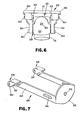
- the spring yoke 210 is depicted in Figure 7 apart from all other components of the tilt mechanism 100.
- the spring yoke 210 includes a front vertical portion 212 having a centrally located aperture 213.
- yoke 210 is mounted in shell 123 with the portion 212 facing towards the front vertical portion 122 of casting 110.
- the aperture 213 is positioned concentric with opening 179 and the shaft 178 is received through both aperture 213 and opening 179.
- the shaft 178 is also journalled into the adjustment knob 176.
- a bearing means such as nylon bearing 180, secures the shaft 178 within aperture 213 so that shaft 178 is free to rotate therewithin when the adjustment knob 176 is manually turned.
- the spring yoke 210 also includes a pair of side arms 214 integrally connected to and extending rearwardly from front vertical portion 212. Extending laterally through each of side arms 214 at the forward area thereof is a guide slot 216. Each side arm 214 terminates in an integrally connected yoke pivot bracket 218 angled outwardly and having bores 220 laterally extending through each of a pair of flanges 221.
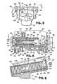
- FIG. 2 The positioning of the above-described elements of yoke 210 relative to other elements of mechanism 100 is depicted in Figures 2, 4 and 5.
- the side arms 214 of yoke 210 extend rearwardly within shell 123 adjacent the side portions 124 of support casting 110.
- Each of the pivot brackets 218 with associated flanges 221 extends outwardly from and above a recessed area of the side portions 124.
- the brackets 218 are utilized to pivotably mount an associated one of the triangularly shaped rear links 160.
- the flanges 221 of each of the brackets 218 are positioned on opposing sides of the rear link 160 so that a bore in link 160 is concentric with bores 220.
- a yoke pin 166 is received through bore 220 and secured by a means of a retainer ring 168.
- the rear link 160 is secured to spring yoke 210 in a manner so as to allow rotation of link 160 relative to an associated yoke pivot bracket 218.
- the yoke slot 216 is aligned with a bore 223 in a corresponding side portion 124 of casting 110.
- the relative alignment is such that the bore 223 is located near the rear of slot 216 when the front vertical portion 212 of yoke 210 is at its forwardmost biased position adjacent the front portion 122 of casting 110.
- a bearing means such as nylon bearing 225, is snugly fitted within slot 216.
- a grooved guide pin 227 is compression fitted within bearing 225 and journalled into bore 223 of side portion 124.
- slot 216, bore 223, bearing 225 and guide pin 227 are such that as yoke 210 and associated slots 216 are moved rearwardly, bearing 225 is free to slide within slot 216, but vertical movement of slot 216 relative to bore 223 is prohibited.
- the tilt mechanism 100 also includes an outer coiled spring 200 which extends longitudinally through shell 123.
- the front end of the spring 200 is compression fitted against the front vertical portion 212 of spring yoke 210.
- the opposing end of spring 200 is compression fitted against the outer collar 188 of adjuster assembly 186.
- the diameter of outer spring 200 relative to the diameter of intermediate collar 190 of assembly 186 provides a clamping of the rear coils of spring 200 around collar 190.
- the mechanism 100 also includes an inner spring 202 which is of a smaller diameter and shorter length than outer spring 200.
- the inner spring 202 extends longitudinally through shell 123.
- the rear end of inner spring 202 is compression fitted against a face of the intermediate collar 190 of adjuster assembly 186.
- the diameter of inner spring 202 relative to the diameter of inner collar 192 of adjuster assembly 186 provides a clamping of the rear coils of spring 202 around collar 192.
- the coils of the front opposing end of inner spring 202 are clamped around a small diameter section 193 of a cylindrical spring extender 194 having a bore therethrough which receives the threaded shaft 178.
- the spring extender 194 is snugly fitted to the shaft 178 but is free to move longitudinally therealong.
- the front and rear links 150 and 160 are located as shown in Figure 2.
- the chair seat 102 being rigidly connected to seat casting 130, is at a slight angle with its forward area above its rear area.
- Figures 4 and 5 depict various components mounted within shell 123 when mechanism 100 is in the forward biased position. Specifically, in the absence of externally applied tilting forces, there will be no forces applied to spring yoke 210 through its pivot connections to rear links 160 at yoke pins 166. Accordingly, the only forces applied to yoke 210 are forward directed biasing forces maintained by the compression of outer spring 188. The front vertical portion 212 of yoke 210 will thus be forced against the front vertical portion 122 of support casting 110. The forward directed forces will also be translated through yoke 210 and its pivot connections to rear links 160 through pins 166 to maintain the links 160 in the forward biased position shown in Figure 2.
- chair assembly 101 When the chair occupant desires to tilt the chair assembly 101 rearwardly, he will apply rearward "pushing" forces to the chair seat 102. An occupant can apply such forces directly to seat 102 through his legs by pushing his feet against the floor surface.
- chair assembly 101 can include a back support (not depicted) connected by various conventional means to seat 102. The occupant can then apply tilting forces to chair assembly 101 by pushing rearwardly against such a back support.
- the external forces applied to casting 130 will cause the casting 130 to pivot relative to rear links 160 through link pins 162.
- the casting 130 will impart forces to links 160 causing them to pivot about their lower stationary axis formed through their interconnections to support casting 110 through shoulder screws 164.
- the rear link 160 depicted therein will thus rotate counterclockwise about shoulder screw 164.
- outer spring 200 will result in reaction or biasing forces from spring 200 opposing the movement of yoke 210.
- the reaction forces increase as the yoke 210 moves away from its forward biased position, thereby requiring the occupant to exert correspondingly increasing tilting forces to tilt the chair assembly 101 farther and farther away from equilibrium. If the exertion of tilting forces ceases, the biasing forces of spring 200 will push the yoke 210 forward and return all components of mechanism 100 to the forward biased position.
- the central axis of tilting rotation of seat casting 130 is best described by first defining the two planes A and B depicted in Figures 8 and 9.
- An upper pivot axis of the two rear links 160 relative to seat casting 130 can be defined by a line axially through the centers of the two colinear upper rear link pins 162.
- a stationary lower pivot axis of rear links 160 relative to support casting 100 can be defined by a line axially through the centers of the two shoulder screws 164.
- These upper and lower pivot axes will be parallel, and the plane A can be defined as including the lower pivot axis and bisecting the arc travelled by the upper pivot axis between the initial forward biased position and the fully tilted position.
- an upper pivot axis of the two forward links 150 relative to seat casting 130 can be defined by a line extending axially through the centers of the two colinear upper forward link pins 152.
- a stationary lower pivot axis of forward links 150 relative to support casting 110 can be defined by a line extending axially through the centers of the two shoulder screws 156.
- plane B can be defined as including the lower pivot axis and bisecting the arc travelled by the upper pivot axis between the initial forward biased position and the fully tilted position of forward links 150.
- the four-bar linkage comprising links 150, 160 transposes the rotational axis of the seat casting 130 a distance away so as to provide a gradual tilting movement, as opposed to an abrupt angular rotation relative to a pivot at or near the casting 130.
- the transposed axis of rotation is defined by the line formed at the intersection of planes A and B. Although this axis is not specifically depicted in Figures 8 and 9, it is apparent from the relative relationship of planes A and B that the axis will be located near the chair occupant's ankles. Accordingly, the tilting motion will be more natural to the occupant than motion whereby the rotational axis is above the seat casting 130 or otherwise located a substantial distance away from the occupant's ankle position.
- the front vertical portion 212 of yoke 210 will compress outer spring 200, thereby causing the spring 200 to impart a reactive or biasing force against yoke 210 at a first force rate.
- the front vertical portion of yoke 210 will contact the forward end of spring extender 194. Further movement of seat casting 130, i.e. through a second angle beyond the first angle until the fully tilted position is achieved, will cause yoke 210 to compress not only outer spring 200 but also inner spring 202.
- both springs 200, 202 will impart a reactive or biasing force of a second force rate greater than the first force rate.
- the magnitude of the first predetermined angle will be dependent in part on the distance between the extender 194 and portion 212 of yoke 210 when the mechanism 100 is in the forward biased position.
- a chair tilting mechanism have means for adjusting the tension of the tilting mechanism, i.e. a means for adjusting the amount of externally applied tilting forces required to tilt a chair prescribed distances away from the forward biased position. It is also preferable to have a substantial range of such tension settings so as to accomodate both small and large individuals. For large individuals, the opposing forces exerted by the tilting mechanism should be relatively high. Conversely, a small individual is uncomfortable if he or she must overcome large opposing forces in order to tilt a chair to a desired position.
- the chair tilt mechanism 100 provides a means for adjusting the biasing or opposing reactive forces to externally applied tilting forces over a substantially wide range.
- the occupant can adjust the compressed length of outer spring 200 when the spring 200 is in the initial forward biased position.
- the rear end of the outer spring 200 abuts the surface of outer collar 188 of adjuster assembly 186.
- the front end of spring 200 abuts the vertical front portion 212 of spring yoke 210.
- the adjustment knob 176 By rotating the adjustment knob 176, the occupant can adjust the threaded distance of shaft 178 within the adjuster assembly 186.
- the opposing forces exerted by spring 200 on yoke 210 can be adjust- ably increased or decreased for a given tilted position of the chair tilt mechanism 100.
- the adjustment arrangement heretofore described will not disturb the forward biased position. That is, the seat casting 130 will be maintained at one particular forward biased position regardless of the adjustment of the initial compressed length of outer spring 200.
- knob 176 adjustment by means of knob 176 will cause the distance between portion 212 of yoke 210 and the extender 194 to be selectively increased or decreased. Accordingly, for particularly heavy individuals, the portion 212 of yoke 210 can be made to contact extender 194 or even to compress inner spring 202 when the mechanism 100 is in the forward biased position. In such event, the occupant will be required to overcome biasing forces of both springs 200 and 202 througout movement of seat casting 130 from the forward biased to the fully tilted position.
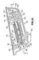
- a support casting 300 has a spindle housing 302, a bottom wall 304, a front wall 306, a back wall 308 and side walls 310.
- a stop member 312 is formed from a web within the back of the casting.
- a front web 360 is formed at the front portion of the casting and has a vertical slot 362 and bores 372.
- the stop member 312 has a slot 313 formed in a central portion thereof.
- a seat casting 314 has a forward hinge bracket 316 and a rear hinge bracket 318.
- a forward link 320 is secured at one end to the seat casting 314 through a pin 322 and at the other end to the support casting 300 through a pin 324.
- a rear link 326 is secured at one end to the support casting 300 through a pin 328 and at the other end to the seat casting 314 through a pin 330.
- a front spring retainer 332 has a pair of forwardly- projecting ears 333 through which it is pivotably coupled to the forward link 320 through a pair of pins 334.
- a large spring 336 is seated against a flat face of the front spring retainer 332 at one end and is seated against a rear spring retainer 338 at the other end.
- the rear spring retainer 338 has a forward annular projection 340.
- a small spring 342 is seated at one end against the forward projection 340 of the rear spring retainer 338 and projects forwardly to a point short of the front spring retainer 332.
- An adjustment shaft 344 extends through the small spring 342 and has a threaded end 346 which is threaded into a tapped hole 348 of the rear spring retainer 338.
- the adjustment shaft 344 has a reduced-diameter journal end 350 which fits within the slot 313 of the stop member 312.
- a retainer plate 358 is secured to the stop member 312 through screws (not shown) to retain the journal end 350 of the adjustment shaft 344.
- Thrust washers 352 are positioned on the end of the adjustment shaft 344 and bear against the stop member 312 to firmly seat the shaft 344 thereagainst.
- the forward end of the adjustment shaft 344 is journaled in the slot 362 in the front web 360.
- a retainer plate 364 is secured to the top of the front web 360 through screws (not shown) over the slot 362 to retain the adjustment shaft 344 within the slot 362.
- the adjustment shaft 344 is also slidably received within an opening 354 of the front spring retainer 332.
- a bevel gear 356 is secured to the forwardmost portion of the adjustment shaft 344.
- a tension-adjusting shaft 368 having a handle 370 on the end thereof extends into the support casting 300 from the outside thereof and is journaled in the bores 372 of the front web 360.
- a bevel gear 366 is secured nonrotatably to the shaft 368 and meshes with the bevel gear 356.
- the seat casting 314 In operation, as the seat casting 314 is pushed rearwardly with respect to the support casting 300, the seat casting 314 will pivot about a pivot axis near the ankle of the user. To this end, the links 326 will pivot about the pins 328 and the links 320 will pivot about the pins 324. As this pivot action takes place, the front links 320 drive the front spring retainer 332 rearwardly (or to the left as illustrated in Figure 10), thereby compressing the large spring 336. If the seat casting 314 is rotated far enough, the front spring retainer 332 will eventually contact and begin compressing the small spring 342. When the small spring 342 is compressed, a much higher spring rate will be experienced.
- the point at which the small spring 342 becomes activated can be adjusted by rotating the tension-adjusting shaft 368. Rotation of the shaft 368 will result in a corresponding rotation of the adjustment shaft 344 which, in turn, will cause the rear spring retainer 338 to move along the shaft 344 due to the threaded connection between shaft 344 and the rear spring retainer 338.
- the rear spring retainer 338 As the rear spring retainer 338 is moved along the shaft 344 to the right as seen in Figure 10, it compresses the large spring 336 and also moves the small spring 342 closer to the front spring retainer 332.
- the closer the small spring 342 is to the front spring retainer 332 the sooner the small spring 342 is effective during the tilting angle of the seat casting 314 with respect to the support casting 300. Movement of the rear spring retainer in an opposite direction will have an opposite effect on the point at which the small spring is effective.
Landscapes
- Chairs Characterized By Structure (AREA)
Applications Claiming Priority (2)
| Application Number | Priority Date | Filing Date | Title |
|---|---|---|---|
| US06/570,076 US4652050A (en) | 1984-01-11 | 1984-01-11 | Chair tilt mechanism |
| US570076 | 1984-01-11 |
Publications (3)
| Publication Number | Publication Date |
|---|---|
| EP0149041A2 true EP0149041A2 (fr) | 1985-07-24 |
| EP0149041A3 EP0149041A3 (en) | 1986-05-07 |
| EP0149041B1 EP0149041B1 (fr) | 1989-07-12 |
Family
ID=24278116
Family Applications (1)
| Application Number | Title | Priority Date | Filing Date |
|---|---|---|---|
| EP84113440A Expired EP0149041B1 (fr) | 1984-01-11 | 1984-11-07 | Mécanisme pour chaise inclinable |
Country Status (4)
| Country | Link |
|---|---|
| US (1) | US4652050A (fr) |
| EP (1) | EP0149041B1 (fr) |
| CA (1) | CA1225321A (fr) |
| DE (1) | DE3478894D1 (fr) |
Cited By (4)
| Publication number | Priority date | Publication date | Assignee | Title |
|---|---|---|---|---|
| EP0281256A1 (fr) * | 1987-02-09 | 1988-09-07 | Haworth, Inc. | Mécanisme de basculement pour chaise sur colonne |
| EP0303996A3 (en) * | 1987-08-20 | 1989-06-28 | Klober Gmbh & Co. | Working-chair with a tiltable seat |
| WO1991001663A1 (fr) * | 1989-08-04 | 1991-02-21 | Kairos S.R.L. | Support pour l'assise de fauteuils ou similaires a inclinaison automatique |
| EP3505013A1 (fr) * | 2018-01-02 | 2019-07-03 | Dongguan Kentec Office Seating Co., Ltd | Dispositif de support souple pour dossier de fauteuil inclinable |
Families Citing this family (35)
| Publication number | Priority date | Publication date | Assignee | Title |
|---|---|---|---|---|
| US4709963A (en) * | 1986-12-12 | 1987-12-01 | Milsco Manufacturing Company | Adjustable office chair |
| US4818019A (en) * | 1987-02-09 | 1989-04-04 | Haworth, Inc. | Tilt control mechanism, particularly for knee-tilt chair |
| US4979778A (en) * | 1989-01-17 | 1990-12-25 | Brayton International, Inc. | Synchrotilt chair |
| US5106157A (en) * | 1989-03-01 | 1992-04-21 | Herman Miller, Inc. | Chair height and tilt adjustment mechanisms |
| US5029940A (en) * | 1990-01-16 | 1991-07-09 | Westinghouse Electric Corporation | Chair tilt and chair height control apparatus |
| EP0485868A1 (fr) * | 1990-11-14 | 1992-05-20 | Giroflex-Entwicklungs AG | Chaise, en particulier chaise d'office |
| US5577807A (en) * | 1994-06-09 | 1996-11-26 | Steelcase Inc. | Adjustable chair actuator |
| CA2310349A1 (fr) * | 2000-05-22 | 2001-11-22 | Todd D. Krupiczewicz | Fauteuil de bureau |
| AU783829B2 (en) | 2000-09-28 | 2005-12-08 | Formway Furniture Limited | A reclinable chair |
| US6585320B2 (en) | 2001-06-15 | 2003-07-01 | Virco Mgmt. Corporation | Tilt control mechanism for a tilt back chair |
| US20030132653A1 (en) * | 2001-10-18 | 2003-07-17 | Doug Thole | Tension control mechanism for a chair |
| ITMI20030238A1 (it) * | 2003-02-11 | 2004-08-12 | Donati Spa | Metodo e meccanismo per la realizzazione di sedie o poltroncine per ufficio |
| DE10309920A1 (de) * | 2003-03-07 | 2004-09-16 | Dauphin Entwicklungs- Und Beteiligungs-Gmbh | Stuhl, insbesondere Bürostuhl |
| ITVE20030014A1 (it) * | 2003-04-10 | 2004-10-11 | Imarc Spa | Dispositivo di regolazione del grado di precarica delle molle in meccanismi di sedie da ufficio. |
| US7566099B2 (en) * | 2003-10-22 | 2009-07-28 | Lord Corporation | Furniture seatback tilt recline angle limiter and method |
| US7500718B2 (en) * | 2004-05-14 | 2009-03-10 | Haworth, Inc. | Tilt tension mechanism for chair |
| ITMI20070719A1 (it) * | 2007-04-06 | 2008-10-07 | L & P Property Management Co | Dispositivo di inclinazione per un sedile reclinabile. |
| ITMI20070718A1 (it) * | 2007-04-06 | 2008-10-07 | L & P Property Management Co | Dispositivo di regolazione per sedie regolabili e simili. |
| WO2009134451A1 (fr) | 2008-05-02 | 2009-11-05 | Haworth, Inc. | Mécanisme de tension pour une chaise sensible au poids |
| US7681952B2 (en) * | 2008-06-06 | 2010-03-23 | Pro-Cord S.P.A. | Chair with tiltable backrest |
| USD697726S1 (en) | 2012-09-20 | 2014-01-21 | Steelcase Inc. | Chair |
| US11304528B2 (en) | 2012-09-20 | 2022-04-19 | Steelcase Inc. | Chair assembly with upholstery covering |
| US9839292B2 (en) | 2014-04-08 | 2017-12-12 | John Hart Miller | Rotating and non-rotating reclining chairs w/tilting mechanisms |
| US9883748B2 (en) | 2015-05-15 | 2018-02-06 | Knoll, Inc. | Training device for a seating device and method of using the same |
| US9585485B2 (en) | 2015-05-15 | 2017-03-07 | Knoll, Inc. | Seating device having a tilt mechanism |
| US10021979B2 (en) | 2016-02-22 | 2018-07-17 | John Hart Miller | Rotating and non-rotating reclining chairs with tilting mechanisms |
| GB2551737B (en) * | 2016-06-28 | 2019-06-05 | Posturite Ltd | Seat tilting mechanism with two springs |
| US10194749B1 (en) | 2017-05-23 | 2019-02-05 | Yeti Coolers, Llc | Portable chair and methods of forming a portable chair |
| US10561249B2 (en) | 2017-05-23 | 2020-02-18 | Yeti Coolers, Llc | Portable chair and cup holder assembly |
| US10743670B2 (en) | 2017-05-23 | 2020-08-18 | Yeti Coolers, Llc | Portable chair and cup holder assembly |
| CN107898197B (zh) * | 2017-09-22 | 2020-09-11 | 东莞致诚办公家具有限公司 | 具有同步调整结构的座椅 |
| USD843151S1 (en) | 2018-01-10 | 2019-03-19 | Yeti Coolers, Llc | Portable chair |
| USD843150S1 (en) | 2018-01-10 | 2019-03-19 | Yeti Coolers, Llc | Portable chair |
| USD843152S1 (en) | 2018-01-10 | 2019-03-19 | Yeti Coolers, Llc | Portable chair |
| USD850810S1 (en) | 2018-01-10 | 2019-06-11 | Yeti Coolers, Llc | Portable chair |
Family Cites Families (22)
| Publication number | Priority date | Publication date | Assignee | Title |
|---|---|---|---|---|
| US2028633A (en) * | 1933-02-10 | 1936-01-21 | Quicktho 1928 Ltd | Seat |
| US2374350A (en) * | 1941-10-01 | 1945-04-24 | Bassick Co | Posture chair |
| US2341124A (en) * | 1942-05-22 | 1944-02-08 | Collier Keyworth Company | Chair iron |
| US2516801A (en) * | 1944-03-16 | 1950-07-25 | Harold E Renaud | Chair having spring supported seat |
| US2463257A (en) * | 1947-06-25 | 1949-03-01 | Seng Co | Resilient mounting means for tilting chairs |
| US2650646A (en) * | 1949-08-23 | 1953-09-01 | Bassick Co | Resiliently mounted tiltable seat and back rest |
| NL68714C (fr) * | 1950-02-22 | 1951-09-15 | ||
| US2830650A (en) * | 1953-10-23 | 1958-04-15 | Lorenz Anton | Article of repose for supporting the body of a person |
| US2859799A (en) * | 1956-05-03 | 1958-11-11 | Edwin R Moore | Functional posture controller for chairs |
| US2859801A (en) * | 1956-09-17 | 1958-11-11 | Edwin R Moore | Geometric controller for chairs |
| US3037735A (en) * | 1958-10-13 | 1962-06-05 | Gen Motors Corp | Trackless six-way seat adjuster |
| DE1505314A1 (de) * | 1965-06-09 | 1970-04-23 | Nordpatent Ab | Federndes Untergestell fuer Fahrzeugsitze |
| US3333811A (en) * | 1965-09-07 | 1967-08-01 | Wil Mat Corp | Rocker mechanism |
| US3417956A (en) * | 1966-08-02 | 1968-12-24 | Art Metal Knoll Corp | Chair control |
| GB1203783A (en) * | 1967-05-03 | 1970-09-03 | G K N Sankey Ltd Formerly Jose | Improvements in or relating to chairs having hinged backrests |
| US3453024A (en) * | 1967-11-06 | 1969-07-01 | Stewart Warner Corp | Single action chair control |
| US3741607A (en) * | 1970-10-05 | 1973-06-26 | H Cramer | Chair |
| GB1451088A (en) * | 1973-12-10 | 1976-09-29 | Vinten Ltd | Tilt mounting heads |
| US4209158A (en) * | 1978-02-15 | 1980-06-24 | Ferro Manufacturing Corporation | Seat adjuster |
| GB2020968B (en) * | 1979-03-12 | 1982-07-07 | Uop Inc | Vehicle seats |
| US4429917A (en) * | 1981-04-29 | 1984-02-07 | Hauserman Inc. Int. Furniture & Textile Division | Chair |
| US4479679A (en) * | 1981-06-08 | 1984-10-30 | Steelcase Inc. | Body weight chair control |
-
1984
- 1984-01-11 US US06/570,076 patent/US4652050A/en not_active Expired - Lifetime
- 1984-10-16 CA CA000465554A patent/CA1225321A/fr not_active Expired
- 1984-11-07 EP EP84113440A patent/EP0149041B1/fr not_active Expired
- 1984-11-07 DE DE8484113440T patent/DE3478894D1/de not_active Expired
Cited By (4)
| Publication number | Priority date | Publication date | Assignee | Title |
|---|---|---|---|---|
| EP0281256A1 (fr) * | 1987-02-09 | 1988-09-07 | Haworth, Inc. | Mécanisme de basculement pour chaise sur colonne |
| EP0303996A3 (en) * | 1987-08-20 | 1989-06-28 | Klober Gmbh & Co. | Working-chair with a tiltable seat |
| WO1991001663A1 (fr) * | 1989-08-04 | 1991-02-21 | Kairos S.R.L. | Support pour l'assise de fauteuils ou similaires a inclinaison automatique |
| EP3505013A1 (fr) * | 2018-01-02 | 2019-07-03 | Dongguan Kentec Office Seating Co., Ltd | Dispositif de support souple pour dossier de fauteuil inclinable |
Also Published As
| Publication number | Publication date |
|---|---|
| US4652050A (en) | 1987-03-24 |
| DE3478894D1 (en) | 1989-08-17 |
| CA1225321A (fr) | 1987-08-11 |
| EP0149041A3 (en) | 1986-05-07 |
| EP0149041B1 (fr) | 1989-07-12 |
Similar Documents
| Publication | Publication Date | Title |
|---|---|---|
| US4652050A (en) | Chair tilt mechanism | |
| US4830431A (en) | Interlocking cushioning mechanism for supporting seat portion and backrest of chair in integral fashion | |
| EP0722283B1 (fr) | Chaise a dossier scinde | |
| US7281764B2 (en) | Tension control mechanism for chair | |
| US4962962A (en) | Piece of seating furniture | |
| JP2505458B2 (ja) | ガス圧ばねを備えた高さ調節可能な回転椅子 | |
| US5192114A (en) | Tilt adjustment control for a chair | |
| CA1238569A (fr) | Meuble-siege | |
| US5931531A (en) | Chair having adjustable synchronous tilting | |
| FI104615B (fi) | Järjestely nojatuoliin, jossa on säädettävä selkänoja | |
| US4756575A (en) | Frame assembly for a chair | |
| US20030071502A1 (en) | Leaf spring rocker mechanism for a reclining chair | |
| EP0283170B1 (fr) | Chaises à colonne | |
| EP0063860A2 (fr) | Chaise | |
| US5033791A (en) | Chair frame | |
| US4906045A (en) | Chair control for a pedestal chair having a knee-tilt seat | |
| US4718726A (en) | Chair seat tilt control | |
| US4013257A (en) | Chair control | |
| US4438978A (en) | Tilt back mechanism for a chair | |
| US3455601A (en) | Support unit for chair | |
| JPH0355321Y2 (fr) | ||
| US4718725A (en) | Support-and adjusting device for seat and backrest on a work chair | |
| JP3046348B2 (ja) | トーションばねを用いた椅子のためのトーションばねおよび調整式取付機構 | |
| JP2797273B2 (ja) | 背もたれ付き椅子 | |
| GB2193886A (en) | Improved invalid chair |
Legal Events
| Date | Code | Title | Description |
|---|---|---|---|
| PUAI | Public reference made under article 153(3) epc to a published international application that has entered the european phase |
Free format text: ORIGINAL CODE: 0009012 |
|
| AK | Designated contracting states |
Designated state(s): AT BE CH DE FR GB IT LI LU NL SE |
|
| RBV | Designated contracting states (corrected) |
Designated state(s): DE FR GB |
|
| PUAL | Search report despatched |
Free format text: ORIGINAL CODE: 0009013 |
|
| AK | Designated contracting states |
Kind code of ref document: A3 Designated state(s): DE FR GB |
|
| 17P | Request for examination filed |
Effective date: 19860926 |
|
| 17Q | First examination report despatched |
Effective date: 19880525 |
|
| GRAA | (expected) grant |
Free format text: ORIGINAL CODE: 0009210 |
|
| AK | Designated contracting states |
Kind code of ref document: B1 Designated state(s): DE FR GB |
|
| REF | Corresponds to: |
Ref document number: 3478894 Country of ref document: DE Date of ref document: 19890817 |
|
| ET | Fr: translation filed | ||
| PLBE | No opposition filed within time limit |
Free format text: ORIGINAL CODE: 0009261 |
|
| STAA | Information on the status of an ep patent application or granted ep patent |
Free format text: STATUS: NO OPPOSITION FILED WITHIN TIME LIMIT |
|
| 26N | No opposition filed | ||
| PGFP | Annual fee paid to national office [announced via postgrant information from national office to epo] |
Ref country code: FR Payment date: 20000920 Year of fee payment: 17 |
|
| PGFP | Annual fee paid to national office [announced via postgrant information from national office to epo] |
Ref country code: GB Payment date: 20001025 Year of fee payment: 17 |
|
| PGFP | Annual fee paid to national office [announced via postgrant information from national office to epo] |
Ref country code: DE Payment date: 20001228 Year of fee payment: 17 |
|
| PG25 | Lapsed in a contracting state [announced via postgrant information from national office to epo] |
Ref country code: GB Free format text: LAPSE BECAUSE OF NON-PAYMENT OF DUE FEES Effective date: 20011107 |
|
| REG | Reference to a national code |
Ref country code: GB Ref legal event code: IF02 |
|
| GBPC | Gb: european patent ceased through non-payment of renewal fee |
Effective date: 20011107 |
|
| PG25 | Lapsed in a contracting state [announced via postgrant information from national office to epo] |
Ref country code: DE Free format text: LAPSE BECAUSE OF NON-PAYMENT OF DUE FEES Effective date: 20020702 |
|
| PG25 | Lapsed in a contracting state [announced via postgrant information from national office to epo] |
Ref country code: FR Free format text: LAPSE BECAUSE OF NON-PAYMENT OF DUE FEES Effective date: 20020730 |
|
| REG | Reference to a national code |
Ref country code: FR Ref legal event code: ST |
|
| REG | Reference to a national code |
Ref country code: FR Ref legal event code: ST |