EP0149059A2 - Griffbügel für Transportroller - Google Patents
Griffbügel für Transportroller Download PDFInfo
- Publication number
- EP0149059A2 EP0149059A2 EP84114081A EP84114081A EP0149059A2 EP 0149059 A2 EP0149059 A2 EP 0149059A2 EP 84114081 A EP84114081 A EP 84114081A EP 84114081 A EP84114081 A EP 84114081A EP 0149059 A2 EP0149059 A2 EP 0149059A2
- Authority
- EP
- European Patent Office
- Prior art keywords
- handle
- bends
- handle bar
- designed
- pipe bend
- Prior art date
- Legal status (The legal status is an assumption and is not a legal conclusion. Google has not performed a legal analysis and makes no representation as to the accuracy of the status listed.)
- Granted
Links
Images
Classifications
-
- B—PERFORMING OPERATIONS; TRANSPORTING
- B62—LAND VEHICLES FOR TRAVELLING OTHERWISE THAN ON RAILS
- B62B—HAND-PROPELLED VEHICLES, e.g. HAND CARTS OR PERAMBULATORS; SLEDGES
- B62B5/00—Accessories or details specially adapted for hand carts
- B62B5/06—Hand moving equipment, e.g. handle bars
Definitions
- the invention relates to a handle bar for a transport roller according to the preamble of claim 1.
- the handle which surrounds the tube formed into a handle, consists of two handle halves, which are connected by a film hinge on one long side and held together on the other long side by a snap-in connection.
- a disadvantage of this handle is that due to the connection of the two handle halves via a film hinge, it can only be used or attached to approximately straight pipe sections. There is also a parting line that rubs against the palm of the hand when the transport roller is pulled.
- the object of the invention is to provide a handle bar for a transport roller that lies optimally in the hand, can also be used for round pipe bends and can be easily manufactured and assembled.
- the far down sidewalls offer a further improvement in comfort.
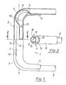
- a handle 1 of a transport roller essentially consists of a U-shaped tube with a pipe bend 3 to which a handle 4 is attached.
- the pipe bend 3 is formed by two American bends 5 and a center piece 6.
- the American bends 5 are characterized by an approximately central indentation 7. This indentation 7 results in two side walls 8, between which an elevation 9 engages on the inside 10 of the handle.
- the handle 4 which is designed as a handle, is open to the outside and provided with side cheeks 11.
- the side cheeks 11 lie against the tube 2 under prestress.
- spacer webs 13 are arranged in the handle, which are adapted approximately to the pipe contour.
- the side walls 12 are raised slightly above the center line 14 of the center piece 6.
- the grip is also carried out in the area of the center line 14 with an inner radius 15 which corresponds to the outside radius of the center piece 6, so that an undercut is produced in the area 16, which also has a clamping effect.
- the handle is held both on the side cheeks 11 and the undercut in the area 16 on the pipe bend 3.
Landscapes
- Engineering & Computer Science (AREA)
- Chemical & Material Sciences (AREA)
- Combustion & Propulsion (AREA)
- Transportation (AREA)
- Mechanical Engineering (AREA)
- Handcart (AREA)
- Steering Devices For Bicycles And Motorcycles (AREA)
- Details Of Rigid Or Semi-Rigid Containers (AREA)
- Passenger Equipment (AREA)
- Automatic Cycles, And Cycles In General (AREA)
Abstract
Description
- Die Erfindung bezieht sich auf einen Griffbügel für einen Transportroller gemäß dem Oberbegriff des Anspruchs 1.
- Nach dem DE-GM 74 23 156 ist ein derartiger Griffbügel bekannt. Der das zum Griffbügel geformte Rohr umschließende Handgriff besteht aus zwei Griffhälften, die über ein FiLmscharnier an der einen Längsseite verbunden sind und an der anderen Längsseite über eine einrastende Verbindung zusammengehalten werden. Nachteilig an diesem Handgriff ist, daß er bedingt durch die Verbindung der beiden GriffhäLften über ein FiLmscharnier nur bei annähernd geraden Rohrstücken anwendbar, beziehungsweise befestigbar ist. Des weiteren entsteht eine Trennfuge, die beim Ziehen des Transportrollers an der HandfLäche reibt.
- Aufgabe der Erfindung ist es, einen Griffbügel für einen TransportroLLer zu schaffen, der optimal in der Hand Liegt, auch für runde Rohrbogen anwendbar ist und Leicht gefertigt und montiert werden kann.
- Diese Aufgabe wird durch die kennzeichnenden MerkmaLe des Anspruchs 1 gelöst. Dadurch,daß der Handgriff von der Innenseite auf den Rohrbogen aufgeklemmt ist, entsteht eine im Bereich der AufLage an der HandfLäche geschlossene GriffschaLe. Es gibt keine störenden TrennsteLLen. Der Handgriff ist gleichermaßen gut bei runden wie gestreckten Rohrbögen anzubringen. Er ist preiswert herzusteLLen und Leicht zu montieren.
- Weitere AusgestaLtungen der Erfindung sind den Unteransprüchen zu entnehmen. So kann bei AusbiLdung des Rohrbogens über zwei sogenannte amerikanische Biegungen ein besonders schmaler GriffbügeL verwirklicht werden, der nur unwesentlich breiter aLs eine Hand ist, wodurch eine besonders gute Führung des Transportrollers mögLich wird. Durch die amerikanischen Biegungen entstehen automatisch Eindrückungen im Rohrbogen, die eine einfache Verrastung des Handgriffs ermöglichen. Die Verrastungsstege der inneren GriffschaLe können gleichzeitig aLs Distanzstege genutzt werden, um optisch einen füLLigeren Handgriff zu verwirklichen.
- Die weit heruntergezogenen Seitenwangen bieten eine weitere Komfortverbesserung.
- Ein AusführungsbeispieL der Erfindung wird im folgenden an Hand der Zeichnungen dargesteLLt.
- Es zeigen:
- Figur 1 eine Ansicht auf einen GriffbügeL eines Transportrollers, wobei die eine HäLfte im Schnitt, die andere HäLfte in der Draufsicht dargestellt ist und
- Figur 2 einen Schnitt gemäß der Linie II - II in Figur 1.
- Ein Griffbügel 1 eines Transportrollers besteht im wesentlichen aus einem U-förmig gebogenen Rohr mit einem Rohrbogen 3 an dem ein Handgriff 4 befestigt ist. Der Rohrbogen 3 wird durch zwei amerikanische Biegungen 5 und einem MitteLstück 6 gebildet. Die amerikanischen Biegungen 5 sind durch eine annähernd zentrische Eindrückung 7 gekennzeichnet. Durch diese Eindrückung 7 entstehen jeweils zwei Seitenwände 8, zwischen die eine Erhebung 9 auf der Innenseite 10 des Handgriffs eingreift.
- Der Handgriff 4, der aLs GriffschaLe ausgebildet ist, ist zur Außenseite offen und mit Seitenwangen 11 versehen. Die Seitenwangen 11 Liegen unter Vorspannung am Rohr 2 an.
- Um aus ergonomischen Gründen höhere Seitenwände 12 zu erreichen, sind in der GriffschaLe Distanzstege 13 angeordnet, die in etwa der Rohrkontur angepaßt sind. Die Seitenwände 12 sind etwas über die MitteLLinie 14 des MitteLstücks 6 hochgezogen. Die GriffschaLe ist weiter im Bereich der MitteLLinie 14 mit einem Innenradius 15, der dem Außenradius des MitteLstücks 6 entspricht ausgeführt, so daß im Bereich 16 ein Hinterschnitt entsteht, der zusätzlich klemmend wirkt. Dadurch wird der Handgriff sowohl über die Seitenwangen 11 als auch den Hinterschnitt im Bereich 16 am Rohrbogen 3 gehalten.
Claims (5)
Priority Applications (1)
| Application Number | Priority Date | Filing Date | Title |
|---|---|---|---|
| AT84114081T ATE38188T1 (de) | 1983-12-27 | 1984-11-22 | Griffbuegel fuer transportroller. |
Applications Claiming Priority (2)
| Application Number | Priority Date | Filing Date | Title |
|---|---|---|---|
| DE3347159A DE3347159C2 (de) | 1983-12-27 | 1983-12-27 | Griffbügel für Transportroller |
| DE3347159 | 1983-12-27 |
Publications (3)
| Publication Number | Publication Date |
|---|---|
| EP0149059A2 true EP0149059A2 (de) | 1985-07-24 |
| EP0149059A3 EP0149059A3 (en) | 1987-04-29 |
| EP0149059B1 EP0149059B1 (de) | 1988-10-26 |
Family
ID=6218206
Family Applications (1)
| Application Number | Title | Priority Date | Filing Date |
|---|---|---|---|
| EP84114081A Expired EP0149059B1 (de) | 1983-12-27 | 1984-11-22 | Griffbügel für Transportroller |
Country Status (4)
| Country | Link |
|---|---|
| EP (1) | EP0149059B1 (de) |
| AT (1) | ATE38188T1 (de) |
| DE (1) | DE3347159C2 (de) |
| ES (1) | ES295024Y (de) |
Family Cites Families (4)
| Publication number | Priority date | Publication date | Assignee | Title |
|---|---|---|---|---|
| DE7423156U (de) * | 1974-11-28 | Gebrueder Schulte | Aus Kunststoff bestehender Handgriff für Einkaufsroiler | |
| CH598878A5 (en) * | 1975-08-14 | 1978-05-12 | Stoecklin Walter Ag | Bending machine for ribbed circular sections |
| DE7637653U1 (de) * | 1976-12-01 | 1977-03-17 | Franz Kahl Kg, 6000 Frankfurt | Fuehrungsgriff, insbesondere fuer gabelhubwagen |
| DE7822257U1 (de) * | 1978-07-25 | 1979-04-12 | Repa Feinstanzwerk Gmbh, 7071 Alfdorf | Umlenkbeschlag fuer einen sicherheitsgurt |
-
1983
- 1983-12-27 DE DE3347159A patent/DE3347159C2/de not_active Expired
-
1984
- 1984-11-22 AT AT84114081T patent/ATE38188T1/de not_active IP Right Cessation
- 1984-11-22 EP EP84114081A patent/EP0149059B1/de not_active Expired
- 1984-12-26 ES ES1984295024U patent/ES295024Y/es not_active Expired
Also Published As
| Publication number | Publication date |
|---|---|
| ATE38188T1 (de) | 1988-11-15 |
| ES295024Y (es) | 1987-07-16 |
| EP0149059B1 (de) | 1988-10-26 |
| DE3347159C2 (de) | 1985-11-14 |
| EP0149059A3 (en) | 1987-04-29 |
| ES295024U (es) | 1986-11-01 |
| DE3347159A1 (de) | 1985-07-18 |
Similar Documents
| Publication | Publication Date | Title |
|---|---|---|
| DE3302391C2 (de) | ||
| DE60210263T2 (de) | Nagelschere | |
| EP2821555B1 (de) | Wasserauslaufarmatur mit flexibler Auslaufführung | |
| DE9004761U1 (de) | Rasierapparatekopf, insbesondere Rasierklingeneinheit, eines Naßrasierapparates | |
| DE1680066B2 (de) | Schiebedachkonstruktion für Kraftfahrzeuge | |
| EP0413143A1 (de) | Rasierapparatekopf, insbesondere Rasierklingeneinheit eines Nassrasierapparates | |
| DE29801166U1 (de) | Positionierhilfe für einen Wasserauslaß-Schlauch eines Wasserbehälters | |
| DE8914582U1 (de) | Wundklammer, insbesondere chirurgischer Mikroclip | |
| EP0308958A2 (de) | Energieführungskette | |
| EP0560239A1 (de) | Rasierapparatekopf eines Nassrasierapparates | |
| EP0453717B1 (de) | Rasierapparatekopf, insbesondere Rasierklingeneinheit, eines Nassrasierapparates | |
| EP0149059A2 (de) | Griffbügel für Transportroller | |
| DE20114744U1 (de) | Trägervorrichtung für Reinigungsbezüge | |
| EP1333962A1 (de) | Schneidevorrichtung mit zwei durch handgriffbetätigung aufeinanderzubewegbaren backen | |
| DE3104159A1 (de) | Vorrichtung zum bilden eines abzweigstueckes an einem rohr | |
| EP1428941B1 (de) | Anordnung zur Anbringung eines Sanitärgegenstands | |
| EP0655544A1 (de) | Sprossenkreuz | |
| DE9416529U1 (de) | Abgewinkelter Eckverbinder | |
| WO2020208213A1 (de) | Schweisseinheit | |
| EP4495469A1 (de) | Schelle | |
| EP1117163A2 (de) | Kabelmesser | |
| DE4216059C1 (en) | One sided razor with foam container - has neck movable between rest ribs during transport and striker rib for use to allow foam through outlet valve and funnel shaped seat | |
| DE3117643C2 (de) | Vorrichtung zur lösbaren Verrriegelung eines stangenartigen Abschnittes, insbesondere eines Drahtbügels eines Sitzkissens | |
| DE19612922A1 (de) | Vorrichtung zur Festlegung eines Kofferraumdeckels eines Fahrzeugs | |
| DE3407231C1 (de) | Verriegelungsvorrichtung für den Schieber eines Kinderwagens |
Legal Events
| Date | Code | Title | Description |
|---|---|---|---|
| PUAI | Public reference made under article 153(3) epc to a published international application that has entered the european phase |
Free format text: ORIGINAL CODE: 0009012 |
|
| AK | Designated contracting states |
Designated state(s): AT BE CH FR GB IT LI NL SE |
|
| PUAL | Search report despatched |
Free format text: ORIGINAL CODE: 0009013 |
|
| AK | Designated contracting states |
Kind code of ref document: A3 Designated state(s): AT BE CH FR GB IT LI NL SE |
|
| 17P | Request for examination filed |
Effective date: 19870413 |
|
| 17Q | First examination report despatched |
Effective date: 19871002 |
|
| ITF | It: translation for a ep patent filed | ||
| GRAA | (expected) grant |
Free format text: ORIGINAL CODE: 0009210 |
|
| AK | Designated contracting states |
Kind code of ref document: B1 Designated state(s): AT BE CH FR GB IT LI NL SE |
|
| REF | Corresponds to: |
Ref document number: 38188 Country of ref document: AT Date of ref document: 19881115 Kind code of ref document: T |
|
| GBT | Gb: translation of ep patent filed (gb section 77(6)(a)/1977) | ||
| ET | Fr: translation filed | ||
| PLBE | No opposition filed within time limit |
Free format text: ORIGINAL CODE: 0009261 |
|
| STAA | Information on the status of an ep patent application or granted ep patent |
Free format text: STATUS: NO OPPOSITION FILED WITHIN TIME LIMIT |
|
| 26N | No opposition filed | ||
| ITTA | It: last paid annual fee | ||
| EAL | Se: european patent in force in sweden |
Ref document number: 84114081.7 |
|
| PGFP | Annual fee paid to national office [announced via postgrant information from national office to epo] |
Ref country code: SE Payment date: 19981015 Year of fee payment: 15 |
|
| PGFP | Annual fee paid to national office [announced via postgrant information from national office to epo] |
Ref country code: AT Payment date: 19981125 Year of fee payment: 15 |
|
| PG25 | Lapsed in a contracting state [announced via postgrant information from national office to epo] |
Ref country code: AT Free format text: LAPSE BECAUSE OF NON-PAYMENT OF DUE FEES Effective date: 19991122 |
|
| PG25 | Lapsed in a contracting state [announced via postgrant information from national office to epo] |
Ref country code: SE Free format text: LAPSE BECAUSE OF NON-PAYMENT OF DUE FEES Effective date: 19991123 |
|
| EUG | Se: european patent has lapsed |
Ref document number: 84114081.7 |
|
| PGFP | Annual fee paid to national office [announced via postgrant information from national office to epo] |
Ref country code: CH Payment date: 20001206 Year of fee payment: 17 |
|
| PGFP | Annual fee paid to national office [announced via postgrant information from national office to epo] |
Ref country code: GB Payment date: 20011019 Year of fee payment: 18 |
|
| PGFP | Annual fee paid to national office [announced via postgrant information from national office to epo] |
Ref country code: FR Payment date: 20011030 Year of fee payment: 18 |
|
| PGFP | Annual fee paid to national office [announced via postgrant information from national office to epo] |
Ref country code: BE Payment date: 20011121 Year of fee payment: 18 |
|
| PGFP | Annual fee paid to national office [announced via postgrant information from national office to epo] |
Ref country code: NL Payment date: 20011123 Year of fee payment: 18 |
|
| PG25 | Lapsed in a contracting state [announced via postgrant information from national office to epo] |
Ref country code: LI Free format text: LAPSE BECAUSE OF NON-PAYMENT OF DUE FEES Effective date: 20011130 Ref country code: CH Free format text: LAPSE BECAUSE OF NON-PAYMENT OF DUE FEES Effective date: 20011130 |
|
| REG | Reference to a national code |
Ref country code: GB Ref legal event code: IF02 |
|
| REG | Reference to a national code |
Ref country code: CH Ref legal event code: PL |
|
| PG25 | Lapsed in a contracting state [announced via postgrant information from national office to epo] |
Ref country code: GB Free format text: LAPSE BECAUSE OF NON-PAYMENT OF DUE FEES Effective date: 20021122 |
|
| PG25 | Lapsed in a contracting state [announced via postgrant information from national office to epo] |
Ref country code: BE Free format text: LAPSE BECAUSE OF NON-PAYMENT OF DUE FEES Effective date: 20021130 |
|
| BERE | Be: lapsed |
Owner name: *LEIFHEIT A.G. Effective date: 20021130 |
|
| PG25 | Lapsed in a contracting state [announced via postgrant information from national office to epo] |
Ref country code: NL Free format text: LAPSE BECAUSE OF NON-PAYMENT OF DUE FEES Effective date: 20030601 |
|
| GBPC | Gb: european patent ceased through non-payment of renewal fee | ||
| PG25 | Lapsed in a contracting state [announced via postgrant information from national office to epo] |
Ref country code: FR Free format text: LAPSE BECAUSE OF NON-PAYMENT OF DUE FEES Effective date: 20030731 |
|
| NLV4 | Nl: lapsed or anulled due to non-payment of the annual fee |
Effective date: 20030601 |
|
| REG | Reference to a national code |
Ref country code: FR Ref legal event code: ST |