EP0149113A2 - Dispositif faucheur, en particulier pour pelouses d'aéroports - Google Patents
Dispositif faucheur, en particulier pour pelouses d'aéroports Download PDFInfo
- Publication number
- EP0149113A2 EP0149113A2 EP84114958A EP84114958A EP0149113A2 EP 0149113 A2 EP0149113 A2 EP 0149113A2 EP 84114958 A EP84114958 A EP 84114958A EP 84114958 A EP84114958 A EP 84114958A EP 0149113 A2 EP0149113 A2 EP 0149113A2
- Authority
- EP
- European Patent Office
- Prior art keywords
- mower
- knife bar
- housing
- flail
- rotation
- Prior art date
- Legal status (The legal status is an assumption and is not a legal conclusion. Google has not performed a legal analysis and makes no representation as to the accuracy of the status listed.)
- Withdrawn
Links
Images
Classifications
-
- A—HUMAN NECESSITIES
- A01—AGRICULTURE; FORESTRY; ANIMAL HUSBANDRY; HUNTING; TRAPPING; FISHING
- A01D—HARVESTING; MOWING
- A01D75/00—Accessories for harvesters or mowers
- A01D75/30—Arrangements for trailing two or more mowers
-
- A—HUMAN NECESSITIES
- A01—AGRICULTURE; FORESTRY; ANIMAL HUSBANDRY; HUNTING; TRAPPING; FISHING
- A01D—HARVESTING; MOWING
- A01D34/00—Mowers; Mowing apparatus of harvesters
- A01D34/01—Mowers; Mowing apparatus of harvesters characterised by features relating to the type of cutting apparatus
- A01D34/412—Mowers; Mowing apparatus of harvesters characterised by features relating to the type of cutting apparatus having rotating cutters
- A01D34/42—Mowers; Mowing apparatus of harvesters characterised by features relating to the type of cutting apparatus having rotating cutters having cutters rotating about a horizontal axis, e.g. cutting-cylinders
- A01D34/43—Mowers; Mowing apparatus of harvesters characterised by features relating to the type of cutting apparatus having rotating cutters having cutters rotating about a horizontal axis, e.g. cutting-cylinders mounted on a vehicle, e.g. a tractor, or drawn by an animal or a vehicle
- A01D34/435—Flail harvesters or mowers
-
- B—PERFORMING OPERATIONS; TRANSPORTING
- B60—VEHICLES IN GENERAL
- B60K—ARRANGEMENT OR MOUNTING OF PROPULSION UNITS OR OF TRANSMISSIONS IN VEHICLES; ARRANGEMENT OR MOUNTING OF PLURAL DIVERSE PRIME-MOVERS IN VEHICLES; AUXILIARY DRIVES FOR VEHICLES; INSTRUMENTATION OR DASHBOARDS FOR VEHICLES; ARRANGEMENTS IN CONNECTION WITH COOLING, AIR INTAKE, GAS EXHAUST OR FUEL SUPPLY OF PROPULSION UNITS IN VEHICLES
- B60K25/00—Auxiliary drives
Definitions
- the invention relates to a mower, in particular for grass areas at airports.
- the focus was previously on achieving the largest possible area coverage.
- the development is therefore towards devices with a large cutting width and high driving speed.
- a high turf of 20 to 50 cm, preferably about 30 cm cutting height is required to prevent bird strikes that are dangerous for air traffic. It is based on the knowledge that such a high turf prevents the birds from landing; then birds of prey are no longer able to recognize mice running on the ground from above.
- the known mowing devices are not suitable for achieving decapitation of the grass at the required height of 30 cm and more. While common spindle mowers, in which rotor-fixed cutting knives rotate around a horizontal axis and allow cutting heights of up to 18 cm, the maximum cutting height of the known sickle mowers is; where rotor-fixed cutting knives rotate around a vertical axis, only about 10 cm.
- flail mowers are also known; these are mowers with rotating, flexibly suspended percussion knives which rotate around a horizontal axis and which greatly shred even the strongest crop, white thorny scrub. Flail mowers are therefore preferred on areas with a high proportion of foreign bodies, i.e. more in forestry and communal services than in agriculture. The usual flail mowers are unsuitable for decapitating grass with a cutting height of more than 10 cm, as the turf folds under the mower at this cutting height.
- a mowing drum rotating about a horizontal axis in a housing open to the front and down, with chopper knives pivotably articulated thereon in the manner of a flail mower intended.
- the flail mower is designed and produced like a paddle wheel a strong suction at a speed of 2150 revolutions per minute, whereby the crop is sucked upwards, chopped by means of a counter knife arranged on the top of the housing and blown out as chopped material through a blow-out chute provided in the upper part of the housing.
- the chopped material here is relatively coarse and long-stemmed.
- the known mowing device is unsuitable for mowing grass, in particular with a larger cutting height, since the blades of grass dodge, so that the remaining turf is cut unevenly.
- the present invention has for its object to provide a mower with a high area performance, which is suitable for mowing grass with cutting heights of up to 30 cm or more and thereby produces a clean cut grass and a particularly short chopped clippings.
- Such a mower comprises the features listed in claim 1 a) to g). It corresponds to its basic structure after a flail mower. It is only in cooperation with a knife bar in the front housing area, which has a profile corresponding to the envelope surface of the flail mower, which comes close to it, is it possible to cut the grass with a long stem in a narrow, delimited by the knife bar To chop storage space inside the housing particularly finely, so that the chopped material through the standing. remaining sward falls to the ground and mulched there. As a result of the narrow stowage space at high mower speed, the cut crop is hit several times by the cutting elements of the flail mower, so that it only falls back into the remaining turf in finely chopped form.
- the mowing effort is reduced to two cuts per year if the recommendation of the aforementioned study, which suggests a sward close to 30 cm, is implemented.
- the clearing cut that is usual at the beginning of winter with removal of the crop can be omitted.
- the turf can reach a height of up to 90 cm; you then mow in one cut to a remaining grass height of 25 to 30 cm.
- the clippings are finely chopped by the mower, the chop length achieved of about 5 cm being ideal.
- the proposed mower can also work on short grass areas instead of long grass.
- the preferred speed of the flail mower is approximately 2,400 revolutions per minute. By variably adjusting the speed, this can be adapted to the desired cutting height of the remaining turf, the speed increasing approximately proportionally with the cutting height.
- the arrangement of the knife bar is essential for the dimensioning of the storage space between the flail mower and the housing on the front of the flail mower.
- the initially long-stemmed clippings are caught in this storage space, where they are captured several times by the cutting elements of the flail mower and are chopped very briefly in this way. The chopped material then falls to the ground on both the front and the back of the flail mower.
- the knife bar has a toothed profile and that the end members of the cutting elements of the flail mower describe an enveloping surface engaging in the gaps of the tooth profile of the knife bar.
- Subclaims 4 to 5 relate to further expedient configurations of the cutting elements of the flail mower on the one hand and the knife bar on the other.
- one or more chop rails fixed to the housing are arranged parallel to the knife bar in the direction of rotation after the knife bar.
- Such chopping rails can be aligned, toothed or toothless in the context of an expedient development radially to the axis of rotation; compared to the knife bar, they are further away from the envelope surface of the rotating flail mower.
- a drive system for a plurality of mower units using mowers of the proposed type is described below, in which a first mower unit is attached to the front of at least the width of the carrier vehicle, and further mower units are connected in pairs to the rear of the carrier vehicle, which. are laterally offset with respect to the front-side mower unit, such that in the case of a plurality of pairs of rear-side mower units, these are staggered to the side, and — at least for the drive of the rear-side mower units, a body motor that is independent of the vehicle engine is provided on the carrier vehicle.
- Such a drive system results in a working width of approx. 9 m with a front-side and two pairs of rear-side mowing units. This enables an area output of 8 to 10 ha per hour to be achieved at a driving speed of 8 to 10 km / h, the drive power of the built-on motor and the driving motor being designed together with approximately 400 KW.
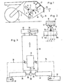
- FIG. 1 a vertical section through a mower is shown, which is attached by means of horizontal struts 1 the front of a carrier vehicle, not shown, is attached.
- the mower is driven, for example, by means of a PTO shaft of the carrier vehicle, which is also not shown, and which is connected to the transmission of the mower.
- the mower comprises a housing 2, which is guided on opposite sides by means of trailing wheels 3 on the floor.
- the actual mower can be seen, which is designed in the manner of a flail mower 4.
- This comprises a shaft 5 which runs transversely to the direction of travel and rotates in the direction of arrow f, on which cutting elements 6 are arranged distributed over the circumference.
- the exemplary embodiment shows three rows of cutting elements 6 that the Schlegelmähwerks 4 sequentially offset by 120 0 are articulated on the shaft 5 along the entire length of the shaft. 5 From Fig. 2 it is clear that each cutting element 6 consists of a Y-shaped member which is pivotally attached at one end about a bolt 8 between radially welded ears 9 on the shaft 5; This type of fastening means that each cutting element is axially fixed, so that it can only be pivoted about a bolt 8 within a radial plane.
- FIG. 2 the pin axes 10a, 10b, 10c of three cutting elements 6 arranged next to one another are shown. B. the left pin axis 10a the visible front, the right pin axis 10b on the hidden back of shaft 5 is assumed.
- the axial distance between two cutting elements 6 which follow one another in the axial direction is indicated by "d" in FIG. 2.
- a knife bar 11 fastened in the interior of the housing 2 has teeth 12, the pointed ends 13 of which engage between two leg pieces 14 forming an angle with one another at the ends of the Y-shaped cutting elements 6.
- the profile of the male connector 11 is interlocked with the profile of the envelope surface of the flail mower.
- This interlocking causes the upper or front closure of a storage space 7 below the knife bar 11.
- the mown, initially long-stemmed grass collects in this storage space 7, where it is held back by the knife bar 11 until it is caused by the multiple action of the cutting elements 6 is chopped into short stalks in the area of the storage space 7.
- the chopped piece goods then falls down on both sides of the shaft 5 from the housing.
- a chopping machine 16 is attached to the inside of the front housing wall 17 behind the knife bar 11.
- the housing 2 is closed on the side. In the representation acc. Fig. 1 is cut open one side wall, so that only the opposite side wall 18th is recognizable.
- the housing 2 is open towards the bottom, and also towards the front in the lower region.
- a chain curtain 19 is provided in the area of the front mowing opening. The direction of mowing of the mower is indicated by arrow p.
- FIG. 3 shows a top view of the diagram of a drive system.
- a mower unit 22, which is somewhat wider than the carrier vehicle 20, is suspended on the front of a carrier vehicle 20 with a mounted motor 21.
- This mower unit 22 is driven via a front PTO 24 of the carrier vehicle via a deflection gear 25.
- On the rear side two pairs of further mowing units are fastened to the carrier vehicle 20 and are staggered in the lateral direction to one another.
- a first pair with two mowing units 26, 27 attached directly to the rear of the vehicle is driven via a PTO shaft 28 of the body motor 21 via a drive shaft 29 of a common transmission 30. These two cutting units 26, 27 correspond approximately to the front cutting unit 22 in their respective cutting width.
- the outer pair of rear cutting units consists of two smaller cutting units 31, 32, which are each suspended from the housing of the leading rear cutting units 26, 27.
- the two outer rear mowing units 31, 22 are driven by the hydraulic circuits 33, 34 of the mounted motor 21.
- the cutting width it can be assumed, for example, that the three larger mowing units 22, 26, 27 each have a cutting width of 2.50 m, and the smaller rear mowing units 31, 32 each have a cutting width of 1.75 m.
- the total cutting width of the system is about 9 m.
Landscapes
- Life Sciences & Earth Sciences (AREA)
- Environmental Sciences (AREA)
- Engineering & Computer Science (AREA)
- Chemical & Material Sciences (AREA)
- Combustion & Propulsion (AREA)
- Transportation (AREA)
- Mechanical Engineering (AREA)
- Harvester Elements (AREA)
Applications Claiming Priority (2)
| Application Number | Priority Date | Filing Date | Title |
|---|---|---|---|
| DE3344987 | 1983-12-13 | ||
| DE3344987 | 1983-12-13 |
Publications (2)
| Publication Number | Publication Date |
|---|---|
| EP0149113A2 true EP0149113A2 (fr) | 1985-07-24 |
| EP0149113A3 EP0149113A3 (fr) | 1986-02-19 |
Family
ID=6216779
Family Applications (2)
| Application Number | Title | Priority Date | Filing Date |
|---|---|---|---|
| EP84114958A Withdrawn EP0149113A3 (fr) | 1983-12-13 | 1984-12-08 | Dispositif faucheur, en particulier pour pelouses d'aéroports |
| EP84115101A Withdrawn EP0149129A3 (fr) | 1983-12-13 | 1984-12-10 | Système d'entraínement sur un véhicule pour des appareils de travail divers à montage frontal ou arrière |
Family Applications After (1)
| Application Number | Title | Priority Date | Filing Date |
|---|---|---|---|
| EP84115101A Withdrawn EP0149129A3 (fr) | 1983-12-13 | 1984-12-10 | Système d'entraínement sur un véhicule pour des appareils de travail divers à montage frontal ou arrière |
Country Status (3)
| Country | Link |
|---|---|
| US (2) | US4631910A (fr) |
| EP (2) | EP0149113A3 (fr) |
| CA (1) | CA1230245A (fr) |
Families Citing this family (33)
| Publication number | Priority date | Publication date | Assignee | Title |
|---|---|---|---|---|
| FR2562758B1 (fr) * | 1984-04-12 | 1988-05-20 | Kuhn Sa | Faucheuse |
| DE3610141A1 (de) * | 1986-03-26 | 1987-10-01 | Claas Ohg | Maiserntegeraet |
| US4825970A (en) * | 1987-01-02 | 1989-05-02 | Mcvicar John A | Power takeoff shaft arrangement for a road vehicle |
| US4763744A (en) * | 1987-01-02 | 1988-08-16 | Mcvicar John A | Power takeoff shaft arrangement for a road vehicle |
| SE501903C2 (sv) * | 1987-09-08 | 1995-06-19 | Aake Hammarstrand | Slaghack |
| DE3910828C1 (fr) * | 1989-04-04 | 1990-06-13 | Ing. Alfred Schmidt Gmbh, 7822 St Blasien, De | |
| US5092422A (en) * | 1989-12-12 | 1992-03-03 | Clemson University | Multipurpose agricultural tractor |
| JPH0751389Y2 (ja) * | 1990-04-27 | 1995-11-22 | 株式会社神崎高級工機製作所 | トラクタの動力取出し装置 |
| US10361802B1 (en) | 1999-02-01 | 2019-07-23 | Blanding Hovenweep, Llc | Adaptive pattern recognition based control system and method |
| US8352400B2 (en) | 1991-12-23 | 2013-01-08 | Hoffberg Steven M | Adaptive pattern recognition based controller apparatus and method and human-factored interface therefore |
| US5482508A (en) * | 1995-03-31 | 1996-01-09 | Redekop; Leo L. | Apparatus for chopping and discharging straw from a combine harvester |
| US5802745A (en) * | 1995-09-15 | 1998-09-08 | Haseotes; Byron | Hydraulic system for a road vehicle |
| DE19535175A1 (de) * | 1995-09-25 | 1996-03-21 | Jakobi Wilhelm Dipl Ing Fh | Strohhäcksler zum Zerkleinern von Halmgut hinter den Kornabscheideeinrichtungen eines Mähdreschers |
| FR2741775B1 (fr) * | 1995-12-01 | 1998-01-23 | Bachmann Jacques | Rotor pour la coupe des vegetaux |
| US6038842A (en) * | 1996-02-26 | 2000-03-21 | Quiroga; Osvaldo R. | Rotary mower apparatus |
| US5761892A (en) * | 1996-02-26 | 1998-06-09 | Quiroga; Osvaldo R. | Rotary mower |
| DE29607651U1 (de) * | 1996-04-26 | 1997-08-28 | Kässbohrer Geländefahrzeug AG, 89250 Senden | Kettenfahrzeug |
| DE29702902U1 (de) * | 1997-02-19 | 1998-06-18 | Maschinenfabrik Kemper GmbH, 48703 Stadtlohn | Maschine zum reihenunabhängigen Mähen von Mais u.dgl. stengelartigem Erntegut |
| US7904187B2 (en) | 1999-02-01 | 2011-03-08 | Hoffberg Steven M | Internet appliance system and method |
| US6629406B2 (en) | 2001-08-08 | 2003-10-07 | Tardif 2000 | Apparatus for pruning field crops and low bushes |
| WO2003018202A1 (fr) * | 2001-08-31 | 2003-03-06 | Timberline Environmental Services | Tete coupante rotative et ensemble tete coupante |
| US20050193707A1 (en) * | 2002-03-06 | 2005-09-08 | Snapper Products, Inc. | Lawn mower with improved blade and blade housing |
| US6953398B1 (en) | 2002-04-12 | 2005-10-11 | Fisher Barton Blades, Inc. | Chopping blade |
| US7297053B2 (en) * | 2004-07-16 | 2007-11-20 | Cnh America Llc | Rotary crop residue chopper apparatus with stiffener having air flow generating capability and method of making the same |
| ES1061333Y (es) * | 2005-09-30 | 2006-06-01 | Alcay Jose Serrat | Maquina desbrozadora |
| ES2291092B1 (es) * | 2005-09-30 | 2009-01-16 | Jose Serrat Alcay | Maquina desbrozadora. |
| US7694500B2 (en) * | 2006-02-17 | 2010-04-13 | Deere & Company | Drive assembly and drive system for a combine head |
| US8099936B2 (en) * | 2009-01-27 | 2012-01-24 | Textron Innovations Inc. | Electrically powered flail mower |
| GB2494206A (en) * | 2011-09-05 | 2013-03-06 | Ransomes Jacobsen Ltd | Self-propelled grass cutting machine |
| US8978796B2 (en) | 2012-01-06 | 2015-03-17 | Silvio Gallazzini | Tractor having dual hydrostatic drive with single hand control and attachment adapter for powered attachments |
| US8806844B2 (en) * | 2012-02-24 | 2014-08-19 | Dom, L.L.C. | Flail motor head attachment |
| US9010467B2 (en) | 2012-04-23 | 2015-04-21 | Federal Signal Corporation | Shared power street sweeper |
| US10694666B2 (en) | 2018-04-16 | 2020-06-30 | Baum Machine, Inc. | Harvesting machine having a moisture removal mechanism and a crop converging mechanism |
Family Cites Families (21)
| Publication number | Priority date | Publication date | Assignee | Title |
|---|---|---|---|---|
| GB816421A (en) * | 1954-09-14 | 1959-07-15 | Wilder Ltd John | Improvements in or relating to choppers for green crop, straw and the like |
| US2734328A (en) * | 1956-02-14 | Lawn mower | ||
| US2408857A (en) * | 1942-11-19 | 1946-10-08 | Norman L James | Snowplow |
| US2689621A (en) * | 1947-09-13 | 1954-09-21 | Four Wheel Drive Auto Company | Truck with interrelated multiple prime movers, power take-off couplings, and operating controls therefor |
| CH304581A (de) * | 1951-04-18 | 1955-01-15 | Daimler Benz Ag | Kraftfahrzeug mit auf einer Pritsche angeordneten Sonderausrüstungsteilen. |
| FR1053394A (fr) * | 1951-07-04 | 1954-02-02 | Hache-paille | |
| US2758435A (en) * | 1954-06-01 | 1956-08-14 | Vernon J Lundell | Crop gathering and chopping device |
| FR1177669A (fr) * | 1956-06-27 | 1959-04-28 | Claas Maschf Gmbh Geb | Hache-paille |
| US2920434A (en) * | 1957-12-23 | 1960-01-12 | Richard L Ingram | Flexible gang mowing machine |
| FR1255151A (fr) * | 1960-03-19 | 1961-03-03 | Rover Co Ltd | Véhicule automobile |
| GB902170A (en) * | 1960-03-19 | 1962-07-25 | Karl Moertel | Drive for agricultural implements e.g. mowers on tractors, the front axle bearing of which is disposed coaxially of the engine shaft |
| FR1265689A (fr) * | 1960-08-19 | 1961-06-30 | Dispositif de moissonnage de fourrages verts et d'autres plantes | |
| US3224176A (en) * | 1964-06-18 | 1965-12-21 | Alexander P Taylor | Power operated gang mower |
| FR1427499A (fr) * | 1964-12-10 | 1966-02-04 | O M A Officine Macchine Agrico | Machine agricole pour ramasser, hacher et éparpiller la paille de riz et analogue |
| FR1584521A (fr) * | 1968-05-06 | 1969-12-26 | ||
| US3548951A (en) * | 1968-09-16 | 1970-12-22 | Tem Cole Inc | Multiple row crop harvesting machine |
| GB1272230A (en) * | 1968-11-29 | 1972-04-26 | Wilder Ltd John | Improvements in or relating to agricultural machines |
| US3678671A (en) * | 1971-02-26 | 1972-07-25 | Int Harvester Co | Flail shredder |
| GB1520108A (en) * | 1975-09-25 | 1978-08-02 | Wilder Ltd John | Flail crop chopperer |
| DE2628553A1 (de) * | 1976-06-25 | 1977-12-29 | Bermatingen Maschf | Messerwelle fuer schlegelmulchgeraete |
| US4277080A (en) * | 1978-03-16 | 1981-07-07 | Smitty's, Inc. | Quick hitch power frame |
-
1984
- 1984-12-08 EP EP84114958A patent/EP0149113A3/fr not_active Withdrawn
- 1984-12-10 EP EP84115101A patent/EP0149129A3/fr not_active Withdrawn
- 1984-12-13 US US06/681,219 patent/US4631910A/en not_active Expired - Fee Related
- 1984-12-13 CA CA000470034A patent/CA1230245A/fr not_active Expired
- 1984-12-13 US US06/681,093 patent/US4632200A/en not_active Expired - Fee Related
Also Published As
| Publication number | Publication date |
|---|---|
| EP0149129A2 (fr) | 1985-07-24 |
| US4632200A (en) | 1986-12-30 |
| US4631910A (en) | 1986-12-30 |
| CA1230245A (fr) | 1987-12-15 |
| EP0149113A3 (fr) | 1986-02-19 |
| EP0149129A3 (fr) | 1985-12-27 |
Similar Documents
| Publication | Publication Date | Title |
|---|---|---|
| EP1111985B1 (fr) | Dispositif permettant de moissonner des produits agricoles de type paille | |
| EP0856244B1 (fr) | Tondeuse de paillage | |
| DE2722554A1 (de) | Maehmaschine | |
| US4631910A (en) | Mower, especially for grass at airports | |
| DE29614549U1 (de) | Maschine zum reihenunabhängigen Mähen und Häckseln von Mais u.dgl. stengelartigem Erntegut | |
| DE102017207337A1 (de) | Mulchgerät zur Bearbeitung von auf einem Feld stehenden Pflanzenstümpfen | |
| DE1507154B1 (de) | Heuwerbungsmaschine mit einem Maehwerk und einer Aufbereitungseinrichtung | |
| DE2912466A1 (de) | Schnittgrasfoerdereinrichtung an sichelrasenmaehern | |
| DE3047643C2 (de) | An der Frontseite eines Fahrzeuges ankoppelbares, freischneidendes Scheibenmähwerk | |
| DE2947511C2 (de) | Absaugendes, ein Schlagmesserschneidwerk aufweisendes Mähwerk zum Anbringen an einem Tragfahrzeug | |
| EP0818136B1 (fr) | Dispositif pour hacher des végétaux | |
| EP2636296B1 (fr) | Barre porte-lames | |
| EP1967060A1 (fr) | Faneuse rotative | |
| DE3439226A1 (de) | Maehgeraet | |
| EP1541007B1 (fr) | Méthode et appareil pour couper et broyer en particulier des matières coupées hautes | |
| DE102020118051A1 (de) | Kreisel-Mähkopf sowie Verfahren für seinen Betrieb | |
| DE2905478A1 (de) | Maeh- und konditioniervorrichtung | |
| EP0069160B1 (fr) | Dispositif de fauchage et de conditionnement de récolte | |
| DE1582249A1 (de) | Kreiselmaeher mit Zusatzwerkzeugen | |
| DE69809151T2 (de) | Mehrzweckmäher | |
| DE19706592C1 (de) | Rasenmäher | |
| EP3841862B1 (fr) | Tête faucheuse rotative | |
| DE29607248U1 (de) | Aufbereiter für Halmgut | |
| DE2436308A1 (de) | Mehrzweckgeraet zum aufnehmen, zerkleinern und verteilen von auf schwaden liegendem stroh und dergleichen | |
| DE2446916C2 (de) | Feldhäcksler, insbesondere Maishäcksler |
Legal Events
| Date | Code | Title | Description |
|---|---|---|---|
| PUAI | Public reference made under article 153(3) epc to a published international application that has entered the european phase |
Free format text: ORIGINAL CODE: 0009012 |
|
| AK | Designated contracting states |
Designated state(s): AT BE CH DE FR GB IT LI LU NL SE |
|
| ITCL | It: translation for ep claims filed |
Representative=s name: BARZANO'E ZANARDO S.P.A. |
|
| TCNL | Nl: translation of patent claims filed | ||
| EL | Fr: translation of claims filed | ||
| PUAL | Search report despatched |
Free format text: ORIGINAL CODE: 0009013 |
|
| AK | Designated contracting states |
Designated state(s): AT BE CH DE FR GB IT LI LU NL SE |
|
| 17P | Request for examination filed |
Effective date: 19860516 |
|
| 17Q | First examination report despatched |
Effective date: 19870729 |
|
| STAA | Information on the status of an ep patent application or granted ep patent |
Free format text: STATUS: THE APPLICATION HAS BEEN WITHDRAWN |
|
| 18W | Application withdrawn |
Withdrawal date: 19871030 |
|
| RIN1 | Information on inventor provided before grant (corrected) |
Inventor name: HUEHN, EDGAR Inventor name: DOYEN, HANS-HENNING |