EP0149151A1 - Dispositif pour accélérer la réaction entre deux milieux réagissant dans un lit fluidifié - Google Patents
Dispositif pour accélérer la réaction entre deux milieux réagissant dans un lit fluidifié Download PDFInfo
- Publication number
- EP0149151A1 EP0149151A1 EP19840115368 EP84115368A EP0149151A1 EP 0149151 A1 EP0149151 A1 EP 0149151A1 EP 19840115368 EP19840115368 EP 19840115368 EP 84115368 A EP84115368 A EP 84115368A EP 0149151 A1 EP0149151 A1 EP 0149151A1
- Authority
- EP
- European Patent Office
- Prior art keywords
- phase
- chamber
- radially
- reaction
- drum
- Prior art date
- Legal status (The legal status is an assumption and is not a legal conclusion. Google has not performed a legal analysis and makes no representation as to the accuracy of the status listed.)
- Granted
Links
- 238000006243 chemical reaction Methods 0.000 title claims description 53
- 239000012071 phase Substances 0.000 claims description 57
- 239000000725 suspension Substances 0.000 claims description 17
- 239000007788 liquid Substances 0.000 claims description 12
- 239000007787 solid Substances 0.000 claims description 10
- 239000012429 reaction media Substances 0.000 claims description 9
- 239000002245 particle Substances 0.000 claims description 7
- 239000007790 solid phase Substances 0.000 claims description 7
- 238000012216 screening Methods 0.000 claims description 6
- 239000010419 fine particle Substances 0.000 claims description 4
- 239000007791 liquid phase Substances 0.000 claims description 4
- 239000012295 chemical reaction liquid Substances 0.000 claims description 3
- 239000007789 gas Substances 0.000 claims description 3
- 238000011001 backwashing Methods 0.000 claims description 2
- 230000008878 coupling Effects 0.000 claims 2
- 238000010168 coupling process Methods 0.000 claims 2
- 238000005859 coupling reaction Methods 0.000 claims 2
- 238000007599 discharging Methods 0.000 claims 1
- 238000002347 injection Methods 0.000 claims 1
- 239000007924 injection Substances 0.000 claims 1
- 239000012495 reaction gas Substances 0.000 claims 1
- 238000000034 method Methods 0.000 abstract description 3
- 239000012530 fluid Substances 0.000 description 7
- 238000007667 floating Methods 0.000 description 4
- 230000002706 hydrostatic effect Effects 0.000 description 4
- 230000015556 catabolic process Effects 0.000 description 2
- 238000006731 degradation reaction Methods 0.000 description 2
- 239000003344 environmental pollutant Substances 0.000 description 2
- 238000005188 flotation Methods 0.000 description 2
- 231100000719 pollutant Toxicity 0.000 description 2
- 239000002351 wastewater Substances 0.000 description 2
- 241000894006 Bacteria Species 0.000 description 1
- 102000004190 Enzymes Human genes 0.000 description 1
- 108090000790 Enzymes Proteins 0.000 description 1
- 230000001133 acceleration Effects 0.000 description 1
- QVGXLLKOCUKJST-UHFFFAOYSA-N atomic oxygen Chemical compound [O] QVGXLLKOCUKJST-UHFFFAOYSA-N 0.000 description 1
- 230000015572 biosynthetic process Effects 0.000 description 1
- 238000006555 catalytic reaction Methods 0.000 description 1
- 238000009792 diffusion process Methods 0.000 description 1
- 238000005516 engineering process Methods 0.000 description 1
- 238000000855 fermentation Methods 0.000 description 1
- 230000004151 fermentation Effects 0.000 description 1
- 239000000945 filler Substances 0.000 description 1
- 235000013490 limbo Nutrition 0.000 description 1
- 230000004060 metabolic process Effects 0.000 description 1
- 238000009629 microbiological culture Methods 0.000 description 1
- 239000001301 oxygen Substances 0.000 description 1
- 229910052760 oxygen Inorganic materials 0.000 description 1
- 230000005501 phase interface Effects 0.000 description 1
- 230000000717 retained effect Effects 0.000 description 1
- 238000007789 sealing Methods 0.000 description 1
- 239000000126 substance Substances 0.000 description 1
- 238000004065 wastewater treatment Methods 0.000 description 1
Images

Classifications
-
- C—CHEMISTRY; METALLURGY
- C02—TREATMENT OF WATER, WASTE WATER, SEWAGE, OR SLUDGE
- C02F—TREATMENT OF WATER, WASTE WATER, SEWAGE, OR SLUDGE
- C02F3/00—Biological treatment of water, waste water, or sewage
- C02F3/02—Aerobic processes
- C02F3/08—Aerobic processes using moving contact bodies
- C02F3/085—Fluidized beds
-
- B—PERFORMING OPERATIONS; TRANSPORTING
- B01—PHYSICAL OR CHEMICAL PROCESSES OR APPARATUS IN GENERAL
- B01J—CHEMICAL OR PHYSICAL PROCESSES, e.g. CATALYSIS OR COLLOID CHEMISTRY; THEIR RELEVANT APPARATUS
- B01J8/00—Chemical or physical processes in general, conducted in the presence of fluids and solid particles; Apparatus for such processes
- B01J8/18—Chemical or physical processes in general, conducted in the presence of fluids and solid particles; Apparatus for such processes with fluidised particles
- B01J8/20—Chemical or physical processes in general, conducted in the presence of fluids and solid particles; Apparatus for such processes with fluidised particles with liquid as a fluidising medium
-
- B—PERFORMING OPERATIONS; TRANSPORTING
- B01—PHYSICAL OR CHEMICAL PROCESSES OR APPARATUS IN GENERAL
- B01J—CHEMICAL OR PHYSICAL PROCESSES, e.g. CATALYSIS OR COLLOID CHEMISTRY; THEIR RELEVANT APPARATUS
- B01J8/00—Chemical or physical processes in general, conducted in the presence of fluids and solid particles; Apparatus for such processes
- B01J8/18—Chemical or physical processes in general, conducted in the presence of fluids and solid particles; Apparatus for such processes with fluidised particles
- B01J8/24—Chemical or physical processes in general, conducted in the presence of fluids and solid particles; Apparatus for such processes with fluidised particles according to "fluidised-bed" technique
- B01J8/38—Chemical or physical processes in general, conducted in the presence of fluids and solid particles; Apparatus for such processes with fluidised particles according to "fluidised-bed" technique with fluidised bed containing a rotatable device or being subject to rotation or to a circulatory movement, i.e. leaving a vessel and subsequently re-entering it
- B01J8/382—Chemical or physical processes in general, conducted in the presence of fluids and solid particles; Apparatus for such processes with fluidised particles according to "fluidised-bed" technique with fluidised bed containing a rotatable device or being subject to rotation or to a circulatory movement, i.e. leaving a vessel and subsequently re-entering it with a rotatable device only
-
- C—CHEMISTRY; METALLURGY
- C02—TREATMENT OF WATER, WASTE WATER, SEWAGE, OR SLUDGE
- C02F—TREATMENT OF WATER, WASTE WATER, SEWAGE, OR SLUDGE
- C02F1/00—Treatment of water, waste water, or sewage
- C02F1/38—Treatment of water, waste water, or sewage by centrifugal separation
-
- C—CHEMISTRY; METALLURGY
- C12—BIOCHEMISTRY; BEER; SPIRITS; WINE; VINEGAR; MICROBIOLOGY; ENZYMOLOGY; MUTATION OR GENETIC ENGINEERING
- C12M—APPARATUS FOR ENZYMOLOGY OR MICROBIOLOGY; APPARATUS FOR CULTURING MICROORGANISMS FOR PRODUCING BIOMASS, FOR GROWING CELLS OR FOR OBTAINING FERMENTATION OR METABOLIC PRODUCTS, i.e. BIOREACTORS OR FERMENTERS
- C12M25/00—Means for supporting, enclosing or fixing the microorganisms, e.g. immunocoatings
- C12M25/16—Particles; Beads; Granular material; Encapsulation
- C12M25/20—Fluidized bed
-
- C—CHEMISTRY; METALLURGY
- C12—BIOCHEMISTRY; BEER; SPIRITS; WINE; VINEGAR; MICROBIOLOGY; ENZYMOLOGY; MUTATION OR GENETIC ENGINEERING
- C12M—APPARATUS FOR ENZYMOLOGY OR MICROBIOLOGY; APPARATUS FOR CULTURING MICROORGANISMS FOR PRODUCING BIOMASS, FOR GROWING CELLS OR FOR OBTAINING FERMENTATION OR METABOLIC PRODUCTS, i.e. BIOREACTORS OR FERMENTERS
- C12M27/00—Means for mixing, agitating or circulating fluids in the vessel
- C12M27/10—Rotating vessel
-
- Y—GENERAL TAGGING OF NEW TECHNOLOGICAL DEVELOPMENTS; GENERAL TAGGING OF CROSS-SECTIONAL TECHNOLOGIES SPANNING OVER SEVERAL SECTIONS OF THE IPC; TECHNICAL SUBJECTS COVERED BY FORMER USPC CROSS-REFERENCE ART COLLECTIONS [XRACs] AND DIGESTS
- Y02—TECHNOLOGIES OR APPLICATIONS FOR MITIGATION OR ADAPTATION AGAINST CLIMATE CHANGE
- Y02W—CLIMATE CHANGE MITIGATION TECHNOLOGIES RELATED TO WASTEWATER TREATMENT OR WASTE MANAGEMENT
- Y02W10/00—Technologies for wastewater treatment
- Y02W10/10—Biological treatment of water, waste water, or sewage
Definitions
- the invention relates to a device for accelerating the reaction between two media according to the preamble of claim 1.
- the invention is therefore based on the object of accelerating the chemical, biochemical, metallurgical or catalytic reaction between two solid and liquid phase media by increasing the relative speed at the phase interfaces, where in particular, the mass transfer rates for media with a small particle size and / or with small density differences are to be increased.
- the Archimedes numbers according to the invention can be proportional to the centrifugal acceleration, i.e. e.g. be enlarged by at least a factor of 1000.
- the fluidized bed which can be subjected to a centrifugal field is formed by the screen cylinder of a screen drum which can be driven in rotation, wherein means are provided for generating a pressure gradient, on the basis of which the phase which keeps the other phase in suspension is essentially radial through the screen cylinder occurs and flows through the phase to be held in suspension.
- the sieve drum In order to accelerate the reaction between two media, of which the phase flowing through has a lower density and the phase to be held in suspension has a higher density, it is expedient to design the sieve drum according to claim 3, the pressure drop required for the flow passing through in a simple manner the radial adjustment of the first peeling tube and / or the setting of a larger filling height in the annular chamber can be controlled.
- the reaction space is preferably delimited by a second, radially inner sieve cylinder, by means of which the fluidized bed flow taking place in the reaction space can be kept free from flow disturbances caused by the first peeling tube.
- the radially inner screen cylinder can also be equipped with a filter medium which ensures that even the finest particles can be retained in the reaction chamber.
- the annular chamber and the line are designed as a closed system, as a result of which, in addition to the hydrostatic pressure of the radial liquid column, a pre-pressure can also be applied to the medium flowing through. The same can also be done for a short time for the purpose of backwashing the filter medium acting negative pressure are generated.
- reaction space there is the possibility of continuously or intermittently entering further solid and / or liquid reaction media into the reaction space, the additional reaction medium being able to be fed to the reaction space directly via the interior of the sieve drum or via the feed lines of the solid and / or liquid phases.
- a particularly advantageous embodiment includes both the features according to claims 3 to 9 and the features according to claims 10 to 17, whereby all solid and / or liquid media can be processed with only one device designed according to claim 18, regardless of their density.
- the devices according to claims 10 to 17 and 18 can also be equipped with a filter medium according to claim 19 for retaining the fine particles entrained in the phase flowing through.
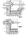
- a sieve drum 2 is attached to a rotatably mounted shaft 1, which consists essentially of the drum base 3, the drum wall 4 and an annular rim ring 5.
- a radially inner and a radially outer sieve cylinder 6 and 7, which surround a reaction space 8, are arranged within the sieve drum 2.
- An outflow annular chamber 12 is arranged axially outside of the annular flange ring 5, which in the embodiment according to FIG. 1 with the reaction space 8 via a radially outer drain hole 13 and in the embodiment according to FIG.
- the embodiment according to FIG. 4 has both the radially inner and the radially outer drain holes 13 and 14 arranged in the annular rim ring 5, which can be alternately closed with a sealing plug 15.
- a non-rotatable central filling tube 16 projects into the interior of the screening drum 2 according to FIGS. 1 to 4 and opens into a central opening 17 'of a guide disk 17 which is fastened to the drum base 3 at a parallel distance therefrom.
- the guide disk 17 forms on its outer edge with the drum base 3 an annular opening which leads into the reaction chamber 8.
- the central filling tube 16 can optionally be configured with a screw conveyor.
- the shaft 1 is provided with a bore 18, from which radially directed channels 19 leading into a closed annular chamber 11 are arranged.
- an inlet line 20 opens into the annular chamber 11 and a first peeling tube 21 projects into the interior of the sieve drum, the peeling opening of which is adjustable in the radial direction, possibly at intervals.
- a second peeling tube 22 projects into the discharge annular chamber 12 and can also be arranged so as to be adjustable in the radial direction.
- FIGS. 1 and 2 are suitable for accelerating the reaction between two media, of which a phase flowing through has a lower density and a phase to be held in suspension in a centrifugal field on a fluidized bed has a higher density.
- the fluidized bed is formed according to the embodiment of FIG. 1 in that the phase with a lower density is passed via line 20 into the annular chamber 11, in which a liquid column of radial height is established.
- the phase with a lower density passes through the flow bore 10 into the pressure chamber 9, from where the phase of lower density passes in a radially inward flow through the radially outer screen cylinder 7 and meets the phase with a higher density and flows through it, that it is kept in limbo.
- the phase of higher density reaches the reaction chamber 8 via the central filling tube 16 and the space formed by the drum base 3 and the guide disk 17 and is distributed in a floating flow movement over the radially outer sieve surface 7.
- the radially inner screen cylinder 6 serves as a shielding device.
- a filter medium (not shown) can be arranged on the inner sieve cylinder to retain fine particles entrained by the fluidized bed flow.
- the floating state of the solid phase of higher density is achieved in that a specific hydrostatic pressure drop between the annular chamber 11 and the reaction chamber 8 is set as a function of the density values of the two media and the speed of the sieve drum 2. This pressure drop can be determined by the inflow amount and the radial height setting of the first peeling tube 21.
- the pressure gradient that causes the floating state can also be achieved in that the annular chamber 11 is designed as a closed system, to which the phase of lower density can be supplied under pressure via a bore 18 and radially directed channels 19.
- the pressure is also increased by the fact that a higher hydrostatic pressure can also be set in the annular chamber 11 extending up to the shaft 1 due to the higher radial liquid column.
- the embodiment according to FIG. 3 is suitable for accelerating the reaction between two media, of which a phase flowing through has a higher density and a phase to be held in suspension in a centrifugal field has a lower density.
- the fluidized bed is formed according to the embodiment of FIG. 3 in that the phase is filled with a higher density via a filler tube 23 into the interior of the screen drum 2 and in a radially outward direction occurs through the radially inner screen cylinder 6 and on the solid phase with a lower density and flows through it in such a way that it is held in suspension above the radially inner screen cylinder 6.
- the phase of lower density passes through d ⁇
- the discharge of the phase of lower density which is conveyed from the fluidized bed via the radially inner drain hole 14 into the drain ring chamber 12, can be carried out via a radially and possibly intermittently adjustable second peeling tube 22 (FIG. 1) or, as shown in FIG. 3 , take place over a discharge edge 22 ', since the phase of lower density floats in the discharge annular chamber 12 and thus automatically promotes itself over the discharge edge.
- the radially outward flow of the phase of higher density can also be achieved or supported according to the embodiment according to FIG. 2 by the centrifuge space being designed as a closed system and subject to excess pressure.
- the liquid phase is transported into the room under normal pressure outside the centrifuge.
- a radially outer sieve cylinder 7 can be arranged, which can optionally also be covered with a filter medium.
- the inlet line 20 projecting into the annular chamber 11 can also be used as a peeling pipe with a peeling opening that can be adjusted in the radial direction. 3 and a first peeling tube 21 corresponding to the embodiment according to FIG. 1 protrude into the interior of the screening drum 2.
- the fluidized bed screening drum is like the embodiment according to FIG. 1 operable, so that the line 20 serves as an inlet line for the phase with a lower density and the first peeling tube 21 for its removal after flowing through the reaction chamber 8, the filling tube 23 remaining out of operation.
- the direction of flow of the two media of different densities flowing through is shown by the arrows with solid lines.
- the fluidized bed sieve drum is to be operated as the embodiment according to FIG. 3, the line 20 being used as a peeling pipe and the filling pipe 23 being used instead of the first peeling pipe 21.
- the direction of flow of the two media of different densities flowing through is shown with the arrows with broken lines.
- the embodiment according to FIG. 4 can also be equipped with a closed annular chamber according to FIG. 2, which can be supplied with the medium via the bore 18 and the channels 19 either under pressure or removed by means of negative pressure.
- Additional reaction partners in gaseous, liquid or solid form can be supplied to the reaction chamber 8 via the supply lines of all embodiments, such as the central filling tube 16, the bore 18 with the channels 19, the line 20 serving as the feed line and the filling tube 23.
- the central filling tube 16 and the guide disk 17 e.g. catalytically active solids are introduced into the reaction space.
- any type of additional reaction partners can also be introduced through separate lines into the central interior of the fluidized bed sieve drum or into the annular chamber 11.
- the phase to be held in suspension will consist of fine-grained solid particles which are held in suspension by the phase flowing through, the reaction liquid in a fluidized bed or a fluidized bed.
- a medium that has a higher density than the other medium can nevertheless become specifically lighter due to gas formation or gas binding, so that it tends to flotation.
- the embodiment according to FIG. 3 is preferably suitable for this, in which the phase tending to flotation is to be treated like a phase of lower density.
Landscapes
- Chemical & Material Sciences (AREA)
- Engineering & Computer Science (AREA)
- Organic Chemistry (AREA)
- Life Sciences & Earth Sciences (AREA)
- Health & Medical Sciences (AREA)
- Wood Science & Technology (AREA)
- Bioinformatics & Cheminformatics (AREA)
- Zoology (AREA)
- Microbiology (AREA)
- Biochemistry (AREA)
- Chemical Kinetics & Catalysis (AREA)
- Biotechnology (AREA)
- Biomedical Technology (AREA)
- General Engineering & Computer Science (AREA)
- General Health & Medical Sciences (AREA)
- Genetics & Genomics (AREA)
- Water Supply & Treatment (AREA)
- Combustion & Propulsion (AREA)
- Sustainable Development (AREA)
- Environmental & Geological Engineering (AREA)
- Hydrology & Water Resources (AREA)
- Biodiversity & Conservation Biology (AREA)
- Immunology (AREA)
- Analytical Chemistry (AREA)
- Mechanical Engineering (AREA)
- Devices And Processes Conducted In The Presence Of Fluids And Solid Particles (AREA)
- Apparatus Associated With Microorganisms And Enzymes (AREA)
Priority Applications (1)
| Application Number | Priority Date | Filing Date | Title |
|---|---|---|---|
| AT84115368T ATE45300T1 (de) | 1983-12-23 | 1984-12-13 | Vorrichtung zum beschleunigen der stoffumsetzung zwischen zwei in einem fliessbett reagierenden medien. |
Applications Claiming Priority (2)
| Application Number | Priority Date | Filing Date | Title |
|---|---|---|---|
| DE19833346861 DE3346861A1 (de) | 1983-12-23 | 1983-12-23 | Vorrichtung zum beschleunigen der stoffumsetzung zwischen zwei in einem fliessbett reagierenden medien |
| DE3346861 | 1983-12-23 |
Publications (2)
| Publication Number | Publication Date |
|---|---|
| EP0149151A1 true EP0149151A1 (fr) | 1985-07-24 |
| EP0149151B1 EP0149151B1 (fr) | 1989-08-09 |
Family
ID=6217983
Family Applications (1)
| Application Number | Title | Priority Date | Filing Date |
|---|---|---|---|
| EP19840115368 Expired EP0149151B1 (fr) | 1983-12-23 | 1984-12-13 | Dispositif pour accélérer la réaction entre deux milieux réagissant dans un lit fluidifié |
Country Status (6)
| Country | Link |
|---|---|
| US (2) | US4710356A (fr) |
| EP (1) | EP0149151B1 (fr) |
| JP (1) | JPS60156543A (fr) |
| AT (1) | ATE45300T1 (fr) |
| DE (1) | DE3346861A1 (fr) |
| IN (1) | IN162790B (fr) |
Cited By (3)
| Publication number | Priority date | Publication date | Assignee | Title |
|---|---|---|---|---|
| EP0285041A3 (en) * | 1987-04-02 | 1988-12-07 | Dornier System Gmbh | Process and apparatus for carrying out fluidised-bed reactors |
| EP0412467A1 (fr) * | 1989-08-11 | 1991-02-13 | Hans Ulrich Dr. Geyer | Procédé pour effectuer en continu des transformations enzymatiques à l'aide de biocatalyseurs immobilisés |
| WO1996014150A1 (fr) * | 1994-11-08 | 1996-05-17 | RWE-DEA Aktiengesellschaft für Mineralöl und Chemie | Procede de mise en contact de corps solides sous la forme de morceaux pouvant etre verses et procede |
Families Citing this family (2)
| Publication number | Priority date | Publication date | Assignee | Title |
|---|---|---|---|---|
| DE3719542A1 (de) * | 1987-06-11 | 1988-12-29 | Krauss Maffei Ag | Verfahren und vorrichtung zur durchfuehung von reaktionen zwischen einem gasfoermigen und einem fluessigen medium im zentrifugalfeld |
| DE3902271A1 (de) * | 1988-03-12 | 1989-09-21 | Buehler Ag Geb | Verfahren zum behandeln von schuettgut und vorrichtungen und anlage dazu |
Citations (5)
| Publication number | Priority date | Publication date | Assignee | Title |
|---|---|---|---|---|
| DE2629958A1 (de) * | 1975-07-04 | 1977-01-13 | Nishihara Env San Res Co Ltd | Filtriervorrichtung zum filtrieren von schlammigen fluessigkeiten |
| DE2529614A1 (de) * | 1975-07-03 | 1977-01-20 | Robert Dipl Ing Kohlheb | Rotationsfilterseparator vorzugsweise fuer die membranfiltration |
| DE2545680A1 (de) * | 1975-09-29 | 1977-04-21 | Nat Res Dev | Vorrichtung und verfahren zur durchfuehrung von reaktionen in einem wirbelbett |
| CH615841A5 (en) * | 1976-01-13 | 1980-02-29 | Mueller Hans Dr Ing Fa | Enzyme reactor |
| US4242450A (en) * | 1978-09-06 | 1980-12-30 | Snow Brand Milk Products Co., Ltd. | Method of hydrolyzing sugar, protein or the like and apparatus therefor |
Family Cites Families (12)
| Publication number | Priority date | Publication date | Assignee | Title |
|---|---|---|---|---|
| FR1065521A (fr) * | 1951-07-17 | 1954-05-26 | Procédé et dispositif pour le traitement de matières en menus morceaux, au moyen d'un fluide introduit par le bas | |
| GB1072908A (en) * | 1964-12-17 | 1967-06-21 | Head Wrightson & Co Ltd | Improvements in and relating to fluidizing beds |
| GB1395900A (en) * | 1971-10-14 | 1975-05-29 | Technical Dev Capital Ltd | Fluidized bed heat exchangers |
| US4039272A (en) * | 1975-09-26 | 1977-08-02 | Stone-Platt Fluidfire Limited | Apparatus and method for carrying out reactions in a fluidized bed |
| DE2622565C3 (de) * | 1976-05-20 | 1982-11-04 | Krauss-Maffei AG, 8000 München | Vorrichtung zum Trocknen von Feststoffpartikeln im Wirbelschichtverfahren |
| US4161103A (en) * | 1977-12-15 | 1979-07-17 | United Technologies Corporation | Centrifugal combustor with fluidized bed and construction thereof |
| JPS54114474A (en) * | 1978-02-28 | 1979-09-06 | Ebara Corp | Method and apparatus for centrifugal fluidization |
| JPS54141379A (en) * | 1978-04-25 | 1979-11-02 | Ebara Corp | Rotary type fluidizing method and its apparatus |
| GB1581672A (en) * | 1978-05-16 | 1980-12-17 | Coal Industry Patents Ltd | Fluidised bed combustion |
| US4282009A (en) * | 1979-11-01 | 1981-08-04 | Caterpillar Tractor Co. | Rotating fluidized bed gasifier system |
| US4343624A (en) * | 1979-12-10 | 1982-08-10 | Caterpillar Tractor Co. | Rotating fluidized bed hydrogen production system |
| JPH114474A (ja) * | 1997-06-13 | 1999-01-06 | Mitsubishi Electric Corp | 携帯端末装置及び情報提供システム |
-
1983
- 1983-12-23 DE DE19833346861 patent/DE3346861A1/de active Granted
-
1984
- 1984-12-13 EP EP19840115368 patent/EP0149151B1/fr not_active Expired
- 1984-12-13 AT AT84115368T patent/ATE45300T1/de not_active IP Right Cessation
- 1984-12-21 IN IN883/CAL/84A patent/IN162790B/en unknown
- 1984-12-21 US US06/685,233 patent/US4710356A/en not_active Expired - Fee Related
- 1984-12-24 JP JP59271104A patent/JPS60156543A/ja active Granted
-
1987
- 1987-09-09 US US07/095,582 patent/US4801336A/en not_active Expired - Fee Related
Patent Citations (5)
| Publication number | Priority date | Publication date | Assignee | Title |
|---|---|---|---|---|
| DE2529614A1 (de) * | 1975-07-03 | 1977-01-20 | Robert Dipl Ing Kohlheb | Rotationsfilterseparator vorzugsweise fuer die membranfiltration |
| DE2629958A1 (de) * | 1975-07-04 | 1977-01-13 | Nishihara Env San Res Co Ltd | Filtriervorrichtung zum filtrieren von schlammigen fluessigkeiten |
| DE2545680A1 (de) * | 1975-09-29 | 1977-04-21 | Nat Res Dev | Vorrichtung und verfahren zur durchfuehrung von reaktionen in einem wirbelbett |
| CH615841A5 (en) * | 1976-01-13 | 1980-02-29 | Mueller Hans Dr Ing Fa | Enzyme reactor |
| US4242450A (en) * | 1978-09-06 | 1980-12-30 | Snow Brand Milk Products Co., Ltd. | Method of hydrolyzing sugar, protein or the like and apparatus therefor |
Cited By (3)
| Publication number | Priority date | Publication date | Assignee | Title |
|---|---|---|---|---|
| EP0285041A3 (en) * | 1987-04-02 | 1988-12-07 | Dornier System Gmbh | Process and apparatus for carrying out fluidised-bed reactors |
| EP0412467A1 (fr) * | 1989-08-11 | 1991-02-13 | Hans Ulrich Dr. Geyer | Procédé pour effectuer en continu des transformations enzymatiques à l'aide de biocatalyseurs immobilisés |
| WO1996014150A1 (fr) * | 1994-11-08 | 1996-05-17 | RWE-DEA Aktiengesellschaft für Mineralöl und Chemie | Procede de mise en contact de corps solides sous la forme de morceaux pouvant etre verses et procede |
Also Published As
| Publication number | Publication date |
|---|---|
| DE3346861A1 (de) | 1985-06-27 |
| JPH0432694B2 (fr) | 1992-06-01 |
| EP0149151B1 (fr) | 1989-08-09 |
| JPS60156543A (ja) | 1985-08-16 |
| US4801336A (en) | 1989-01-31 |
| US4710356A (en) | 1987-12-01 |
| ATE45300T1 (de) | 1989-08-15 |
| IN162790B (fr) | 1988-07-09 |
| DE3346861C2 (fr) | 1993-09-16 |
Similar Documents
| Publication | Publication Date | Title |
|---|---|---|
| EP1444025B1 (fr) | Filtre comportant des elements filtrants rotatifs en forme de disque | |
| DE69320954T2 (de) | Wasserklärvorrichtung mit isolierung des ersten filtrats verbesserter rückspülung und blasenbildung | |
| EP0567601A1 (fr) | Procede et dispositif d'epuration d'eaux usees. | |
| DE2331192B2 (de) | Verfahren zu biologischen Denitrifikation von Abwasser | |
| DE2456953C3 (de) | Vorrichtung zum biologischen Aufbereiten von Abwässern | |
| EP0255642A2 (fr) | Réacteur de dispersion liquide-gaz | |
| DE2743956A1 (de) | Vorrichtung zur gleichzeitigen behandlung von primaeren und sekundaeren abwasserschlaemmen | |
| WO1993023139A1 (fr) | Dispositif de filtrage | |
| EP0237039A2 (fr) | Méthode pour la mise en oeuvre de procédés biotechnologiques produisant du gaz, dans des réacteurs à lit solide, et dispositifs propres à l'introduction et l'évacuation du gaz | |
| DE10004096A1 (de) | Wasseraufbereitungsanlage | |
| EP0149151B1 (fr) | Dispositif pour accélérer la réaction entre deux milieux réagissant dans un lit fluidifié | |
| WO1994001219A1 (fr) | Procede et dispositif de preparation gravimetrique de matieres solides | |
| EP1080265B1 (fr) | Procede et dispositif pour separer par flottation des substances polluantes contenues dans une suspension aqueuse de matieres fibreuses | |
| DE102005027509B4 (de) | Vorrichtung und Filterelement zum Filtern von Fluid-Feststoff-Gemischen | |
| DE1963919B2 (de) | Vorrichtung zum Herstellen von Suspensionen o.dgl., insbesondere von halogensilberhaltigen Suspensionen | |
| DE69700957T2 (de) | Verfahren zur durchführung einer behandlung in der anwesenheit einer zentrifugalen kraft sowie vorrichtung dafür | |
| EP1165200B1 (fr) | Procede et dispositif permettant de separer des materiaux | |
| EP0250998B1 (fr) | Appareil et procédé pour la culture de micro-organismes immobilisés | |
| EP0949948B1 (fr) | Procede et dispositif de filtration en continu de liquides | |
| DE102004009559A1 (de) | Membranbioreaktor und Verfahren zur Reinigung von Abwässern | |
| DE3326879A1 (de) | Biogasreaktor | |
| EP0621076B1 (fr) | Procédé pour la séparation de solides | |
| DE3900727A1 (de) | Verfahren und vorrichtung zur reinigung von abwasser oder abgasen | |
| DE69610913T2 (de) | Zentrifugalabscheider | |
| DE2739063A1 (de) | Verfahren und vorrichtung zum zentrifugieren |
Legal Events
| Date | Code | Title | Description |
|---|---|---|---|
| PUAI | Public reference made under article 153(3) epc to a published international application that has entered the european phase |
Free format text: ORIGINAL CODE: 0009012 |
|
| 17P | Request for examination filed |
Effective date: 19841213 |
|
| AK | Designated contracting states |
Designated state(s): AT BE CH FR GB IT LI NL SE |
|
| D17P | Request for examination filed (deleted) | ||
| R17P | Request for examination filed (corrected) |
Effective date: 19851205 |
|
| 17Q | First examination report despatched |
Effective date: 19870327 |
|
| GRAA | (expected) grant |
Free format text: ORIGINAL CODE: 0009210 |
|
| AK | Designated contracting states |
Kind code of ref document: B1 Designated state(s): AT BE CH FR GB IT LI NL SE |
|
| REF | Corresponds to: |
Ref document number: 45300 Country of ref document: AT Date of ref document: 19890815 Kind code of ref document: T |
|
| GBT | Gb: translation of ep patent filed (gb section 77(6)(a)/1977) | ||
| ITF | It: translation for a ep patent filed | ||
| ET | Fr: translation filed | ||
| NLXE | Nl: other communications concerning ep-patents (part 3 heading xe) |
Free format text: ON 891206 NEW PAGES 3 AND 4 OF THE TRANSLATION OF THE PATENT SPECIFICATION HAVE BEEN RECEIVED IN CONNECTION WITH CORRECTIONS ISSUED BY THE EUROPEAN PATENT OFFICE |
|
| ET1 | Fr: translation filed ** revision of the translation of the patent or the claims | ||
| PLBE | No opposition filed within time limit |
Free format text: ORIGINAL CODE: 0009261 |
|
| STAA | Information on the status of an ep patent application or granted ep patent |
Free format text: STATUS: NO OPPOSITION FILED WITHIN TIME LIMIT |
|
| 26N | No opposition filed | ||
| ITTA | It: last paid annual fee | ||
| PGFP | Annual fee paid to national office [announced via postgrant information from national office to epo] |
Ref country code: GB Payment date: 19921110 Year of fee payment: 9 |
|
| PGFP | Annual fee paid to national office [announced via postgrant information from national office to epo] |
Ref country code: SE Payment date: 19921111 Year of fee payment: 9 |
|
| PGFP | Annual fee paid to national office [announced via postgrant information from national office to epo] |
Ref country code: FR Payment date: 19921127 Year of fee payment: 9 |
|
| PGFP | Annual fee paid to national office [announced via postgrant information from national office to epo] |
Ref country code: BE Payment date: 19921209 Year of fee payment: 9 |
|
| PGFP | Annual fee paid to national office [announced via postgrant information from national office to epo] |
Ref country code: CH Payment date: 19921221 Year of fee payment: 9 |
|
| PGFP | Annual fee paid to national office [announced via postgrant information from national office to epo] |
Ref country code: AT Payment date: 19921230 Year of fee payment: 9 |
|
| PGFP | Annual fee paid to national office [announced via postgrant information from national office to epo] |
Ref country code: NL Payment date: 19921231 Year of fee payment: 9 |
|
| PG25 | Lapsed in a contracting state [announced via postgrant information from national office to epo] |
Ref country code: GB Effective date: 19931213 Ref country code: AT Effective date: 19931213 |
|
| PG25 | Lapsed in a contracting state [announced via postgrant information from national office to epo] |
Ref country code: SE Effective date: 19931214 |
|
| PG25 | Lapsed in a contracting state [announced via postgrant information from national office to epo] |
Ref country code: LI Effective date: 19931231 Ref country code: CH Effective date: 19931231 Ref country code: BE Effective date: 19931231 |
|
| BERE | Be: lapsed |
Owner name: KRAUSS-MAFFEI A.G. Effective date: 19931231 |
|
| PG25 | Lapsed in a contracting state [announced via postgrant information from national office to epo] |
Ref country code: NL Effective date: 19940701 |
|
| GBPC | Gb: european patent ceased through non-payment of renewal fee |
Effective date: 19931213 |
|
| NLV4 | Nl: lapsed or anulled due to non-payment of the annual fee | ||
| PG25 | Lapsed in a contracting state [announced via postgrant information from national office to epo] |
Ref country code: FR Effective date: 19940831 |
|
| REG | Reference to a national code |
Ref country code: CH Ref legal event code: PL |
|
| REG | Reference to a national code |
Ref country code: FR Ref legal event code: ST |
|
| EUG | Se: european patent has lapsed |
Ref document number: 84115368.7 Effective date: 19940710 |