EP0149221B1 - Trieur - Google Patents
Trieur Download PDFInfo
- Publication number
- EP0149221B1 EP0149221B1 EP84116165A EP84116165A EP0149221B1 EP 0149221 B1 EP0149221 B1 EP 0149221B1 EP 84116165 A EP84116165 A EP 84116165A EP 84116165 A EP84116165 A EP 84116165A EP 0149221 B1 EP0149221 B1 EP 0149221B1
- Authority
- EP
- European Patent Office
- Prior art keywords
- curved wall
- rotor
- particles
- annular zone
- classifier according
- Prior art date
- Legal status (The legal status is an assumption and is not a legal conclusion. Google has not performed a legal analysis and makes no representation as to the accuracy of the status listed.)
- Expired
Links
- 239000002245 particle Substances 0.000 claims abstract description 71
- 239000012530 fluid Substances 0.000 claims abstract description 16
- 238000011144 upstream manufacturing Methods 0.000 claims abstract description 9
- 238000005243 fluidization Methods 0.000 claims description 6
- 239000011236 particulate material Substances 0.000 claims description 5
- 230000005484 gravity Effects 0.000 claims description 4
- 239000007787 solid Substances 0.000 claims description 2
- 230000004323 axial length Effects 0.000 claims 1
- 239000004568 cement Substances 0.000 description 10
- 230000000694 effects Effects 0.000 description 8
- 230000006698 induction Effects 0.000 description 3
- 230000009471 action Effects 0.000 description 2
- 230000002411 adverse Effects 0.000 description 1
- 238000005054 agglomeration Methods 0.000 description 1
- 230000002776 aggregation Effects 0.000 description 1
- 238000013459 approach Methods 0.000 description 1
- 230000007423 decrease Effects 0.000 description 1
- 239000000463 material Substances 0.000 description 1
- 230000005012 migration Effects 0.000 description 1
- 238000013508 migration Methods 0.000 description 1
- 238000012986 modification Methods 0.000 description 1
- 230000004048 modification Effects 0.000 description 1
- 238000011084 recovery Methods 0.000 description 1
- 230000009467 reduction Effects 0.000 description 1
Images
Classifications
-
- B—PERFORMING OPERATIONS; TRANSPORTING
- B07—SEPARATING SOLIDS FROM SOLIDS; SORTING
- B07B—SEPARATING SOLIDS FROM SOLIDS BY SIEVING, SCREENING, SIFTING OR BY USING GAS CURRENTS; SEPARATING BY OTHER DRY METHODS APPLICABLE TO BULK MATERIAL, e.g. LOOSE ARTICLES FIT TO BE HANDLED LIKE BULK MATERIAL
- B07B7/00—Selective separation of solid materials carried by, or dispersed in, gas currents
- B07B7/08—Selective separation of solid materials carried by, or dispersed in, gas currents using centrifugal force
- B07B7/083—Selective separation of solid materials carried by, or dispersed in, gas currents using centrifugal force generated by rotating vanes, discs, drums, or brushes
-
- B—PERFORMING OPERATIONS; TRANSPORTING
- B07—SEPARATING SOLIDS FROM SOLIDS; SORTING
- B07B—SEPARATING SOLIDS FROM SOLIDS BY SIEVING, SCREENING, SIFTING OR BY USING GAS CURRENTS; SEPARATING BY OTHER DRY METHODS APPLICABLE TO BULK MATERIAL, e.g. LOOSE ARTICLES FIT TO BE HANDLED LIKE BULK MATERIAL
- B07B11/00—Arrangement of accessories in apparatus for separating solids from solids using gas currents
- B07B11/06—Feeding or discharging arrangements
Definitions
- the invention relates to classifiers particularly though not exclusively classifiers applicable to the classification of particulate cement.
- Classifiers which do not use a hopper are known (for example see GB-A-515717).
- a classifier for classifying particulate material into first and second particle size fractions constituted respectively by particles predominantly above a cut size of particle and particles predominantly below said cut size which classifier comprises a housing (10) having two opposed walls (32, 34) and a curved wall (30) which extends from one of said opposed walls (32,34) to the other, a rotor (14) mounted in said housing (10) between said opposed walls (32, 34), said curved wall (30) extending around said rotor (14) to define therewith an annular zone (50), an inlet opening (16) in said curved wall (30) through which fluid enters said annular zone (50), an inlet opening (16) into said annular zone for particulate material to be classified, an outlet opening (18) in said curved wall (30) through which said first fraction leaves said housing (10), a receptacle (12) having an inlet opening registered with said outlet opening (18) in said curved wall (30), an outlet opening (20) in one of said opposed walls (32, 34) through which fluid and said second fraction
- the curved wall has at least one second diverting means at a position upstream of the first diverting means.
- the curved wall has at least one inlet opening through which a secondary flow of fluid can enter the annular zone.
- each of the two walls has a baffle ring mounted thereon coaxial with the rotor and extending towards one another to restrain particles at the outer peripheries of the annular zone moving radially inwardly towards the rotor.
- the receptacle is of hollow cylindrical shape having its central longitudinal axis parallel to the axis of rotation of the rotor, the receptable being closed but having means which are openable to allow particles which have settled in the receptacle to be removed therefrom.
- the axis of rotation of the rotor is vertical.
- the classifier has a feeder which utilises particle fluidisation to feed particles to be classified into the stream or into the second stream.
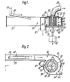
- the classifier shown in the drawings comprises the following principal parts: a housing 10; a receptacle 12; a rotor 14 in the housing 10; an inlet opening 16 providing an inlet to the housing 10; an outlet opening 18 providing an outlet from the housing 10 leading to the receptacle 12; an outlet opening 20 providing another outlet from the housing 10; a duct 22 leading to the inlet opening 16; a feeder 24 which utilises particle fluidisation leading into the duct 22; and a duct 26 leading away from the outlet opening 20.
- the housing 10 is made up of a curved wall 30 and upper and lower opposed walls 32, 34, respectively.
- the openings 16 and 18 are rectangular openings in the curved wall 30.
- the opening 18 is immediately upstream, relative to the direction of flow of the vortex flow stream, of the opening 16.
- the walls 32 and 34 as shown in Figure 1 are shaped to form opposed recesses at 36 and 38, respectively, and the opening 20 is a circular opening in the centre of the recessed part 36 of the wall 32.
- the rotor 14 is mounted on a vertical shaft 40 which is rotatable about an axis 42 concentrically positioned with respect to the recesses at 36 and 38.
- the rotor 14 is accommodated partly, at its ends, in the recesses at 36 and 28.
- the rotor 14 comprises an annular array of blades 44 each extending radially with respect to the axis 42, the blades 44 being supported at their ends by upper and lower end members 46 and 48, each consisting of a ring to which the ends of the blades 44 are attached and radially extending arms secured to the shaft 40.
- a variable speed motor 15 is mounted above the housing 10 and is connected to drive the shaft 40 and the rotor 14 in the sense indicated by the arrows in the drawings.
- the rotor 14 and the curved wall 30 together define an annular zone 50 in the housing 10.
- the shape of the curved wall 30 is what is known as a scroll. As shown in Figure 2 the wall 30 is not concentric with the axis 42 but instead the wall 30 approaches the axis 42 as the wall extends away from the radially outer edge of the inlet opening 16 around to the radially inner edge. The clearance between the wall 30 and the rotor 14 accordingly decreases in the same angular sense.
- the wall 30 makes a smooth continuation of the duct 22, which is of rectangular cross-section to match the opening 16. The air streams from the duct 22 enter the annular zone 50 tangentially to the curved wall 30.
- the feeder 24 is mounted in the top of the duct 22 and is inclined downwardly towards the inlet opening 16.
- the feeder 24 is operable to feed particulate cement into the air stream flowing in the part 52 of the duct 22. Particulate cement is fed downwardly to the feeder 24 through a conduit 54.
- the receptacle 12 is an upright hollow cylinder with its central longitudinal axis parallel to the axis 42.
- the upper end of the receptacle 12 is closed by a flat wall 70 and the lower end of the receptacle has a flange 72 by which it is secured to a closure device (not shown) such as a valve which is normally closed but which is operable to allow particles collected in the receptacle 12 to be removed.
- a closure device such as a valve which is normally closed but which is operable to allow particles collected in the receptacle 12 to be removed.
- the opening into the receptacle 12 is registered with the outlet opening 18 in the curved wall 30.
- the duct 26 is of circular cross-section and is connected to an induction fan (not shown).
- the curved wall 30 has a plate 56 positioned immediately upstream, relative to the direction of flow of the vortex flow stream, of the opening 18.
- the plate 56 acts to deflect particles on and immediately adjacent the wall 30 away from the wall 30.
- the plate 56 is at a slight angle to the wall 30 whereby, as can be seen from the drawing, particles are diverted away from the wall 30 generally tangentially to the middle of the annular zone 50.
- the plate extends only over a portion of the width of the wall 30 intermediate the edges of the wall 30.
- a second plate 58 is located on the curved wall 30 at a position 180° removed from the plate 56.
- baffle rings 60 and 62 Mounted concentrically with the rotor 14 on the walls 32, 34 are upper and lower baffle rings 60 and 62, respectively, which extend towards one another. Portions of the lower wall 34 between the curved wall 30 and the baffle ring 62, particularly in the regions close to the opening 18 can be perforated (as shown at 59) whereby air to maintain particle fluidisation can be drawn into the annular zone 50 through such portions.
- a second inlet 64 in the curved wall 30 is positioned intermediate the plates 56, 58 and is connected to a duct 66 through which secondary air flows tangentially into the annular zone 50.
- the median of the secondary air flow is tangential to the middle of the annular zone 50.
- the rotor 14 is rotated, the induction fan is operated to draw air through the classifier and the feeder 24 is operated to feed cement particles into the duct 22, a vortex flow of air and cement particles being established in the annular zone 50.
- the feeder 24 serves to prevent or reduce agglomeration of the particles. Some classification is already occurring in the duct 22 since the fluidisation of the particles by the feeder 24 tends to result in the heavier particles falling towards the base of the duct 22 under gravity.
- the cut size The particle size for which the forces are in balance is called the cut size.
- the effect of the rotor 14 is to influence the vortex flow and to enable the cut size to be adjusted by varying the rotor speed.
- the relatively finer particles move inwardly in the housing 10 with the air flow and pass between the rotor blades 44 towards the outlet opening 20, leave the classifier through the duct 26 and pass to a cement product collection point.
- the relatively coarser particles move outwards and ultimately reach the curved wall 30 and are restrained by the wall as they move with the rotating vortex flow. Upon reaching the outlet opening 18 the relatively coarser particles are freed from such restraint and can pass from the housing 10 through the opening 18 into the receptacle 12.
- Particles entering the receptacle 12 are constrained by the inner surface of the receptacle 12 to move in a circular path in the sense indicated by the arrow in Figure 2.
- the particles entering the receptacle 12 settle downwardly in the receptacle 12 under the effect of gravity and eventually come to rest at the bottom of the receptacle 12 supported by the closed valve mentioned above. From time to time the valve is operated to remove settled particles from the receptacle while the classifier is in operation without adverse effect on its performance.
- the vortex flow in the housing 10 induces a rotation of air in the receptacle 12 in the sense indicated by the arrow in Figure 2.
- the plate 56 causes the particles restrained by the curved wall 30 to be diverted away from the wall 30 generally tangentially to the middle of the annular zone 50. That action has the effect of reducing the amount of finer particles which leave the housing 10through the outlet opening 18.
- the effect of the plate 56 is believed to be two-fold. Firstly, as the particles restrained by the wall 30 are diverted away from the wall 30 it is only the coarser, and consequently, heavier particles that have the necessary energy to pass through the opening 18. Secondly, as the particles are diverted away from the curved wall 30, any finer particles which may have been trapped by the coarser particles are re-subjected to the classifying forces.
- the forces involved in classification also result in coarser particles moving to the outer peripheries of the annular zone 50 and then being forced inwardly towards the rotor 14.
- the baffle rings 60, 62 restrain such inward movement of the particles and the particles tend to spiral in the outer peripheries of the annular zone 50.
- the plates 56 and 58 extend only over an intermediate portion of the width of the curved wall 30 to ensure that the particles restrained by the baffle rings 60, 62 are removed from the annular zone 50 as soon as possible.
- the numbers of particles restrained by the lower baffle ring 62 can be sufficiently high to result in de- fluidisation of the particles as the air velocity slows down towards the opening 18 in the curved wall 30.
- the perforated portions 59 of the lower wall 34 ensures that the particles remain fluidised.
- a feature of this design is that the air requirements for conveying and classifying the cement particles are relatively low so leading to relatively lower power consumption overall.
- a further effect is to permit relatively high ratios of cement to air i.e. high cement loading of the air.
- the outlet duct 26 may be connected if preferred to a pressure recovery device (not shown) to reduce energy loss.
- a forced-draft fan could be connected to the duct 22 instead of or additionally to the induction fan connected to the duct 26.
- the wall 30 may be truly cylindrical instead of scroll shaped; the wall 34 may be curved or otherwise shaped to prevent or inhibit migration of relatively coarser particles over the wall towards and through the rotor 14.
- More than one outlet opening 18 may be provided which lead either into a common receptacle or into respective receptacles, for example
- the opening 20 may be positioned in the wall 34 beneath the rotor 14 instead of above the rotor, with corresponding re-positioning of the duct 26.
- the blades 44 may be shaped as desired and the indication given in the drawings is purely diagrammatic.
- the angle of the plate 56 to the wall 30 can be adjustable or the width of the plate 56 protruding into the annular zone 50 can be adjustable.
- the plate 58 can be adjustable in like manner.
- the plate 56 or 58 can be replaced by other diverting means, for example blocks, members with curvilinear surfaces or air inlets.
- the diverting means is an air inlet, it is effective over the full width of the wall 30 unless it is the diverting means immediately upstream of the opening 18.
- the diverting means are solid members more than one secondary air inlet may be provided in the wall 30.
- the particles can be fed directly into the annular zone 50 at one or more locations, for example, the duct 22 carrying air only.
- the duct 22 could be connected directly to a source of dust- laden air from a grinding mill, for example.
- the classifier can be oriented with the axis 42 horizontal instead of vertical. In that case the opening 18 would be at the lower side of the housing 10 and the receptacle would extend tangentially downwardly away from the wall 30; or extend downwardly though not tangentially.
- the drive shaft 40 may extend only through the lower wall 34 if preferred leaving the outlet duct 26 unobstructed.
- the classifier is relatively compact because a relatively large hopper beneath the rotor is unnecessary.
- the base of the classifier is relatively or completely plain and horizontal and the overall height of the classifier is relatively small so that the mounting of the classifier is quite simple. Furthermore, the arrangement of the classifier in relation to other duct work and to a cement grinding mill is simplified.
Landscapes
- Combined Means For Separation Of Solids (AREA)
- Cyclones (AREA)
- Magnetic Resonance Imaging Apparatus (AREA)
- Polarising Elements (AREA)
- Liquid Crystal Substances (AREA)
- Centrifugal Separators (AREA)
- Separation Of Solids By Using Liquids Or Pneumatic Power (AREA)
- Disintegrating Or Milling (AREA)
Claims (15)
Priority Applications (1)
| Application Number | Priority Date | Filing Date | Title |
|---|---|---|---|
| AT84116165T ATE45518T1 (de) | 1984-01-14 | 1984-12-22 | Sortierer. |
Applications Claiming Priority (2)
| Application Number | Priority Date | Filing Date | Title |
|---|---|---|---|
| GB848401009A GB8401009D0 (en) | 1984-01-14 | 1984-01-14 | Classifier |
| GB8401009 | 1984-01-14 |
Publications (3)
| Publication Number | Publication Date |
|---|---|
| EP0149221A2 EP0149221A2 (fr) | 1985-07-24 |
| EP0149221A3 EP0149221A3 (en) | 1987-01-07 |
| EP0149221B1 true EP0149221B1 (fr) | 1989-08-16 |
Family
ID=10555012
Family Applications (1)
| Application Number | Title | Priority Date | Filing Date |
|---|---|---|---|
| EP84116165A Expired EP0149221B1 (fr) | 1984-01-14 | 1984-12-22 | Trieur |
Country Status (8)
| Country | Link |
|---|---|
| US (1) | US4776950A (fr) |
| EP (1) | EP0149221B1 (fr) |
| JP (1) | JPS60156570A (fr) |
| AT (1) | ATE45518T1 (fr) |
| DE (1) | DE3479405D1 (fr) |
| DK (1) | DK162431C (fr) |
| ES (1) | ES539556A0 (fr) |
| GB (2) | GB8401009D0 (fr) |
Families Citing this family (9)
| Publication number | Priority date | Publication date | Assignee | Title |
|---|---|---|---|---|
| DE3814458A1 (de) * | 1988-04-28 | 1989-11-09 | Krupp Polysius Ag | Windsichter |
| US5472094A (en) * | 1993-10-04 | 1995-12-05 | Electric Power Research Institute | Flotation machine and process for removing impurities from coals |
| AT404234B (de) * | 1996-07-08 | 1998-09-25 | Pmt Gesteinsvermahlungstechnik | Sichtrad für einen windsichter |
| RU2123392C1 (ru) * | 1996-08-02 | 1998-12-20 | Белгородская государственная технологическая академия строительных материалов | Центробежный отбойно-вихревой сепаратор |
| ATE427169T1 (de) * | 2003-03-10 | 2009-04-15 | Aco Co Ltd | Verfahren und vorrichtung zur trennung |
| DE102005059282A1 (de) * | 2005-12-12 | 2007-06-14 | Polysius Ag | Sichter |
| GB2446580B (en) | 2007-02-16 | 2011-09-14 | Siemens Vai Metals Tech Ltd | Cyclone with classifier inlet and small particle by-pass |
| JP5014829B2 (ja) * | 2007-02-20 | 2012-08-29 | 株式会社テクノ高槻 | 集塵機構 |
| JP5148737B1 (ja) * | 2011-09-27 | 2013-02-20 | 株式会社赤松電機製作所 | 塵埃分離装置 |
Family Cites Families (24)
| Publication number | Priority date | Publication date | Assignee | Title |
|---|---|---|---|---|
| GB976876A (fr) * | 1900-01-01 | |||
| US2790508A (en) * | 1957-04-30 | Apparatus for removing dust by centrifugal force | ||
| US2026833A (en) * | 1936-01-07 | Separating device fob roughage | ||
| US1505742A (en) * | 1922-04-11 | 1924-08-19 | Albert H Stebbins | Concentrator |
| US1689104A (en) * | 1925-05-18 | 1928-10-23 | Ashley C Bennett | Gravity air cleaner for carburetors |
| US1922299A (en) * | 1930-06-26 | 1933-08-15 | Karl F Juengling | Dust collector |
| DE737374C (de) * | 1936-12-31 | 1943-07-12 | Hermannus Van Tongeren | Vom Staubgasstrom in einer ebenen Spirale durchstroemter Fliehkraftstaubabscheider |
| GB515717A (en) * | 1937-06-11 | 1939-12-12 | L Atomic Soc | Improvements in or relating to separators |
| US2361758A (en) * | 1937-06-11 | 1944-10-31 | Fligue Wladimir De | Separator |
| GB524343A (en) * | 1939-01-27 | 1940-08-05 | Nathan Mutch | Improvements in or relating to the grading or separation of particles of solids or liquids |
| US2290664A (en) * | 1940-06-13 | 1942-07-21 | Thomas B Allardice | Separating apparatus |
| US2367906A (en) * | 1942-01-09 | 1945-01-23 | Wall | Apparatus for separating wood flour |
| DE751473C (de) * | 1942-01-16 | 1953-07-06 | Kohlenscheidungs Ges M B H | Fliehkraftwindsichter |
| DE839153C (de) * | 1950-02-23 | 1952-05-15 | Alpine Ag Eisengiesserei | Verfahren zum Reinigen des Grobgutes von anhaftendem Feingut bei Windsichtern und Windsichter |
| US2846151A (en) * | 1953-08-17 | 1958-08-05 | Bayer Ag | Selective disintegration and separation of pigments |
| US2815860A (en) * | 1953-10-14 | 1957-12-10 | Arenco Ab | Method and apparatus for separating leaf tobacco |
| GB789274A (en) * | 1956-04-09 | 1958-01-15 | Microcyclomat Co | Centripetal classifier |
| US3168466A (en) * | 1962-03-15 | 1965-02-02 | Dredge Mfg Corp | Separator for metals in liquid suspension |
| US3326475A (en) * | 1964-06-01 | 1967-06-20 | Microcyclomat Co | Reject spouts |
| DE2012797C3 (de) * | 1970-03-18 | 1973-11-29 | G. Siempelkamp & Co, 4150 Krefeld | Vorrichtung zum Sichten von Schüttgütern |
| GB2051619A (en) * | 1979-07-02 | 1981-01-21 | Shell Int Research | Separation of gases from particle streams |
| EP0067894B1 (fr) * | 1981-06-19 | 1986-04-09 | OMYA GmbH | Séparateur centrifuge |
| US4390419A (en) * | 1981-10-16 | 1983-06-28 | Omya Gmbh | Centrifugal classifier |
| US4450071A (en) * | 1982-07-09 | 1984-05-22 | Foster Wheeler Energy Corporation | Adjustable particle classifier |
-
1984
- 1984-01-14 GB GB848401009A patent/GB8401009D0/en active Pending
- 1984-12-22 AT AT84116165T patent/ATE45518T1/de not_active IP Right Cessation
- 1984-12-22 EP EP84116165A patent/EP0149221B1/fr not_active Expired
- 1984-12-22 DE DE8484116165T patent/DE3479405D1/de not_active Expired
-
1985
- 1985-01-10 GB GB08500584A patent/GB2154908B/en not_active Expired
- 1985-01-11 DK DK015585A patent/DK162431C/da not_active IP Right Cessation
- 1985-01-14 JP JP60004824A patent/JPS60156570A/ja active Pending
- 1985-01-14 ES ES539556A patent/ES539556A0/es active Granted
-
1986
- 1986-12-17 US US06/942,945 patent/US4776950A/en not_active Expired - Fee Related
Also Published As
| Publication number | Publication date |
|---|---|
| DE3479405D1 (en) | 1989-09-21 |
| EP0149221A3 (en) | 1987-01-07 |
| GB8500584D0 (en) | 1985-02-13 |
| GB8401009D0 (en) | 1984-02-15 |
| ES8600976A1 (es) | 1985-11-01 |
| ES539556A0 (es) | 1985-11-01 |
| DK162431C (da) | 1992-03-23 |
| DK15585D0 (da) | 1985-01-11 |
| DK15585A (da) | 1985-07-15 |
| EP0149221A2 (fr) | 1985-07-24 |
| ATE45518T1 (de) | 1989-09-15 |
| DK162431B (da) | 1991-10-28 |
| GB2154908A (en) | 1985-09-18 |
| JPS60156570A (ja) | 1985-08-16 |
| US4776950A (en) | 1988-10-11 |
| GB2154908B (en) | 1987-12-23 |
Similar Documents
| Publication | Publication Date | Title |
|---|---|---|
| EP0152278B2 (fr) | Classeur de particules | |
| US5120431A (en) | Pneumatic centrifugal separator | |
| US4689141A (en) | Separator for sorting particulate material, with a plurality of separately adjustable guide vane sets | |
| US4597537A (en) | Vertical mill | |
| US4528091A (en) | Particle classifier | |
| CN1913981B (zh) | 颗粒状物质的气动分离器和由该气动分离器进行颗粒分离的方法 | |
| US4756729A (en) | Apparatus for separating dust from gases | |
| US6902126B2 (en) | Hybrid turbine classifier | |
| JPH0258989B2 (fr) | ||
| US4661244A (en) | Rotary basket air classifier | |
| KR890001390B1 (ko) | 입상물질 분리기 | |
| JPH05504296A (ja) | 連結される砕料分級機を有する鉛直型衝撃粉砕機 | |
| EP0159766B1 (fr) | Appareil pour le tri de particules | |
| US4776950A (en) | Classifier | |
| EP0224364A2 (fr) | Procédé et appareil de classement de grains inférieurs à 300 micromètres | |
| US2939579A (en) | Air classifier | |
| JP2823099B2 (ja) | 微粉砕設備 | |
| EP0519535A1 (fr) | Séparateur dynamique pour matières pulvérulentes, en particulier du ciment, et installation comportant ledit séparateur | |
| IE54422B1 (en) | Method and apparatus for sorting particulate material | |
| US4747939A (en) | Particle classifier | |
| JPH06206050A (ja) | 動的ローラミル空気分級機 | |
| CA1291067C (fr) | Dispositif de classification ou separation de solides | |
| JPH0551484U (ja) | 三方向分級機 | |
| JPH11267592A (ja) | 分級装置 | |
| JPS614581A (ja) | 分離器 |
Legal Events
| Date | Code | Title | Description |
|---|---|---|---|
| PUAI | Public reference made under article 153(3) epc to a published international application that has entered the european phase |
Free format text: ORIGINAL CODE: 0009012 |
|
| AK | Designated contracting states |
Designated state(s): AT DE FR GB |
|
| PUAL | Search report despatched |
Free format text: ORIGINAL CODE: 0009013 |
|
| AK | Designated contracting states |
Kind code of ref document: A3 Designated state(s): AT DE FR GB |
|
| 17P | Request for examination filed |
Effective date: 19870629 |
|
| 17Q | First examination report despatched |
Effective date: 19880316 |
|
| GRAA | (expected) grant |
Free format text: ORIGINAL CODE: 0009210 |
|
| AK | Designated contracting states |
Kind code of ref document: B1 Designated state(s): AT DE FR GB |
|
| REF | Corresponds to: |
Ref document number: 45518 Country of ref document: AT Date of ref document: 19890915 Kind code of ref document: T |
|
| REF | Corresponds to: |
Ref document number: 3479405 Country of ref document: DE Date of ref document: 19890921 |
|
| ET | Fr: translation filed | ||
| PLBE | No opposition filed within time limit |
Free format text: ORIGINAL CODE: 0009261 |
|
| STAA | Information on the status of an ep patent application or granted ep patent |
Free format text: STATUS: NO OPPOSITION FILED WITHIN TIME LIMIT |
|
| 26N | No opposition filed | ||
| PGFP | Annual fee paid to national office [announced via postgrant information from national office to epo] |
Ref country code: FR Payment date: 19911107 Year of fee payment: 8 |
|
| PGFP | Annual fee paid to national office [announced via postgrant information from national office to epo] |
Ref country code: AT Payment date: 19911112 Year of fee payment: 8 |
|
| PGFP | Annual fee paid to national office [announced via postgrant information from national office to epo] |
Ref country code: GB Payment date: 19911114 Year of fee payment: 8 |
|
| PGFP | Annual fee paid to national office [announced via postgrant information from national office to epo] |
Ref country code: DE Payment date: 19911121 Year of fee payment: 8 |
|
| PG25 | Lapsed in a contracting state [announced via postgrant information from national office to epo] |
Ref country code: GB Effective date: 19921222 Ref country code: AT Effective date: 19921222 |
|
| GBPC | Gb: european patent ceased through non-payment of renewal fee |
Effective date: 19921222 |
|
| PG25 | Lapsed in a contracting state [announced via postgrant information from national office to epo] |
Ref country code: FR Effective date: 19930831 |
|
| PG25 | Lapsed in a contracting state [announced via postgrant information from national office to epo] |
Ref country code: DE Effective date: 19930901 |
|
| REG | Reference to a national code |
Ref country code: FR Ref legal event code: ST |