EP0149228A2 - Moteur électrique, en particulier moteur à courant continu sans collecteur - Google Patents
Moteur électrique, en particulier moteur à courant continu sans collecteur Download PDFInfo
- Publication number
- EP0149228A2 EP0149228A2 EP84116201A EP84116201A EP0149228A2 EP 0149228 A2 EP0149228 A2 EP 0149228A2 EP 84116201 A EP84116201 A EP 84116201A EP 84116201 A EP84116201 A EP 84116201A EP 0149228 A2 EP0149228 A2 EP 0149228A2
- Authority
- EP
- European Patent Office
- Prior art keywords
- stator
- rotor
- electric motor
- support part
- bearing support
- Prior art date
- Legal status (The legal status is an assumption and is not a legal conclusion. Google has not performed a legal analysis and makes no representation as to the accuracy of the status listed.)
- Granted
Links
- 238000013016 damping Methods 0.000 claims abstract description 16
- XEEYBQQBJWHFJM-UHFFFAOYSA-N Iron Chemical compound [Fe] XEEYBQQBJWHFJM-UHFFFAOYSA-N 0.000 claims description 22
- 150000001875 compounds Chemical class 0.000 claims description 10
- 229910052742 iron Inorganic materials 0.000 claims description 10
- 238000005266 casting Methods 0.000 claims description 5
- 239000000853 adhesive Substances 0.000 claims description 3
- 230000001070 adhesive effect Effects 0.000 claims description 3
- 230000006698 induction Effects 0.000 claims description 3
- 238000007789 sealing Methods 0.000 claims description 3
- 238000003860 storage Methods 0.000 description 15
- 238000004804 winding Methods 0.000 description 5
- 230000005540 biological transmission Effects 0.000 description 2
- 239000004020 conductor Substances 0.000 description 2
- 230000005347 demagnetization Effects 0.000 description 2
- 230000018109 developmental process Effects 0.000 description 2
- 239000000203 mixture Substances 0.000 description 2
- 229920002635 polyurethane Polymers 0.000 description 2
- 239000004814 polyurethane Substances 0.000 description 2
- 238000004382 potting Methods 0.000 description 2
- 229910001047 Hard ferrite Inorganic materials 0.000 description 1
- 239000011358 absorbing material Substances 0.000 description 1
- XAGFODPZIPBFFR-UHFFFAOYSA-N aluminium Chemical compound [Al] XAGFODPZIPBFFR-UHFFFAOYSA-N 0.000 description 1
- 229910052782 aluminium Inorganic materials 0.000 description 1
- 230000004323 axial length Effects 0.000 description 1
- 239000011324 bead Substances 0.000 description 1
- 230000001419 dependent effect Effects 0.000 description 1
- 239000013013 elastic material Substances 0.000 description 1
- 229920001971 elastomer Polymers 0.000 description 1
- 229920006332 epoxy adhesive Polymers 0.000 description 1
- 230000004907 flux Effects 0.000 description 1
- 238000003475 lamination Methods 0.000 description 1
- 239000007788 liquid Substances 0.000 description 1
- 239000011553 magnetic fluid Substances 0.000 description 1
- 239000000696 magnetic material Substances 0.000 description 1
- 238000004519 manufacturing process Methods 0.000 description 1
- 239000000463 material Substances 0.000 description 1
- 230000015654 memory Effects 0.000 description 1
- AJCDFVKYMIUXCR-UHFFFAOYSA-N oxobarium;oxo(oxoferriooxy)iron Chemical compound [Ba]=O.O=[Fe]O[Fe]=O.O=[Fe]O[Fe]=O.O=[Fe]O[Fe]=O.O=[Fe]O[Fe]=O.O=[Fe]O[Fe]=O.O=[Fe]O[Fe]=O AJCDFVKYMIUXCR-UHFFFAOYSA-N 0.000 description 1
- 238000005192 partition Methods 0.000 description 1
- 239000004848 polyfunctional curative Substances 0.000 description 1
- 230000004044 response Effects 0.000 description 1
- 238000004904 shortening Methods 0.000 description 1
Images

Classifications
-
- H—ELECTRICITY
- H02—GENERATION; CONVERSION OR DISTRIBUTION OF ELECTRIC POWER
- H02K—DYNAMO-ELECTRIC MACHINES
- H02K1/00—Details of the magnetic circuit
- H02K1/06—Details of the magnetic circuit characterised by the shape, form or construction
- H02K1/12—Stationary parts of the magnetic circuit
- H02K1/18—Means for mounting or fastening magnetic stationary parts on to, or to, the stator structures
- H02K1/187—Means for mounting or fastening magnetic stationary parts on to, or to, the stator structures to inner stators
-
- H—ELECTRICITY
- H02—GENERATION; CONVERSION OR DISTRIBUTION OF ELECTRIC POWER
- H02K—DYNAMO-ELECTRIC MACHINES
- H02K11/00—Structural association of dynamo-electric machines with electric components or with devices for shielding, monitoring or protection
- H02K11/01—Structural association of dynamo-electric machines with electric components or with devices for shielding, monitoring or protection for shielding from electromagnetic fields, i.e. structural association with shields
- H02K11/014—Shields associated with stationary parts, e.g. stator cores
- H02K11/0141—Shields associated with casings, enclosures or brackets
-
- H—ELECTRICITY
- H02—GENERATION; CONVERSION OR DISTRIBUTION OF ELECTRIC POWER
- H02K—DYNAMO-ELECTRIC MACHINES
- H02K29/00—Motors or generators having non-mechanical commutating devices, e.g. discharge tubes or semiconductor devices
- H02K29/06—Motors or generators having non-mechanical commutating devices, e.g. discharge tubes or semiconductor devices with position sensing devices
- H02K29/08—Motors or generators having non-mechanical commutating devices, e.g. discharge tubes or semiconductor devices with position sensing devices using magnetic effect devices, e.g. Hall-plates, magneto-resistors
-
- H—ELECTRICITY
- H02—GENERATION; CONVERSION OR DISTRIBUTION OF ELECTRIC POWER
- H02K—DYNAMO-ELECTRIC MACHINES
- H02K5/00—Casings; Enclosures; Supports
- H02K5/04—Casings or enclosures characterised by the shape, form or construction thereof
- H02K5/16—Means for supporting bearings, e.g. insulating supports or means for fitting bearings in the bearing-shields
- H02K5/173—Means for supporting bearings, e.g. insulating supports or means for fitting bearings in the bearing-shields using bearings with rolling contact, e.g. ball bearings
- H02K5/1735—Means for supporting bearings, e.g. insulating supports or means for fitting bearings in the bearing-shields using bearings with rolling contact, e.g. ball bearings radially supporting the rotary shaft at only one end of the rotor
Definitions
- the invention relates to an electric motor, in particular in the form of a brushless DC motor, which is preferably intended for driving disk memories, but is also suitable for other drive tasks, especially in the office area, and which has an essentially cylindrical air gap between the stator and rotor, wherein the stator is attached to a bearing part for the bearing of the rotor shaft.
- the invention has for its object to provide a suitable for driving disk storage, but also of other devices, suitable electric motor, in particular a collectorless DC motor, which has a particularly low noise emission and which can be carried out at the same time with a very small, non-repeatable stroke.
- this object is achieved in that the stator is connected to the bearing support part via an elastic damping arrangement.
- bearing noises are effectively reduced, since sound waves generated in the bearing, for example the ball bearings, are no longer reflected on the stator and are therefore prevented from running back and forth between the bearing and the stator.
- noise generated electromagnetically in the stator is prevented from being reflected back and forth between the stator and the bearing.
- Such electromagnetically generated noises can occur in particular due to axial and / or radial electromagnetic interference between the rotor and the stator.
- the elastic damping arrangement is preferably arranged axially in the region of the bearing of the rotor shaft and is axially short. It can expediently have a soft casting compound between the stator and the bearing part, which advantageously, after curing, has an intermediate piece which is positively connected to the stator and / or the bearing support part forms. This intermediate piece can usefully have a ring shape.
- Such a damping arrangement can be produced in a particularly simple manner in terms of production and nevertheless ensures extensive damping between the bearing support part and the stator.
- the elastic damping arrangement can also have one or more prefabricated elastic components, in particular elastic O-rings.
- the O-ring preferably engages with a part of its cross section in a corresponding groove on the facing surfaces of the stator and / or bearing support part.
- the stator and the bearing support part are separated from one another in the region of at least a substantial part of their surfaces facing one another by an air gap which preferably extends over a large part of the axial stator iron length.
- an air gap which preferably extends over a large part of the axial stator iron length.
- the air gap preferably separates the stator and the bearing support part, especially in the area critical for noise transmission, which is adjacent to the bearing of the rotor shaft.
- stator and the bearing support part are preferably connected to one another essentially only in the region of the elastic damping arrangement, while they are otherwise separated from one another by the air gap.
- the rotor shaft is supported in two ball bearings, each with a different number of balls. This feature also lowers the noise emission, and it can be provided alone or together with one or more of the features of the invention discussed above.
- Electric motors of the type mentioned at the outset, in particular for driving disk stores, are known in which the bearing support part is in turn connected to a fastening flange which extends essentially perpendicular to the axis of the rotor shaft.
- the object set here can be achieved if the fastening flange has a sound-absorbing covering. This feature is also suitable for sole use as well as for use in combination with one or more of the measures described above.
- the fastening flange carries a printed circuit board and / or a magnetic shield
- the fastening flange is connected to the printed circuit board and / or the magnetic shield in a further embodiment of the invention to form a sound-absorbing multilayer body.
- a soft potting compound and / or an elastic adhesive can be expediently provided between the layers of the multilayer body. It was shown that such a substantial reduction in noise is possible even if, in the interest of the accuracy requirement for the position of the rotor axis with respect to the mounting flange, the latter and the bearing support part are integrally formed.
- openings distributed in the bottom of the rotor housing also lead to a noticeable reduction in noise emissions.
- This feature can also be provided alone or in combination with one or more of the previously explained features.
- the different size of the axial projections has the result that an axial force is exerted on the rotor, the magnet of which attempts to adjust itself magnetically symmetrically to the stator iron.
- This force is generally dependent on the rotational position, for example because the air gap between the rotor and the stator does not have the same dimensions everywhere. This can then lead to the electromagnetically generated noises already mentioned above.
- the stator carries an end plate, which interacts with the rotor magnet for axial symmetry of the magnetic field and preferably delimits at least part of the air gap in the region of the larger projection.
- electromagnetic noises can be reduced by making the induction in the central part of the rotor magnetic poles weaker at least in regions than in the edge regions of the rotor magnetic poles adjacent to the pole gaps in the region of the larger axial projection.
- Axial force symmetry can also be forced thereby, while at the same time a reliable response of the rotary position sensors is ensured.
- the motor has a cup-shaped rotor housing 11 which is concentric with a rotor shaft 12 and is firmly connected to the latter via a bushing 13 which is pressed into a central opening of the rotor housing.
- a plurality of permanent pieces or a one-piece permanent ring 14, which together with the components 11 to 13, form the rotor 15 of the motor 10, are mounted in the rotor housing 11, which consists of a magnetically highly conductive material.
- the permanent magnet ring 14 preferably consists of a mixture of hard ferrite, e.g. Barium ferrite, and elastic material. So it is a so-called rubber magnet. This is radially magnetized above the pole pitch trapezoidal or approximately trapezoidal with a relatively small pole gap.
- the rotor housing 11 can be manufactured as a deep-drawn part.
- the stator 16 of the motor 10 includes in particular a winding core 17, which consists of the actual stator iron 18, generally in the form of a stator lamination stack, and of end disks 19, 20 and which carries a stator winding 21.
- the winding core 17 is supported on a tubular bearing support part 22.
- the rotor shaft 12 is supported in the bearing support part 22 with the aid of two ball bearings 23, 24 which are supported with their mutually facing end faces on corresponding shoulders of the bearing support part 22 and which have different numbers of balls.
- egg A plate spring 25 bears against the underside of the inner ring of the ball bearing 23 and the end face of the bush 13 facing this ball bearing, as a result of which the ball bearings are axially braced against one another.
- the bearing support part forms, together with a mounting flange 26, a one-piece die-cast part.
- the bearing support part can also be press-fitted in a hub connected to the fastening flange or fixedly connected to the fastening flange in another way, for example soldered.
- the magnetic ring 14 and the winding core 17 delimit an essentially cylindrical air gap 27.
- the stator 16 is connected to the bearing support member 22 via an elastic damping arrangement which sits axially above the ball bearing 23 and consists of an annular intermediate piece 28 made of a soft sealing compound. In the region lying axially below the intermediate piece 28 in FIG. 1, the stator 16 and the bearing support part 22 are separated from one another by a narrow air gap 29.
- a bead of an elastic casting compound for example of a polyurethane hardener mixture, is expediently first introduced into a groove 30 on the lateral surface of the bearing support part 22.
- stator 16 is pushed onto the bearing support part 22 until an annular shoulder 31 of the end plate 20 rests with its inner surface against a section 32 of the lateral surface of the bearing support part 22 and with its end face against a shoulder 33 of the bearing support part 22.
- the stator 16 is centered with respect to the axis of the rotor shaft 12.
- the casting compound is then cured.
- the resulting elastic intermediate piece 28 provides a positive connection between the stator 16 and bearing support part 22, which effectively dampens the transmission of sound vibrations between the components 16, 22 in connection with the air gap 29.
- the mechanical connection of the components 16, 22 is located strength in the embodiment of F. 1 at a point from the location of the Main noise source is axially spaced.
- the wall of the bearing support part 22 can yield elastically in the region of the contact zone 34 of the outer ring of the ball bearing 23. All of this contributes to a significant reduction in noise emissions.
- the mounting flange 26 On the underside of the mounting flange 26 there are a shielding plate 35 made of a magnetically highly conductive material and a printed circuit board 36.
- the shielding plate 35 in conjunction with the rotor housing 11 and the ball bearing 24 prevents leakage of magnetic stray fields into the space 37 occupied by the hard storage plates.
- the drive electronics and possibly a speed control circuit, which are not illustrated in more detail, are located on the printed circuit board 36.
- the mounting flange 26, which is made, for example, of die-cast aluminum, has lugs 38 which protrude through recesses in the components 35, 36 and are placed on the spring clips 39 for holding the shielding plate 35.
- the fastening flange 26, the shielding plate 35 and the printed circuit board 36 are connected to one another in this way to form a sound-absorbing multilayer body. It goes without saying that the shielding plate and the printed circuit board may also swap places.
- both layers 40, 41 can be made of casting compound, adhesive or another material that dampens sound vibrations.
- the mounting flange 26 allows the motor 10 to be attached to a partition of a hard disk storage, which separates the space 37 from the rest of the device in a known manner (for example DE-A-31 08 204).
- a hub 42 which is used to receive one or more hard storage disks, is connected to the in Fig. 1 upper end of the rotor shaft 12 firmly connected.
- a magnetic fluid seal 43 is inserted into the bearing support part 22 in the area between the hub 42 and the bearing 24.
- the seal 43 consists of two pole pieces 44, 45, a permanent magnet ring 46 located between the pole pieces and a magnetic liquid which is introduced into an annular gap 47 between the magnetic ring 46 and the rotor shaft 12.
- a radial impeller 48 is attached, which attracts air in the central area and throws it radially outwards.
- a galvanomagnetic position sensor for example in the form of a Hall generator 49, is provided for controlling the commutation of the motor 10, which is soldered to the printed circuit board 36 and is influenced by the field of the magnetic ring 14.
- the rotor magnet 14 on the side facing the printed circuit board 36 projects further axially via the stator iron 18 than on the side facing the bottom of the rotor housing 11.
- a stator end plate 50 is provided on the larger axial projection side in order to counteract the axial interference forces which are thereby caused and which can likewise give rise to noise.
- the end plate 50 protrudes into the area of the axially protruding magnet 14 and delimits the air gap 27 there in a predetermined partial zone.
- the magnetic field is symmetrized.
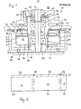
- the rotor magnet 14 can be partially demagnetized in a targeted manner in the region of the larger axial projection, as indicated in the development according to FIG. 2.
- the rotor magnetic poles are designated 51, the pole gaps 52 and the areas with weakened induction 53.
- the partial demagnetization regions 53 each end at a distance from the pole gaps. Therefore, a flawless approach speak of the sensor 49 guaranteed, while the partial demagnetization acts like a shortening of the larger projection with respect to the magnetic axial forces.
- FIG. 4 corresponds to that of FIG. 1 with the exception that an O-ring 54 is provided instead of the intermediate piece 28.
- the O-ring 54 engages in an annular groove 55 on the outer surface of the bearing support part 22. If necessary, a corresponding groove can also be provided in the stator iron.
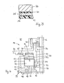
- FIG. 5 shows a particularly flat motor 60, parts which correspond functionally to the parts of the embodiment according to FIG. 1 being provided with the same reference symbols and not being explained again in detail.
- the sound-absorbing multilayer structure consisting of the mounting flange 26, shielding plate 35, printed circuit board 36 and the interposed layers 40, 41 and openings 61 distributed in the bottom of the rotor housing 11 serve to reduce noise.
- the rotor housing 11 equipped with the openings 61 reverses the principle of a piston loudspeaker in a closed box.
- seven equidistant openings are provided.
Landscapes
- Engineering & Computer Science (AREA)
- Power Engineering (AREA)
- Physics & Mathematics (AREA)
- Electromagnetism (AREA)
- Motor Or Generator Frames (AREA)
- Brushless Motors (AREA)
- Iron Core Of Rotating Electric Machines (AREA)
- Control Of Ac Motors In General (AREA)
- Control Of Direct Current Motors (AREA)
Priority Applications (2)
| Application Number | Priority Date | Filing Date | Title |
|---|---|---|---|
| AT84116201T ATE66322T1 (de) | 1983-12-28 | 1984-12-22 | Elektromotor, insbesondere kollektorloser gleichstrommotor. |
| EP91100691A EP0425478B2 (fr) | 1983-12-28 | 1984-12-22 | Moteur à rotor extérieur, en particulier moteur à courant continu sans collecteur |
Applications Claiming Priority (4)
| Application Number | Priority Date | Filing Date | Title |
|---|---|---|---|
| DE3347360 | 1983-12-28 | ||
| DE3347360A DE3347360C2 (de) | 1983-12-28 | 1983-12-28 | Kollektorloser Außenläufer-Gleichstrommotor |
| US57018784A | 1984-01-12 | 1984-01-12 | |
| US570187 | 1990-08-20 |
Related Child Applications (2)
| Application Number | Title | Priority Date | Filing Date |
|---|---|---|---|
| EP91100691.4 Division-Into | 1984-12-22 | ||
| EP91100690.6 Division-Into | 1984-12-22 |
Publications (3)
| Publication Number | Publication Date |
|---|---|
| EP0149228A2 true EP0149228A2 (fr) | 1985-07-24 |
| EP0149228A3 EP0149228A3 (en) | 1986-03-05 |
| EP0149228B1 EP0149228B1 (fr) | 1991-08-14 |
Family
ID=25816866
Family Applications (2)
| Application Number | Title | Priority Date | Filing Date |
|---|---|---|---|
| EP84116201A Expired - Lifetime EP0149228B1 (fr) | 1983-12-28 | 1984-12-22 | Moteur électrique, en particulier moteur à courant continu sans collecteur |
| EP91100691A Expired - Lifetime EP0425478B2 (fr) | 1983-12-28 | 1984-12-22 | Moteur à rotor extérieur, en particulier moteur à courant continu sans collecteur |
Family Applications After (1)
| Application Number | Title | Priority Date | Filing Date |
|---|---|---|---|
| EP91100691A Expired - Lifetime EP0425478B2 (fr) | 1983-12-28 | 1984-12-22 | Moteur à rotor extérieur, en particulier moteur à courant continu sans collecteur |
Country Status (3)
| Country | Link |
|---|---|
| EP (2) | EP0149228B1 (fr) |
| AT (1) | ATE123604T1 (fr) |
| DE (2) | DE3484927D1 (fr) |
Cited By (11)
| Publication number | Priority date | Publication date | Assignee | Title |
|---|---|---|---|---|
| WO1986001050A1 (fr) * | 1984-07-28 | 1986-02-13 | Papst-Motoren Gmbh & Co. Kg | Moteur a commande directe axialement compact |
| EP0218915A1 (fr) * | 1985-09-23 | 1987-04-22 | Siemens Aktiengesellschaft | Flasque de palier, en particulier pour le montage unilatéral à précharge axiale du rotor extérieur d'un moteur électrique |
| FR2600838A1 (fr) * | 1986-06-27 | 1987-12-31 | Etri Sa | Moteur electrique a palier perfectionne |
| US4724346A (en) * | 1985-09-23 | 1988-02-09 | Siemens Aktiengesellschaft | Permanent magnet-excited external rotor motor |
| WO1988007285A1 (fr) * | 1987-03-10 | 1988-09-22 | Torin Limited | Ameliorations apportees a des moteurs cc |
| WO1989005537A1 (fr) * | 1987-12-10 | 1989-06-15 | Papst-Motoren Gmbh & Co Kg | Moteur electrique |
| EP0339765A3 (fr) * | 1988-03-25 | 1991-02-06 | Magnetic Peripherals Inc. | Moteur d'axe pour unité de disque |
| DE4117801A1 (de) * | 1990-06-01 | 1991-12-05 | Mitsubishi Electric Corp | Elektromotor |
| US5410201A (en) * | 1990-06-01 | 1995-04-25 | Mitsubishi Denki Kabushiki Kaisha | Electric Motor |
| US5418414A (en) * | 1993-03-31 | 1995-05-23 | U.S. Philips Corporation | Electric motor with permanent-magnet excitation |
| WO1995034115A1 (fr) * | 1994-06-09 | 1995-12-14 | Digital Equipment International Ltd. | Moteur d'axe a faible bruit pour unite de disque de type winchester |
Families Citing this family (3)
| Publication number | Priority date | Publication date | Assignee | Title |
|---|---|---|---|---|
| DE4335966C2 (de) * | 1993-10-21 | 1998-07-16 | Fhp Motors Gmbh | Antriebsvorrichtung für eine Wasch- oder eine ähnliche Maschine mit einem kollektorlosen Gleichstrommotor |
| JPH1198757A (ja) * | 1997-09-26 | 1999-04-09 | Minebea Co Ltd | 磁気ディスク駆動用モータ |
| DE102016015365A1 (de) * | 2016-12-16 | 2018-06-21 | Ziehl-Abegg Se | Stator/Rotor für einen Elektromotor und Elektromotor mit einem Rotor und/oder einem Stator |
Family Cites Families (6)
| Publication number | Priority date | Publication date | Assignee | Title |
|---|---|---|---|---|
| DE1924729C3 (de) * | 1969-05-14 | 1978-08-31 | Papst-Motoren Kg, 7742 St Georgen | Isolationsanordnung eines Elektrokleinmotors |
| DE7614054U1 (de) * | 1976-05-04 | 1976-08-26 | Skf Kugellagerfabriken Gmbh, 8720 Schweinfurt | Aussenlaeufermotor |
| DE2811283A1 (de) * | 1978-03-15 | 1979-09-20 | Siemens Ag | Halterung des staenderblechpaketes im staendergehaeuse |
| DE3135385A1 (de) * | 1980-03-05 | 1983-03-17 | Papst-Motoren GmbH & Co KG, 7742 St Georgen | Plattenspeicher |
| DE3153746C2 (de) * | 1980-12-05 | 1995-04-13 | Papst Motoren Gmbh & Co Kg | Antriebsvorrichtung für magnetische Festplattenspeicher |
| DE3404466A1 (de) * | 1984-02-08 | 1985-08-08 | Ebm Elektrobau Mulfingen Gmbh & Co, 7119 Mulfingen | Aussenlaeufermotor |
-
1984
- 1984-12-22 AT AT91100691T patent/ATE123604T1/de not_active IP Right Cessation
- 1984-12-22 DE DE8484116201T patent/DE3484927D1/de not_active Expired - Lifetime
- 1984-12-22 EP EP84116201A patent/EP0149228B1/fr not_active Expired - Lifetime
- 1984-12-22 DE DE3486391T patent/DE3486391D1/de not_active Expired - Fee Related
- 1984-12-22 EP EP91100691A patent/EP0425478B2/fr not_active Expired - Lifetime
Cited By (14)
| Publication number | Priority date | Publication date | Assignee | Title |
|---|---|---|---|---|
| WO1986001050A1 (fr) * | 1984-07-28 | 1986-02-13 | Papst-Motoren Gmbh & Co. Kg | Moteur a commande directe axialement compact |
| US4724346A (en) * | 1985-09-23 | 1988-02-09 | Siemens Aktiengesellschaft | Permanent magnet-excited external rotor motor |
| EP0218915A1 (fr) * | 1985-09-23 | 1987-04-22 | Siemens Aktiengesellschaft | Flasque de palier, en particulier pour le montage unilatéral à précharge axiale du rotor extérieur d'un moteur électrique |
| US4867581A (en) * | 1985-09-23 | 1989-09-19 | Siemens Aktiengesellschaft | Bearing housing, especially for a unilaterally and axially braced external-rotor motor |
| US4783608A (en) * | 1986-06-27 | 1988-11-08 | Etudes Techniques Et Representations Industrielles E.T.R.I. | Electric motor with an improved bearing |
| EP0251896A1 (fr) * | 1986-06-27 | 1988-01-07 | ETUDES TECHNIQUES ET REPRESENTATIONS INDUSTRIELLES E.T.R.I Société Anonyme | Moteur électrique à palier perfectionné |
| FR2600838A1 (fr) * | 1986-06-27 | 1987-12-31 | Etri Sa | Moteur electrique a palier perfectionne |
| WO1988007285A1 (fr) * | 1987-03-10 | 1988-09-22 | Torin Limited | Ameliorations apportees a des moteurs cc |
| WO1989005537A1 (fr) * | 1987-12-10 | 1989-06-15 | Papst-Motoren Gmbh & Co Kg | Moteur electrique |
| EP0339765A3 (fr) * | 1988-03-25 | 1991-02-06 | Magnetic Peripherals Inc. | Moteur d'axe pour unité de disque |
| DE4117801A1 (de) * | 1990-06-01 | 1991-12-05 | Mitsubishi Electric Corp | Elektromotor |
| US5410201A (en) * | 1990-06-01 | 1995-04-25 | Mitsubishi Denki Kabushiki Kaisha | Electric Motor |
| US5418414A (en) * | 1993-03-31 | 1995-05-23 | U.S. Philips Corporation | Electric motor with permanent-magnet excitation |
| WO1995034115A1 (fr) * | 1994-06-09 | 1995-12-14 | Digital Equipment International Ltd. | Moteur d'axe a faible bruit pour unite de disque de type winchester |
Also Published As
| Publication number | Publication date |
|---|---|
| EP0425478A2 (fr) | 1991-05-02 |
| EP0425478A3 (en) | 1992-10-07 |
| EP0149228B1 (fr) | 1991-08-14 |
| EP0425478B2 (fr) | 1999-12-01 |
| DE3484927D1 (de) | 1991-09-19 |
| EP0149228A3 (en) | 1986-03-05 |
| ATE123604T1 (de) | 1995-06-15 |
| DE3486391D1 (de) | 1995-07-13 |
| EP0425478B1 (fr) | 1995-06-07 |
Similar Documents
| Publication | Publication Date | Title |
|---|---|---|
| DE3347360C2 (de) | Kollektorloser Außenläufer-Gleichstrommotor | |
| DE3519824C2 (de) | Plattenspeichergerät | |
| EP0425478B1 (fr) | Moteur à rotor extérieur, en particulier moteur à courant continu sans collecteur | |
| DE3300574C2 (fr) | ||
| DE3144629C2 (fr) | ||
| DE2919581A1 (de) | Zweipulsiger kollektorloser gleichstrommotor | |
| DE3808222A1 (de) | Aufbau eines buerstenlosen flachtyp-gleichstrommotors | |
| DE3327123A1 (de) | Antriebsanordnung fuer signalverarbeitende geraete | |
| DE3049334A1 (de) | "antriebsvorrichtung fuer magnetische festplattenspeicher" | |
| DE4121428A1 (de) | Spindelmotor, insbesondere fuer plattenspeicher | |
| DE3135385A1 (de) | Plattenspeicher | |
| DE3149943C2 (de) | Zweiphasenschrittmotor | |
| DE2237250A1 (de) | Drehstellungs-wandler | |
| DE69121595T2 (de) | Drehendes elektromagnetisches einphasenbetätigungsorgan | |
| DE102005023841A1 (de) | Ausgleichsaufbau für einen Motor | |
| DE8702998U1 (de) | Elektrokleinstmotor | |
| DE4021599A1 (de) | Buerstenloser gleichstrommotor | |
| WO1999005769A1 (fr) | Moteur a pôles a griffes | |
| DE3331754A1 (de) | Kollektorloser gleichstrommotor | |
| DE2927958C2 (fr) | ||
| EP1661229B1 (fr) | Moteur electrique pourvu d'une bague de reflux | |
| DE3546933B4 (de) | Festplattenspeicher | |
| DE8221291U1 (de) | Kollektorloser gleichstrommotor fuer signalverarbeitende geraete | |
| DE3153740C2 (de) | Antriebsvorrichtung für Festplattenspeicher | |
| DE4232850B4 (de) | Flachbauender, bürstenloser Gleichstrommotor zum Antrieb eines Kleingebläses |
Legal Events
| Date | Code | Title | Description |
|---|---|---|---|
| PUAI | Public reference made under article 153(3) epc to a published international application that has entered the european phase |
Free format text: ORIGINAL CODE: 0009012 |
|
| AK | Designated contracting states |
Designated state(s): AT BE CH DE FR GB IT LI LU NL SE |
|
| RBV | Designated contracting states (corrected) |
Designated state(s): AT CH DE FR GB IT LI |
|
| PUAL | Search report despatched |
Free format text: ORIGINAL CODE: 0009013 |
|
| AK | Designated contracting states |
Kind code of ref document: A3 Designated state(s): AT CH DE FR GB IT LI |
|
| 17P | Request for examination filed |
Effective date: 19860905 |
|
| 17Q | First examination report despatched |
Effective date: 19881124 |
|
| ITF | It: translation for a ep patent filed | ||
| GRAA | (expected) grant |
Free format text: ORIGINAL CODE: 0009210 |
|
| AK | Designated contracting states |
Kind code of ref document: B1 Designated state(s): AT CH DE FR GB IT LI |
|
| REF | Corresponds to: |
Ref document number: 66322 Country of ref document: AT Date of ref document: 19910815 Kind code of ref document: T |
|
| XX | Miscellaneous (additional remarks) |
Free format text: TEILANMELDUNG 91100690.6 EINGEREICHT AM 22/12/84. |
|
| GBT | Gb: translation of ep patent filed (gb section 77(6)(a)/1977) | ||
| REF | Corresponds to: |
Ref document number: 3484927 Country of ref document: DE Date of ref document: 19910919 |
|
| PG25 | Lapsed in a contracting state [announced via postgrant information from national office to epo] |
Ref country code: LI Effective date: 19911231 Ref country code: CH Effective date: 19911231 Ref country code: AT Effective date: 19911231 |
|
| EN | Fr: translation not filed | ||
| PG25 | Lapsed in a contracting state [announced via postgrant information from national office to epo] |
Ref country code: FR Effective date: 19920103 |
|
| PLBE | No opposition filed within time limit |
Free format text: ORIGINAL CODE: 0009261 |
|
| STAA | Information on the status of an ep patent application or granted ep patent |
Free format text: STATUS: NO OPPOSITION FILED WITHIN TIME LIMIT |
|
| 26N | No opposition filed | ||
| REG | Reference to a national code |
Ref country code: CH Ref legal event code: PL |
|
| REG | Reference to a national code |
Ref country code: FR Ref legal event code: ST |
|
| REG | Reference to a national code |
Ref country code: GB Ref legal event code: 732E |
|
| ITPR | It: changes in ownership of a european patent |
Owner name: CESSIONE;PAPST LICENSING GMBH |
|
| REG | Reference to a national code |
Ref country code: GB Ref legal event code: IF02 |
|
| PGFP | Annual fee paid to national office [announced via postgrant information from national office to epo] |
Ref country code: GB Payment date: 20021220 Year of fee payment: 19 |
|
| PGFP | Annual fee paid to national office [announced via postgrant information from national office to epo] |
Ref country code: DE Payment date: 20030224 Year of fee payment: 19 |
|
| PG25 | Lapsed in a contracting state [announced via postgrant information from national office to epo] |
Ref country code: GB Free format text: LAPSE BECAUSE OF NON-PAYMENT OF DUE FEES Effective date: 20031222 |
|
| PG25 | Lapsed in a contracting state [announced via postgrant information from national office to epo] |
Ref country code: DE Free format text: LAPSE BECAUSE OF NON-PAYMENT OF DUE FEES Effective date: 20040701 |
|
| GBPC | Gb: european patent ceased through non-payment of renewal fee |
Effective date: 20031222 |