EP0149292A2 - Längenregulierbare Form zum Herstellen von Behältern - Google Patents
Längenregulierbare Form zum Herstellen von Behältern Download PDFInfo
- Publication number
- EP0149292A2 EP0149292A2 EP84300255A EP84300255A EP0149292A2 EP 0149292 A2 EP0149292 A2 EP 0149292A2 EP 84300255 A EP84300255 A EP 84300255A EP 84300255 A EP84300255 A EP 84300255A EP 0149292 A2 EP0149292 A2 EP 0149292A2
- Authority
- EP
- European Patent Office
- Prior art keywords
- mold
- end plate
- core
- mold cavity
- cavity
- Prior art date
- Legal status (The legal status is an assumption and is not a legal conclusion. Google has not performed a legal analysis and makes no representation as to the accuracy of the status listed.)
- Withdrawn
Links
Images
Classifications
-
- B—PERFORMING OPERATIONS; TRANSPORTING
- B29—WORKING OF PLASTICS; WORKING OF SUBSTANCES IN A PLASTIC STATE IN GENERAL
- B29C—SHAPING OR JOINING OF PLASTICS; SHAPING OF MATERIAL IN A PLASTIC STATE, NOT OTHERWISE PROVIDED FOR; AFTER-TREATMENT OF THE SHAPED PRODUCTS, e.g. REPAIRING
- B29C44/00—Shaping by internal pressure generated in the material, e.g. swelling or foaming ; Producing porous or cellular expanded plastics articles
- B29C44/34—Auxiliary operations
- B29C44/58—Moulds
- B29C44/585—Moulds with adjustable size of the mould cavity
-
- B—PERFORMING OPERATIONS; TRANSPORTING
- B29—WORKING OF PLASTICS; WORKING OF SUBSTANCES IN A PLASTIC STATE IN GENERAL
- B29C—SHAPING OR JOINING OF PLASTICS; SHAPING OF MATERIAL IN A PLASTIC STATE, NOT OTHERWISE PROVIDED FOR; AFTER-TREATMENT OF THE SHAPED PRODUCTS, e.g. REPAIRING
- B29C33/00—Moulds or cores; Details thereof or accessories therefor
- B29C33/30—Mounting, exchanging or centering
- B29C33/308—Adjustable moulds
-
- B—PERFORMING OPERATIONS; TRANSPORTING
- B29—WORKING OF PLASTICS; WORKING OF SUBSTANCES IN A PLASTIC STATE IN GENERAL
- B29C—SHAPING OR JOINING OF PLASTICS; SHAPING OF MATERIAL IN A PLASTIC STATE, NOT OTHERWISE PROVIDED FOR; AFTER-TREATMENT OF THE SHAPED PRODUCTS, e.g. REPAIRING
- B29C44/00—Shaping by internal pressure generated in the material, e.g. swelling or foaming ; Producing porous or cellular expanded plastics articles
- B29C44/34—Auxiliary operations
- B29C44/36—Feeding the material to be shaped
- B29C44/38—Feeding the material to be shaped into a closed space, i.e. to make articles of definite length
- B29C44/44—Feeding the material to be shaped into a closed space, i.e. to make articles of definite length in solid form
- B29C44/445—Feeding the material to be shaped into a closed space, i.e. to make articles of definite length in solid form in the form of expandable granules, particles or beads
-
- B—PERFORMING OPERATIONS; TRANSPORTING
- B29—WORKING OF PLASTICS; WORKING OF SUBSTANCES IN A PLASTIC STATE IN GENERAL
- B29C—SHAPING OR JOINING OF PLASTICS; SHAPING OF MATERIAL IN A PLASTIC STATE, NOT OTHERWISE PROVIDED FOR; AFTER-TREATMENT OF THE SHAPED PRODUCTS, e.g. REPAIRING
- B29C44/00—Shaping by internal pressure generated in the material, e.g. swelling or foaming ; Producing porous or cellular expanded plastics articles
- B29C44/34—Auxiliary operations
- B29C44/3415—Heating or cooling
- B29C44/3426—Heating by introducing steam in the mould
-
- B—PERFORMING OPERATIONS; TRANSPORTING
- B29—WORKING OF PLASTICS; WORKING OF SUBSTANCES IN A PLASTIC STATE IN GENERAL
- B29K—INDEXING SCHEME ASSOCIATED WITH SUBCLASSES B29B, B29C OR B29D, RELATING TO MOULDING MATERIALS OR TO MATERIALS FOR MOULDS, REINFORCEMENTS, FILLERS OR PREFORMED PARTS, e.g. INSERTS
- B29K2105/00—Condition, form or state of moulded material or of the material to be shaped
- B29K2105/25—Solid
- B29K2105/251—Particles, powder or granules
-
- B—PERFORMING OPERATIONS; TRANSPORTING
- B29—WORKING OF PLASTICS; WORKING OF SUBSTANCES IN A PLASTIC STATE IN GENERAL
- B29L—INDEXING SCHEME ASSOCIATED WITH SUBCLASS B29C, RELATING TO PARTICULAR ARTICLES
- B29L2031/00—Other particular articles
- B29L2031/712—Containers; Packaging elements or accessories, Packages
Definitions
- the invention herein lies in apparatus for producing packaging containers. Specifically the invention refers to a variable length mold in which containers, constructed of polymeric material, may be manufactured.
- the novelty of the invention lies in the fact that the dimensions of the containers manufactured and especially the container length can be varied to accommodate a given specification.
- the apparatus has particular utility in the manufacture of different sizes of containers for shipping a variable number of items therein.
- Packaging machines can produce containers of various sizes. However, to change the dimensions of the containers produced by a given machine, it is necessary to halt production and change the machine parameters. In other words, it is not possible in the current state of the art to change the dimensional parameters "on the fly” i.e., without interrupting production. While in many cases, the ability to so alter product dimensions "on the fly” is not necessary, but for other cases such an ability would be highly desirable, for example, where inventory space is at a premium and thus large production runs of a given size container cannot be stored. Another example would be an integrated operation in which the container is manufactured and utilized as the same operation. In this latter instance, it would be highly desirable to have the ability to tailor make the container to the particular products to be packaged as the products are produced or received for packaging.
- Another object of the invention is to provide a device capable of using a variety of materials to manufacture said container.
- Other objects of the present invention include providing apparatus for forming a plurality of different types of packages or enclosures for articles that can be of irregular sizes and shapes.
- Another object of the invention is to provide a package for a plurality of articles wherein the articles or article can be substantially totally embedded in a fused plastic packaging mass; to provide a shipping package or container wherein different densities of packaging material can be formed as an integral article engaging mass and as a separate enclosure package for the packaged mass which different packages can be formed in one packaging machine or apparatus.
- Another object of the invention is to provide an apparatus for forming an open ended closure of a desired length and to place such closure when formed promptly into a packaging apparatus condition, or a package forming condition.
- Yet.another object of the invention is to provide an apparatus for making a container having one open end and one closed end and which container has walls of substantially uniform thickness but a bottom and/or top of any desired thickness which containers are formed in a mold apparatus of relatively uncomplicated design.
- an adjustable length mold for forming plastic containers and the like and comprising a mold core fixedly positioned on a mold frame, a mold bottom plate and shell unit enclosing and spaced from said mold core to define a mold cavity, and means for moving said unit axially of said mold core to vary the mold cavity length.
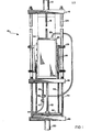
- the package forming apparatus 10 is essentially a mold in which one dimension may be varied by means of an adjustable outer mold shell 30.
- the first step in a molding operation is to lower the upper plate 62.
- the second step is raise the shell 30 to adjust box size.
- pre-expanded moldable material is charged into a mold cavity 52 defined by a mold core 54 and outer mold shell 30 through charge port 64.
- An electronic sensor 66 detects when the mold volume is filled.
- the charge port 64 is then sealed, which simultaneously seals the mold cavity 52.
- Heat is then applied to inner mold chamber 70 by means of steam which enters through steam nozzle 60.
- the steam is conveyed to the inner mold chamber 70 by means of the steam line 36.
- steam may enter the mold cavity 52 via the top mold end plate 62 which contains a plurality of steam nozzles 68 connected to a steam line 22.
- Steam lines 36 and 22 are connected to suitable steam supply and are constructed of noncorrosive flexhose which accommodates limited movement of certain mold parts. The purpose of said movements will be described hereinbelow.
- the heat supplied in the inner mold chamber 70 is conveyed to the mold cavity 52 through direct conductive heat transfer through the mold core 54 and is aided by flow of steam through conventional slotted core vents 56 which are located in holes at spaced intervals along the mold core 54.
- the beads are pre-expanded in a conventional pre-expander. Hence, the beads are large enough that they do not pass through the steam vents.
- the beads form a porous mass in the cavity permitting the steam to permeate the mass, entering through the core vents.
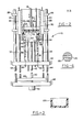
- the core vents 56 are shown in greater detail in Fig. 6. There, it is noted that the core vents 56 are of general cylindrical shape and contain narrow slots 72 which allow steam to flow from the inner mold chamber 70 to the mold cavity 52, yet prevent the moldable material, described hereinbelow, from passing from the mold cavity 52 into the inner mold chamber 70. In all, the embodiment of the invention which is shown in the drawing may contain for example about 1,000 core vents.
- the moldable material used to make the container is of the general class of polymeric materials known as thermoplastics.
- thermoplastic polymers which may be used as moldable material are nylon, nitrile resins such as ABS terpolymer or other nitrile copolymers, those ionomers such as sodium or zinc salts of ethylene/methacrylic acid copolymers which exhibit thermoplastic properties, polypropylene and copolymers thereof, polyethylene and its copolymers, thermoplastic polyesters, and homopolymers and copolymers of polystyrene, with polystyrene being preferred.
- the particular type of thermoplastic polymer which is used as moldable material would, of course, be dictated by the particular application. The choice would depend in part on the physical properties required of the container, cost, and in the case of food containers, toxicity.
- the pre-expanded moldable material used may be in the form of small spheres or other shapes amenable to pouring or passing through the charge port 64.
- the pre-expanded moldable material may be conveyed to the mold cavity 52 by means of a conventional automatic conveyance system, such as an air blown system, in which case the shape of the pre-expanded moldable material is partially dictated by the needs of the conveyor system.
- the pre-expanded moldable material is heated to conventional temperatures, it fuses to form the desired container.
- Conventional moldable material is used in known manners.
- the mold is then cooled down by means of air and water injected into the inner mold chamber 70.
- the air and water injection nozzle 59 is located in the adjustable mold end plate 58 and connects to a suitable supply line 61.
- Both heating and cooling cycles are usually determined by a timer.
- the pressure sensing device 66 is located in the top mold end plate to sense the pressure in the mold cavity 52. As the mold is heated, the pre-expanded moldable material in the mold cavity 52 expands further and thereby causes an increase in pressure which is recorded by the pressure sensing device 66. When this pressure has been maintained for a given period of time, the cooling cycle begins. During the cooling cycle the expanded moldable material, now bonded together, ; contracts, thereby relieving the pressure initially caused by the heating of the mold. When a sufficient drop in pressure is recorded by the-pressure sensor, the cooling cycle is terminated and the formed container is ready for removal.
- Product removal involves raising the mold end plate 62 by means of its suitable control cylinder '12 and piston rod 16.
- the mold end plate 62 can be moved sufficiently up out of mold 30 so that the container may be removed by sliding up over the mold core 54 and then out of the packaging apparatus 10.
- one or more air vents located in the adjustable mold end plate 58, are supplied with air that is forced into the inner mold chamber 70. This air passes out through the core vents 56 and thereby forces the molded container up off of the mold core 54 to permit removal of the one end molded container 100 from the mold.
- a feature of the invention is that the length of the container may be varied by movement of the adjustable outer mold shell 30 up and down upon the length of the mold core 54.
- the effect of this movement can be seen by a comparison of Figs. 2 and 5.
- Fig. 2 shows the molding apparatus 10 being operated when adjustable outer mold shell 30 is in an upper position. Only a part of the full length of the mold core 54 is thus being utilized.
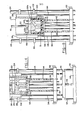
- Fig. 4 by contrast, the adjustable outer mold shell 30 has been moved further upward by means of a piston rod 42 which is operated by a hydraulic cylinder 50. Now it is observed that a portion of the mold core 54 is not being used to form a part of the molded container, as only the upper end 70 of the mold core is being utilized.
- the adjustable mold end plate 58 and the outer mold 30 are a unit and move as such.
- the mold cavity bottom ring or seal 31 which forms the mold-closure for the lower edge of the mold cavity and of the container, moves as a unit with the other two pieces.
- the only parts of the mold which do not move with piston rod 42 are the mold core 54 and the mold end plate 62.
- the mating surfaces of the pieces which are slidably adjustable in relation to each other are of sufficient tolerance so that an adequate seal is maintained between the fixed and the slidable portions of the mold and any conventional seals may be used, as desired.
- the seals of the mold end plate 60 enable it to be moved out of the mold shell 30 and back into it readily and permit air and steam to escape from the mold cavity.
- the novel adjustment feature operates as follows: once the length of the container to be preoduced has been determined, the hydraulic cylinder 50 is operated so as to correctly associate or position the movable parts of the mold. Slidably connected to the hydraulic cylinder 50 is the piston rod 42 which moves up or down in response to the pressure applied to said hydraulic cylinder. As can be seen in reference to Figs. 2 and 4, the outer mold shell 30 and adjustable mold end plate 58 are secured to piston rod 42 either directly or by suitable interconnection. The outer mold or shell 30 is rigidly secured to spacer blocks 28 by suitable means, which spacer blocks 38 connect to a tie plate 46 through push rods 34. The tie plate 46 is attached to and moved by the piston rod 42.
- the adjustable mold lower end plate 58 is attached to the tie plate 46 by the piston rod 42 or an extension thereof to move in unison with the tie plate.
- the mold perimeter seal ring or piece 31 is rigidly attached to the outer mold shell 30 and is in slidable sealed contact with mold core 54.
- movement of piston rod 42 causes corresponding unitary movement of outer mold shell 30, the mold perimeter or cavity seal ring 31 and the adjustable mold end plate 58. Movement of these pieces as a unit in turn cause a corresponding increase or decrease in the length of mold cavity 52.
- the adjustable mold end plate 58 and the mold perimeter ring 31 must be in reasonably close but not air tight tolerance with mold core 54 so that air and steam can exhaust from the mold cavity during fusion heating.
- close tolerance surfaces are moved relative to one another, it is required that said surfaces be supported by a rigid base to maintain their proper alignment.
- a rigid support is maintained by base support or plate 48 that is suitably secured in a fixed position to which is affixed the hydraulic cylinder 50 and bolster plate 32, the latter by means of support posts or columns 44.
- the vertical mold or frame supports 24 in turn are affixed to the bolster plate 32 and to a similar top frame plate and thereby are also rigidly secured.
- the pillow block hearings 26 which provides slidable alignment and positioning for the mold spacer blocks 28 and the outer mold shell 30 attached thereto.
- One of the inherent advantages of the invention is that, as the adjustable mold end plate 58 moves up along the mold core 54, the core vents 56 which are thereby outside of the molding cavity 52, are cut off from the steam.
- the use of the steam is self-limiting to those core vents 56 which are still located along the reduced length of the cavity 52, and a variable size steambox is provided.
- the water and/or air used in the cooling cycle, and the air used in the demolding cycle are also limited to the operative length of the mold cavity 52.
- a drain tube can connect to the mold end plate 58.
- the mold core 54 is secured to the fixed bolster plate 32 as by cap screws 55.
- the adjustable length mold of the invention includes a frame which has top and base plates 14 and 48, mold support columns 24, the bolster plate 32, and support columns 44 all firmly and rigidly fixed together.
- the outer mold or shell 30 has mold spacer blocks 48 located on either side of the mold secured thereto and in turn they are secured to the pillow block bearing 26 which are slidably secured to the vertical supports 24.
- the pillow block bearings 26 move correspondingly up or down the vertical mold support columns 24 by rods 34 and plate 46.
- the materials of construction of the packaging apparatus 10 consists of conventional, appropriate materials, most notably steel and aluminum.
- Aluminum metal comes in direct contact with the moldable material.
- Aluminum is preferred because of its better heat transfer characteristics and lower heat capacity compared to steel, thus allowing greater ease of heat up and cooling during the processing cycle.
- those portions of the device which come in contact with the moldable material may be coated with a non-stick compound such as polytetrafluoroethylene or other material aiding in mold release.
- the core vents 56 may also be constucted of any suitable material, with aluminum or bronze being preferred. Bronze has been utilized in the embodiment shown because it is the most common conventional material used in the art.
- the steam lines 22 and 36 may connect to any common manifold or supply source. In general, extra low or high stream pressure is. utilized, the particular pressure and temperature used being determined by the particular type of moldable material being utilized to make the container.
- tie rods 34 Any suitable number of the tie rods 34 may be used and they usually are positioned in balanced relation on the tie plate 46.
- FIG. 2 shows how an adjustable length container having one open end can be made in the apparatus of the invention
- this container 100 as shown produced by the apparatus of Fig. 2 can be used in a number of different ways.
- the apparatus can be moved to the different adjusted position shown in Fig. 4 wherein the mold shell 30 is moved vertically with relation to the apparatus or frame 24 of the mold press so that the mold cavity ring 31 can be brought up into substantial horizontal alignment with the upper end 70 of the mold core.
- the axially movable top mold closure plate 62 can be removed from engagement with the mold shell-30 and molding material and/or articles to be packaged can be introduced into the open center of the mold shell 30.
- a plurality of articles to be packaged are indicated at 102 and 103 and are placed on the end 70 and the moldable powder may be introduced into the mold cavity to cover the articles. Then the beads are heated to form an enclosure in which the articles 102 and 103 are embedded. Or the moldable powders can be fed into the mold cavity through the nozzle 64 or equivalent and then have the powder fused in place to form the mass 104 of plastic packaging material in which the articles are embedded at the bottom end of such mass. Then, if desired, this mass 104 can have any suitable enclosure placed therearound or an end cover can be placed over the lower end of the packaging mass 104 and the articles would be suitable to be shipped in such condition as shown in section in Fi g . 4.
- the packaging action can be completed by use of the container 100 as made by the mold apparatus of the invention as shown in Fig. 2 and have this container 100 be placed into the mo,ld shell 30 in inverted form and have articles 102a and 103a placed therein. (Fig. 5) Thereafter the packaging material P is introduced into the open center of the container 100 and the material can be set up therein by application of heat and pressure and a steam through the top mold closure plate 62 and closure plate 70 of the mold core. Then the top closure plate 62 would be removed from engagement with the mold shell 30 by the control cylinder for the piston rod 16 and the article or container can be removed in any desired manner including application of fluid pressure through the top closure plate 70 of the mold core.
- Any suitable cover of at selectable thickness then can be suitably secured to the package Z formed in the apparatus as shown in Fig. 5 to cover the open end of the container 100.
- the beaded molding material normally fills the container 100 to its open end as shown and it is suitably fused into a mass.
- the container 100 of the invention has uniform thickness walls and the bottom of the container can be of any desired thickness depending on the spacing of the closure plate 62 from the mold core 54. Also a top cover can be made of any suitable thickness.
- the articles shown in Figs. 4 and 5 should preferably be positioned in spaced relation to the inner margins of the mold shell 30 to enable plastic moldable material fed to the mold cavity to flow around the articles and at least substantially embed the articles in the molded mass produced.
- the mold closing pressure is controlled in any conventional manner including use of the pressure sensing device 66 and the position of the mold end plate 62 may be varied to provide the desired pressure.
- the container 100 can be made of plastic of one density and then the filler block P, Fig. 5, can be made of a second density.
- the density of the container 100 can be varied by filling the mold cavity with fusable beads under a light pressure and fusing the beads under such pressure. Or, after the mold cavity is filled with beads under light pressure, the mold shell 30 and mold end plate 58 could be moved axially to compress the beads together more and fuse the beads under higher pressure.
- All of the steam of fluid supply tubes 36,61 and equivalent in the apparatus preferably extend to the plate 46 but they may be of any suitable design and construction. Portions of such tubes are omitted in Fig. 1 for clarity and the vents 56 are omitted in the holes in the mold core 54.
- the apparatus may use any suitable manual and/or automatic controls for its adjustments and molding action.
- the apparatus is not limited to adjustment of the shipping container size in only one dimension.
- the mold core 54 and the mold shell 30 are, of course, concentric.
Landscapes
- Engineering & Computer Science (AREA)
- Mechanical Engineering (AREA)
- Moulds For Moulding Plastics Or The Like (AREA)
Priority Applications (1)
| Application Number | Priority Date | Filing Date | Title |
|---|---|---|---|
| EP84300255A EP0149292A3 (de) | 1984-01-17 | 1984-01-17 | Längenregulierbare Form zum Herstellen von Behältern |
Applications Claiming Priority (1)
| Application Number | Priority Date | Filing Date | Title |
|---|---|---|---|
| EP84300255A EP0149292A3 (de) | 1984-01-17 | 1984-01-17 | Längenregulierbare Form zum Herstellen von Behältern |
Publications (2)
| Publication Number | Publication Date |
|---|---|
| EP0149292A2 true EP0149292A2 (de) | 1985-07-24 |
| EP0149292A3 EP0149292A3 (de) | 1985-08-14 |
Family
ID=8192534
Family Applications (1)
| Application Number | Title | Priority Date | Filing Date |
|---|---|---|---|
| EP84300255A Withdrawn EP0149292A3 (de) | 1984-01-17 | 1984-01-17 | Längenregulierbare Form zum Herstellen von Behältern |
Country Status (1)
| Country | Link |
|---|---|
| EP (1) | EP0149292A3 (de) |
Cited By (5)
| Publication number | Priority date | Publication date | Assignee | Title |
|---|---|---|---|---|
| EP0297196A1 (de) * | 1987-04-03 | 1989-01-04 | Chell Snc | Hohlform zur Herstellung von plastischen Gegenständen, die verschiedene Höhen und Mundstücke haben |
| FR3010345A1 (fr) * | 2013-09-06 | 2015-03-13 | Delphia | Moule destine a la fabrication d'objets par injection d'une matiere expansible |
| CN110421753A (zh) * | 2019-08-08 | 2019-11-08 | 江苏江盈家居用品有限公司 | 一种模具及模钉长度可调节的模体 |
| WO2022043801A1 (en) * | 2020-08-24 | 2022-03-03 | Deenar Shashikant Walawalkar | A mould set for fabrication of an eps pallet and use thereof |
| CN118124094A (zh) * | 2024-05-08 | 2024-06-04 | 四川新升包装科技有限责任公司 | 一种包装盒的模具 |
Family Cites Families (3)
| Publication number | Priority date | Publication date | Assignee | Title |
|---|---|---|---|---|
| US2624928A (en) * | 1948-06-21 | 1953-01-13 | Leonard D Long | Press for molding concrete building elements |
| US3170010A (en) * | 1961-12-28 | 1965-02-16 | American Can Co | Method of molding pre-expanded plastic beads |
| US3999736A (en) * | 1971-10-13 | 1976-12-28 | Kurt Salmon Associates, Inc. | Apparatus for encapsulating an article in molded polyurethane |
-
1984
- 1984-01-17 EP EP84300255A patent/EP0149292A3/de not_active Withdrawn
Cited By (6)
| Publication number | Priority date | Publication date | Assignee | Title |
|---|---|---|---|---|
| EP0297196A1 (de) * | 1987-04-03 | 1989-01-04 | Chell Snc | Hohlform zur Herstellung von plastischen Gegenständen, die verschiedene Höhen und Mundstücke haben |
| FR3010345A1 (fr) * | 2013-09-06 | 2015-03-13 | Delphia | Moule destine a la fabrication d'objets par injection d'une matiere expansible |
| CN110421753A (zh) * | 2019-08-08 | 2019-11-08 | 江苏江盈家居用品有限公司 | 一种模具及模钉长度可调节的模体 |
| WO2022043801A1 (en) * | 2020-08-24 | 2022-03-03 | Deenar Shashikant Walawalkar | A mould set for fabrication of an eps pallet and use thereof |
| AU2021331702B2 (en) * | 2020-08-24 | 2024-02-29 | Verte Technologies, LLC | A mould set for fabrication of an EPS pallet and use thereof |
| CN118124094A (zh) * | 2024-05-08 | 2024-06-04 | 四川新升包装科技有限责任公司 | 一种包装盒的模具 |
Also Published As
| Publication number | Publication date |
|---|---|
| EP0149292A3 (de) | 1985-08-14 |
Similar Documents
| Publication | Publication Date | Title |
|---|---|---|
| US4492663A (en) | Method and adjustable length mold for manufacturing a foamed packaging assembly | |
| US3162705A (en) | Method for making plastic containers | |
| JP3331521B2 (ja) | 成形用具の温度制御法 | |
| US4423000A (en) | Method for molding hollow plastic articles | |
| US6386850B1 (en) | Machine for forming molded foam cushions | |
| GB2183532A (en) | Actuating mould filling apparatus in response to a mould full sensor | |
| RU2113381C1 (ru) | Способ упаковки жидких или полужидких продуктов в контейнеры из термоформуемой пластмассы и устройство для его осуществления | |
| US3676033A (en) | Apparatus for making thermoplastic cellular products | |
| US4034054A (en) | Process for thermoforming hollow articles | |
| US3488413A (en) | Method for forming packages | |
| EP0149292A2 (de) | Längenregulierbare Form zum Herstellen von Behältern | |
| US5941054A (en) | Method for producing filled rigid containers of plastic | |
| US4758394A (en) | Method of and apparatus for forming cups of expanded resin | |
| US2789313A (en) | Plastic bottle molding machine | |
| US3145240A (en) | Injection molding of foam polymeric structures | |
| JPS56123812A (en) | Method of manufacturing molding from powdery or granular thermoplastic plastic | |
| US4883630A (en) | Method for producing hollow articles of thermoplastic materials | |
| GB2065544A (en) | Apparatus for injection moulding a preform | |
| US3200175A (en) | Method of making cups | |
| JPS60165215A (ja) | コンテナを形成するための長さを調整できるモ−ルド | |
| US2871515A (en) | Apparatus for forming articles from thermoplastic materials | |
| FI76750C (fi) | Foerpackningsfoerfarande och anordning foer genomfoerande av foerfarandet. | |
| RU2194655C1 (ru) | Способ изготовления наполненной жесткой пластмассовой тары | |
| ATE128666T1 (de) | Verfahren und vorrichtung zum herstellen eines kunststoffbehälters mit verstärkten stirnseiten. | |
| US3369273A (en) | Apparatus for extruding and filling plastic containers |
Legal Events
| Date | Code | Title | Description |
|---|---|---|---|
| PUAI | Public reference made under article 153(3) epc to a published international application that has entered the european phase |
Free format text: ORIGINAL CODE: 0009012 |
|
| PUAL | Search report despatched |
Free format text: ORIGINAL CODE: 0009013 |
|
| AK | Designated contracting states |
Designated state(s): BE DE FR GB IT LU NL |
|
| AK | Designated contracting states |
Designated state(s): BE DE FR GB IT LU NL |
|
| STAA | Information on the status of an ep patent application or granted ep patent |
Free format text: STATUS: THE APPLICATION IS DEEMED TO BE WITHDRAWN |
|
| 18D | Application deemed to be withdrawn |
Effective date: 19860415 |