EP0149353B1 - Pompes à chaleur - Google Patents
Pompes à chaleur Download PDFInfo
- Publication number
- EP0149353B1 EP0149353B1 EP84308966A EP84308966A EP0149353B1 EP 0149353 B1 EP0149353 B1 EP 0149353B1 EP 84308966 A EP84308966 A EP 84308966A EP 84308966 A EP84308966 A EP 84308966A EP 0149353 B1 EP0149353 B1 EP 0149353B1
- Authority
- EP
- European Patent Office
- Prior art keywords
- working fluid
- vapour
- heat
- pump
- face
- Prior art date
- Legal status (The legal status is an assumption and is not a legal conclusion. Google has not performed a legal analysis and makes no representation as to the accuracy of the status listed.)
- Expired
Links
Images


Classifications
-
- F—MECHANICAL ENGINEERING; LIGHTING; HEATING; WEAPONS; BLASTING
- F25—REFRIGERATION OR COOLING; COMBINED HEATING AND REFRIGERATION SYSTEMS; HEAT PUMP SYSTEMS; MANUFACTURE OR STORAGE OF ICE; LIQUEFACTION SOLIDIFICATION OF GASES
- F25B—REFRIGERATION MACHINES, PLANTS OR SYSTEMS; COMBINED HEATING AND REFRIGERATION SYSTEMS; HEAT PUMP SYSTEMS
- F25B15/00—Sorption machines, plants or systems, operating continuously, e.g. absorption type
- F25B15/004—Sorption machines, plants or systems, operating continuously, e.g. absorption type of rotary type
-
- Y—GENERAL TAGGING OF NEW TECHNOLOGICAL DEVELOPMENTS; GENERAL TAGGING OF CROSS-SECTIONAL TECHNOLOGIES SPANNING OVER SEVERAL SECTIONS OF THE IPC; TECHNICAL SUBJECTS COVERED BY FORMER USPC CROSS-REFERENCE ART COLLECTIONS [XRACs] AND DIGESTS
- Y02—TECHNOLOGIES OR APPLICATIONS FOR MITIGATION OR ADAPTATION AGAINST CLIMATE CHANGE
- Y02A—TECHNOLOGIES FOR ADAPTATION TO CLIMATE CHANGE
- Y02A30/00—Adapting or protecting infrastructure or their operation
- Y02A30/27—Relating to heating, ventilation or air conditioning [HVAC] technologies
-
- Y—GENERAL TAGGING OF NEW TECHNOLOGICAL DEVELOPMENTS; GENERAL TAGGING OF CROSS-SECTIONAL TECHNOLOGIES SPANNING OVER SEVERAL SECTIONS OF THE IPC; TECHNICAL SUBJECTS COVERED BY FORMER USPC CROSS-REFERENCE ART COLLECTIONS [XRACs] AND DIGESTS
- Y02—TECHNOLOGIES OR APPLICATIONS FOR MITIGATION OR ADAPTATION AGAINST CLIMATE CHANGE
- Y02B—CLIMATE CHANGE MITIGATION TECHNOLOGIES RELATED TO BUILDINGS, e.g. HOUSING, HOUSE APPLIANCES OR RELATED END-USER APPLICATIONS
- Y02B30/00—Energy efficient heating, ventilation or air conditioning [HVAC]
- Y02B30/62—Absorption based systems
Definitions
- This invention relates to an absorption type heat pump according to the precharacterizing portion of claim 1.
- Such a heat pump is known from the EP-A-0046112.
- absorption type heat pumps the energy input to raise the low-grade heat to a higher level is provided by heating under pressure a solution containing a vapourisable working fluid, condensing at the same higher pressure the vapour thus evolved and subsequently reabsorbing the working fluid into the solvent or absorbent.
- EP-A-0119776 publication date 26 September 1984, the disclosure in which is incorporated herein by way of reference, there is described a novel form of absorption heat pump which is of a centrifugal design and which is capable of being designed in a compact form.
- the aforementioned novel form of absorption heat pump comprises a vapour generator to which a first fluid heating medium at higher temperature is charged, i.e.
- a condenser to which a first fluid medium to be heated is charged, an evaporator to which a second fluid heating medium at a lower temperature is charged, i.e. low-grade heat input, and an absorber to which a second fluid medium to be heated is charged, through which components a working fluid is circulated, which working fluid is charged as a stronger solution thereof to the vapour generator in which vapour of the working fluid is generated and from which a depleted solution of the working fluid is discharged, which the vapour is charged to the condenser in which it is liquefied, the liquid from the condenser is charged to the evaporator where it is evaporated and the vapour from the evaporator is absorbed in the said depleted solution of the working fluid in the absorber with formation of the said stronger solution characterised in that at least one of the aforesaid components is in the form of a plurality of axially-spaced, parallel, rotatable discs through the thickness of which discs
- centrifugal absorption heat pump which has a higher coefficient of performance than the aforementioned centrifugal heat pump.
- COefficient of performance is defined by the equation:
- an absorption heat pump comprising a vapour generator to which a first fluid heating medium at a higher temperature is charged, a condenser to which a first fluid medium to be heated is charged, an absorber to which a second fluid medium to be heated is charged, and an evaporator to which a second fluid heating medium at a lower temperature is charged wherein
- the aforesaid working fluids may be identical with or different from each other, and the aforesaid- absorbents may be identical with or different from each other. It is preferred that the first and second fluid media to be heated are the same as each other and flow sequentially through the absorber and the condenser.
- the prevailing pressures in the component parts of heat pumps according to the present invention will be chosen in the light of the working fluid(s) employed therein such that the vapour(s) of the working fluid(s) may be generated adjacent appropriate disc faces.
- the pressure in a first vapour generator which receives heat from a first fluid heating medium at higher temperature is higher than the pressure in a second vapour generator which receives its heat from condensation of the vapour generated in the first vapour generator.
- the prevailing pressures may be readily calculated from inter alia the known latent heats of vapourisation of suitable working fluids and the temperature of the first fluid heating medium at higher temperature.
- heat exchange is carried out between the depleted solution of working fluid leaving the vapour generator and the stronger solution of working fluid being fed to the vapour generator; preferably such heat transfer is carried out through the thickness of one or more rotatable discs.
- Centrifugal vapour generators, condensers, evaporators and absorbers comprising one or more closely-spaced discs suitable for use in heat pumps according to the present invention are more fully described in our aforementioned European Patent Application EP-A-0119776.
- the pumping unit(s) is or are conveniently of the gear pump type mounted on the rotary shaft of the heat pump.
- Means to feed fluids to and discharge fluids from the components of heat pumps according to the present invention are provided at appropriate positions thereon.
- Drive means to rotate the rotary shaft in heat pumps according to the present invention are conveniently electric motors.
- one or more flow restriction valves are provided in heat pumps according to the present invention to maintain the pressures in the components thereof at appropriate levels.
- the working fluids which are suitable for use with heat pumps according to the present invention include those which are already known in the absorption heat pump field; as examples thereof may be mentioned the chlorofluorohydrocarbons well known as refrigerants, for example Refrigerant 124, which is mono- chlorotetrafluoroethane.
- the working fluid is used in combination with a suitable absorbent therefor, which preferably is a compound of good stability and therefore able to survive without difficulty the temperature cycles which repeated use for this purpose entails.
- Suitable absorbents include the readily-available organic absorbents for these refrigerant materials, among which may particularly be mentioned tetraglyme (otherwise identified as 2, 5, 8, 11, 14-pentaoxapentadecane).
- the combination of working fluid and absorbent should be such as to have a sufficiently high heat of solution to give the required increase in temperature to the second fluid medium to be heated at the absorber.
- the working fluid is an inorganic fluid and preferably is water.
- the absorbent is an inorganic medium, e.g. sodium hydroxide, although we do not exclude the possibility that it may be an organic medium bearing one or more suitable polar substituents.
- the first fluid heating medium at high temperature used in a heat pump according to the present invention is preferably a hot gas, e.g. the hot gas obtained on combustion of a fossil fuel, although we do not exclude the possibility that it may be a liquid at a suitable higher temperature, e.g. water from a geothermal source.
- a hot gas e.g. the hot gas obtained on combustion of a fossil fuel
- a suitable higher temperature e.g. water from a geothermal source.
- the second fluid heating medium at lower temperature used in heat pumps according to the present invention is preferably a gas, and conveniently is air at ambient temperature, although we do not exclude the possibility that it may be a liquid, e.g. water in a river or lake.
- the first and second fluid media to be heated in heat pumps according to the present invention are liquids, preferably water, and more preferably the water passes sequentially through the absorber and then the condenser.
- the aforesaid water is used in a central heating system, e.g. a domestic central heating system.
- centrifugal absorption heat pump which comprises at least
- centrifugal absorption heat pump which comprises at least
- a first working fluid e.g. water in solution in a suitable absorbent
- a second working fluid which typically is also water
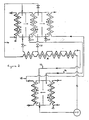
- a second working fluid is circulated, in solution in a suitable absorbent, by pump P2 through heat exchanger X21, vapour generator G2, expansion valve V21, and absorber A2 in that sequence, all of which components, together with condensers C1 and C2, heat exchanger X20 and evaporators E1 and E2, are mounted, in juxtaposition, upon a shaft for rotation therewith.
- Hot gas from a suitable burner in which a fuel, e.g. natural gas is burnt is introduced to the vapour generator G1 via line 10, and heat is transferred from the hot gas through the thickness of a rotating disc to a stronger solution of the first working fluid and first working fluid vapour is generated at high pressure.
- the vapour travels to the condenser C1 where it condenses on a first surface of each of a plurality of rotating discs with loss of heat (H1) and formation of liquid first working fluid.
- the liquid first working fluid flows via expansion valve V10, in which its pressure is reduced, heat exchanger X10 and line 11 to evaporator E1.
- the liquid first working fluid absorbs heat as it flows across a face of a rotating disc and evaporates to form a vapour.
- the vapour travels to a face of a disc in absorber A1 over which face a depleted solution of the first working fluid, obtained from vapour generator G1 via heat exchanger X11, expansion valve V11 and line 12, is flowing and in which it is absorbed to form the stronger solution of the first working fluid.
- the stronger solution of the first working fluid is then pumped by pump P1 via heat exchangers X10 and X11 and line 14 to the vapour generator G1.
- the heat evolved by absorption of the first working fluid vapour in absorber A1 passes through the thickness of the disc therein to a central heating medium, e.g. water, which flows through line 15, heat exchanger X20 and condenser C2.
- a central heating medium e.g. water
- vapour generator G2 heat H1 which has crossed the thickness of each of a plurality of rotating discs in condenser C1 to a stronger solution of the second working fluid causes vapourisation of a portion of the second working fluid and generation of vapour thereof at high pressure.
- the second working fluid vapour travels to the condenser C2 where it condenses on a surface of a rotating disc with loss of heat (H2) and formation of liquid second working fluid.
- the liquid second working fluid flows via expansion valve V20, in which its pressure is reduced, heat exchanger X20 and line 16 to evaporator E2.
- the liquid second working fluid absorbs heat as it flows across a face of a disc and evaporates to form second working fluid vapour.
- the heat is obtained from a flow of ambient air (or from some alternative ambient source of heat, e.g. water or the ground) which is fed to the second face of the disc in the evaporator E2 by line 17.
- the second working fluid vapour travels to a face of a disc in absorber A2 over which a depleted solution of the second working fluid, obtained from vapour generator G2, via heat exchanger X21, expansion valve V21 and line 18, is flowing and in which it is absorbed to form the stronger solution of the second working fluid.
- the heat evolved during the absorption passes through the thickness of the disc to the second surface thereof which is a component of evaporator E1.
- the stronger solution of the second working fluid is then pumped by pump P2 via heat exchanger X21 and line 19 to the vapour generator G2.
- the total heat input to the heat pump is the sum of the low grade heat taken from the ambient source at the evaporator E2 and the high grade heat supplied to the vapour generator G1.
- the heat output which is at a temperature intermediate that at the evaporator E2 and the vapour generator G1, is that taken up by the central heating medium in the absorber A1, heat exchanger X20 and condenser C2.
- a working fluid, in solution, is circulated by pump P through heat exchanger X, through vapour generators G1, G2 (in parallel), and absorber A1, all of which components, together with condensers C1 and C2 and evaporator E2, are mounted, in juxtaposition, upon a shaft for rotation therewith.
- a stronger solution of working fluid pumped by pump-P through heat exchanger X and line 14, is split into a first stream and a second stream which are charged to vapour generators G1 and G2 respectively.
- vapour generator G1 hot gas from a suitable burner is introduced to the vapour generator G1 via line 10 and heat is transferred from the hot gas through the thickness of a rotating disc to the first stream and working fluid vapour is generated from the first stream at high pressure.
- the working fluid vapour passes to the condenser C1 where it condenses on a first surface of each of a plurality of rotating discs with loss of heat and formation of a first liquid working fluid.
- the heat from condenser C1 crosses the thickness of said discs to the second faces thereof which form part of the vapour generator G2 and across which faces the second stream is flowing.
- Working fluid vapour is generated from the second stream at intermediate pressure.
- the vapour travels to the condenser C2 where it condenses on a first surface of a rotating disc with loss of heat and formation of a second liquid working fluid.
- Depleted solutions of working fluid from vapour generators G1 and G2 pass through expansion valves V11 and V21, and then together through at least a part of heat exchanger X and line 12 to absorber A1.
- the first and second liquid working fluid from condensers C1 and C2 passes through expansion valves V10, and V20 and line 16 to evaporator E2.
- the liquid working fluid absorbs heat as it flows across the face of a disc and evaporates to form working fluid vapour.
- the heat required for evaporation is obtained from a flow of ambient air (or from some alternative ambient source of heat, e.g. water or the ground) which is fed to the second face of the disc in evaporator E2 through line 17.
- the working fluid vapour formed in evaporator E2 travels to a face of a rotating disc in absorber A1 across which face the aforesaid combined depleted solutions of working fluid are flowing.
- the vapour dissolves in the depleted solution, to form the said stronger solution of working fluid, with generation of heat.
- the heat crosses the thickness of the disc and is absorbed by a central heating medium flowing across the second face of the disc.
- the total heat input to the heat pump is the sum of the low grade heat taken from the ambient source of heat at the evaporator E2 and the high grade heat supplied to the vapour generator G1.
- the heat output which is at a temperature intermediate that at the evaporator E2 and the vapour generator G1, is that taken up by the central heating medium in the absorber A1 and condenser C2.
- a first working fluid, in solution is circulated by pump P1 through heat exchanger XII, line 14, vapour generator G1, expansion valve VII, line 12 and absorber A1.
- a second working fluid, in solution is circulated by pump P2 through heat exchanger X21, line 19, vapour generator G2, expansion valve V21, line 18 and absorber A2.
- Hot gas from a suitable burner is introduced to the vapour generator G1 via line 10 and heat is transferred from the hot gas through the thickness of a rotating disc to a stronger solution of the first working fluid and working fluid vapour is generated.
- the working fluid vapour travels to condenser C1 where it condenses on a first surface of a plurality of rotating discs with loss of heat and formation of liquid first working fluid.
- the liquid first working fluid flows via expansion valve V10, in which its pressures is reduced and line 11 to evaporator E1.
- the liquid first working fluid absorbs heat as it flows across a face of a rotating disc and evaporates to form first working fluid vapour, which heat is obtained by passing an ambient source of heat via line 17a across the second face of the rotating disc.
- the vapour travels to a face of a disc in absorber A1 over which face a depleted solution of the first working fluid, obtained from vapour generator G1 via expansion valve VII, heat exchanger X11 and line 12 is flowing and in which it is absorbed to form the stronger solution of the first working fluid.
- the stronger solution is then pumped by pump P1 via heat exchanger XII and line 14 to the vapour generator G1.
- vapour generator G2 the heat from condenser C1 causes evaporation of a stronger solution of the second working fluid.
- the vapour of the second working fluid travels to the condenser C2 where it condenses on a surface of a rotating disc with loss of heat and formation of liquid second working.fluid.
- the liquid flows via expansion valve V20 and line 16 to evaporator E2.
- the liquid second working fluid absorbs heat as it flows across a face of a rotating disc and evaporates to form second working fluid vapour, which heat is obtained by passing an ambient source of heat via line 17 across the second face of the rotating disc.
- the second working fluid vapour passes to a face of a disc in absorber A2 over which a depleted solution of the second working fluid, obtained from vapour generator G2 via expansion valve V21, heat exchanger X21 and line 18 is flowing and in which it is absorbed, with evolution of heat, to form the stronger solution of the second working fluid.
- the heat evolved passes to the central heating medium flowing across the second face of the disc.
- the stronger solution of the second working fluid is then pumped by pump P2 via heat exchanger 21 and line 19 to vapour generator G2.
- the total heat input to the pump is the sum of the low grade heat taken from the ambient sources of heat at the evaporators E1 and E2 and the high grade heat supplied to the vapour generator G1.
- the heat output is that taken up by the central heating medium in absorbers A1 and A2 and condenser C2.
- the Figure 2 embodiment has the advantage of simplicity (one fluid pair and one evaporator) and the disadvantages of high operating temperatures and pressures in vapour generator G1; and (b) the Figure 3 embodiment has the advantage that different working fluid/ absorbent pairs can be chosen to reduce the pressure in the vapour generators/condensers and the disadvantage that it is mechanically more complex (two evaporators/absorbers are required).
- the flow of the various fluids through the components of the illustrated pumps is such that liquids, both neat and solutions, tend to flow radially outwards and vapours radially inwards in each of the rotary components thereof.
- the stronger solution of working fluid flows away from the centre of the discs to the radially outer perimeter thereof whilst evolution of vapour takes place and the depleted solution is discharged at or adjacent the radially outer perimeter of the discs;
- the liquid working fluid formed by condensation of vapour on the discs of the condensers is discharged therefrom at or adjacent the radially outer perimeter thereof; in the absorbers, working fluid vapour and the depleted solution are charged to the discs at or adjacent the centre thereof and the stronger solution is discharged therefrom at or adjacent the radially outer perimeter thereof;
- the evaporators liquid working fluid charged to the discs at or adjacent the centre thereof vapourises as it flows radially outwards across the faces of the discs.
- the illustrated heat pumps are symmetrical about their axes and are largely formed of a series of assorted discs and annular plates of varying profiles.
- the discs and annular plates may be formed by stamping sheet metal and the heat pumps may be assembled by stacking the discs and annular plates in appropriate sequence about a tubular conduit which forms the axial supportfor the structure and which also serves to conduct a central heating medium, e.g. water, through the heat pumps.
- a central heating medium e.g. water
Landscapes
- Engineering & Computer Science (AREA)
- Physics & Mathematics (AREA)
- Mechanical Engineering (AREA)
- Thermal Sciences (AREA)
- General Engineering & Computer Science (AREA)
- Sorption Type Refrigeration Machines (AREA)
- Central Heating Systems (AREA)
- Reciprocating Pumps (AREA)
- Control Of The Air-Fuel Ratio Of Carburetors (AREA)
- Compression-Type Refrigeration Machines With Reversible Cycles (AREA)
- Structures Of Non-Positive Displacement Pumps (AREA)
Claims (9)
Priority Applications (1)
| Application Number | Priority Date | Filing Date | Title |
|---|---|---|---|
| AT84308966T ATE39565T1 (de) | 1984-01-06 | 1984-12-20 | Waermepumpen. |
Applications Claiming Priority (2)
| Application Number | Priority Date | Filing Date | Title |
|---|---|---|---|
| GB8400324 | 1984-01-06 | ||
| GB848400324A GB8400324D0 (en) | 1984-01-06 | 1984-01-06 | Heat pumps |
Publications (3)
| Publication Number | Publication Date |
|---|---|
| EP0149353A2 EP0149353A2 (fr) | 1985-07-24 |
| EP0149353A3 EP0149353A3 (en) | 1985-11-21 |
| EP0149353B1 true EP0149353B1 (fr) | 1988-12-28 |
Family
ID=10554646
Family Applications (1)
| Application Number | Title | Priority Date | Filing Date |
|---|---|---|---|
| EP84308966A Expired EP0149353B1 (fr) | 1984-01-06 | 1984-12-20 | Pompes à chaleur |
Country Status (11)
| Country | Link |
|---|---|
| US (1) | US4656839A (fr) |
| EP (1) | EP0149353B1 (fr) |
| JP (1) | JPS60159569A (fr) |
| AT (1) | ATE39565T1 (fr) |
| AU (1) | AU571298B2 (fr) |
| CA (1) | CA1272609A (fr) |
| DE (1) | DE3475827D1 (fr) |
| DK (1) | DK163893C (fr) |
| GB (1) | GB8400324D0 (fr) |
| NO (1) | NO161823C (fr) |
| NZ (1) | NZ210758A (fr) |
Families Citing this family (11)
| Publication number | Priority date | Publication date | Assignee | Title |
|---|---|---|---|---|
| FR2624266B1 (fr) * | 1987-12-07 | 1990-04-20 | Armines | Installation de climatisation par absorption |
| US5598721A (en) * | 1989-03-08 | 1997-02-04 | Rocky Research | Heating and air conditioning systems incorporating solid-vapor sorption reactors capable of high reaction rates |
| US5360057A (en) * | 1991-09-09 | 1994-11-01 | Rocky Research | Dual-temperature heat pump apparatus and system |
| GB9521083D0 (en) * | 1995-10-14 | 1995-12-20 | Interotex Eeig | Heat pumps |
| US5826436A (en) * | 1996-09-03 | 1998-10-27 | Mainstream Engineering Corporation | Additive for improving performance and cooling capacity of vapor compression systems |
| US6237357B1 (en) * | 1999-06-07 | 2001-05-29 | Mitsubishi Heavy Industries, Ltd. | Vehicular air conditioner using heat pump |
| US8234876B2 (en) | 2003-10-15 | 2012-08-07 | Ice Energy, Inc. | Utility managed virtual power plant utilizing aggregated thermal energy storage |
| KR20100121616A (ko) * | 2008-02-15 | 2010-11-18 | 아이스 에너지, 인크. | 다수의 냉매 및 공통 증발기 코일을 갖춘 냉각 루프를 이용하는 열에너지 저장 및 냉각 시스템 |
| US20090293507A1 (en) * | 2008-05-28 | 2009-12-03 | Ice Energy, Inc. | Thermal energy storage and cooling system with isolated evaporator coil |
| JP2014535253A (ja) | 2011-05-26 | 2014-12-25 | アイス エナジー テクノロジーズ インコーポレーテッド | 統計的配電制御を用いたグリッド効率向上のためのシステムおよび装置 |
| US9212834B2 (en) | 2011-06-17 | 2015-12-15 | Greener-Ice Spv, L.L.C. | System and method for liquid-suction heat exchange thermal energy storage |
Citations (1)
| Publication number | Priority date | Publication date | Assignee | Title |
|---|---|---|---|---|
| US3347059A (en) * | 1964-01-22 | 1967-10-17 | Laing Nikolaus | Heat pump |
Family Cites Families (15)
| Publication number | Priority date | Publication date | Assignee | Title |
|---|---|---|---|---|
| US2196911A (en) * | 1935-10-28 | 1940-04-09 | Servel Inc | System for heating and refrigeration |
| GB523627A (en) * | 1939-01-11 | 1940-07-18 | Guido Maiuri | Improvements in absorption refrigerating machines |
| US2350115A (en) * | 1940-05-25 | 1944-05-30 | Katzow Abram | Refrigerating system |
| US2559217A (en) * | 1949-04-01 | 1951-07-03 | Cons Edison Company | Air-conditioning apparatus |
| US3483710A (en) * | 1968-06-13 | 1969-12-16 | Crane Co | Cascade absorption refrigeration system |
| US3740966A (en) * | 1971-12-17 | 1973-06-26 | Dynatherm Corp | Rotary heat pump |
| DE2624147A1 (de) * | 1976-05-28 | 1977-12-08 | Dieter Ohrendorf | Waermepumpenheizvorrichtung |
| GB2076304B (en) * | 1980-05-26 | 1984-02-22 | Univ Sydney | Heat exchange (evaporator) device |
| EP0046112B1 (fr) * | 1980-08-11 | 1986-02-26 | Etablissement Public dit: CENTRE NATIONAL DE LA RECHERCHE SCIENTIFIQUE (CNRS) | Dispositif et systèmes pour la revalorisation d'énergie thermique à bas niveau mettant en oeuvre des phénomènes d'évaporation et de mélange de deux fluides en équilibre de pression de vapeur sous des températures différentes |
| US4442677A (en) * | 1980-11-17 | 1984-04-17 | The Franklin Institute | Variable effect absorption machine and process |
| DE3113063A1 (de) * | 1981-04-01 | 1982-10-14 | Dürr Innovation GmbH, 7000 Stuttgart | Vorrichtung zur erhoehung der temperatur eines waermetraegers auf der grundlage von absorption und austreibung, verdampfung und verfluessigung eines kaeltemittels |
| JPS588961A (ja) * | 1981-07-10 | 1983-01-19 | 株式会社日立製作所 | 吸収式ヒ−トポンプ |
| US4441332A (en) * | 1982-12-06 | 1984-04-10 | Gas Research Institute | Absorption refrigeration and heat pump system |
| GB8308135D0 (en) * | 1983-03-24 | 1983-05-05 | Ici Plc | Centrifugal heat pump |
| GB8308137D0 (en) * | 1983-03-24 | 1983-05-05 | Ici Plc | Compression-type heat pumps |
-
1984
- 1984-01-06 GB GB848400324A patent/GB8400324D0/en active Pending
- 1984-12-20 AT AT84308966T patent/ATE39565T1/de not_active IP Right Cessation
- 1984-12-20 DE DE8484308966T patent/DE3475827D1/de not_active Expired
- 1984-12-20 EP EP84308966A patent/EP0149353B1/fr not_active Expired
- 1984-12-28 AU AU37217/84A patent/AU571298B2/en not_active Expired
-
1985
- 1985-01-04 NO NO850054A patent/NO161823C/no unknown
- 1985-01-04 NZ NZ210758A patent/NZ210758A/en unknown
- 1985-01-04 CA CA000471560A patent/CA1272609A/fr not_active Expired - Lifetime
- 1985-01-04 DK DK004885A patent/DK163893C/da not_active IP Right Cessation
- 1985-01-07 JP JP60000249A patent/JPS60159569A/ja active Granted
- 1985-01-07 US US06/689,190 patent/US4656839A/en not_active Expired - Lifetime
Patent Citations (1)
| Publication number | Priority date | Publication date | Assignee | Title |
|---|---|---|---|---|
| US3347059A (en) * | 1964-01-22 | 1967-10-17 | Laing Nikolaus | Heat pump |
Also Published As
| Publication number | Publication date |
|---|---|
| NO161823B (no) | 1989-06-19 |
| GB8400324D0 (en) | 1984-02-08 |
| NO850054L (no) | 1985-07-08 |
| AU3721784A (en) | 1985-07-11 |
| DK4885A (da) | 1985-07-07 |
| EP0149353A2 (fr) | 1985-07-24 |
| DK163893B (da) | 1992-04-13 |
| US4656839A (en) | 1987-04-14 |
| JPH0557503B2 (fr) | 1993-08-24 |
| JPS60159569A (ja) | 1985-08-21 |
| DK4885D0 (da) | 1985-01-04 |
| DE3475827D1 (en) | 1989-02-02 |
| AU571298B2 (en) | 1988-04-14 |
| EP0149353A3 (en) | 1985-11-21 |
| ATE39565T1 (de) | 1989-01-15 |
| NZ210758A (en) | 1987-02-20 |
| NO161823C (no) | 1989-09-27 |
| CA1272609A (fr) | 1990-08-14 |
| DK163893C (da) | 1992-09-07 |
Similar Documents
| Publication | Publication Date | Title |
|---|---|---|
| US4442677A (en) | Variable effect absorption machine and process | |
| EP0149353B1 (fr) | Pompes à chaleur | |
| WO2012110987A1 (fr) | Dispositif de conversion d'énergie environnementale | |
| NO161641B (no) | Fremgangsmaate for mekanisk kraftgenerering. | |
| AU2019406286B2 (en) | Heat pump apparatus and district heating network comprising a heat pump apparatus | |
| US4512394A (en) | Variable effect absorption machine and process | |
| US4553408A (en) | Centrifugal heat pump | |
| US20260077302A1 (en) | Water removal system including an absorption chiller system and a heat pump system | |
| JPH10274010A (ja) | バイナリー発電システム | |
| US4793154A (en) | Centrifugal heat pump | |
| US4143517A (en) | Thermal engine | |
| EP0945691A2 (fr) | Système frigorifique à absorption avec couplage de condensat et de solution | |
| US4429662A (en) | Method and apparatus for generating vapor | |
| RU2129661C1 (ru) | Паросиловой двигатель (варианты) | |
| GB2241774A (en) | A rotary absorption cycle heat machine | |
| JPH02106665A (ja) | 吸収式ヒートポンプサイクルを利用したコ・ゼネレーションシステム | |
| US1961785A (en) | Heat cycle | |
| JPH10311207A (ja) | 水銀発電装置 | |
| JPS5947234B2 (ja) | 軸方向遠心推力をもつ熱媒体密封式熱伝達装置及び熱交換器 | |
| RU2086875C1 (ru) | Способ бесконтактной передачи тепла | |
| English | Heat operated air-conditioning and heat pump research | |
| Simmons et al. | A SOLAR-DRIVEN AMMONIA-WATER ABSORPTION AIR CONDITIONER | |
| FLUIDIZED | MACHINE INSTALLATION FOR A HEAT PUMPING PLANT | |
| JPH10274009A (ja) | バイナリー発電システムおよびその制御方法 | |
| JPS6125983B2 (fr) |
Legal Events
| Date | Code | Title | Description |
|---|---|---|---|
| PUAI | Public reference made under article 153(3) epc to a published international application that has entered the european phase |
Free format text: ORIGINAL CODE: 0009012 |
|
| AK | Designated contracting states |
Designated state(s): AT BE CH DE FR GB IT LI NL SE |
|
| PUAL | Search report despatched |
Free format text: ORIGINAL CODE: 0009013 |
|
| AK | Designated contracting states |
Designated state(s): AT BE CH DE FR GB IT LI NL SE |
|
| 17P | Request for examination filed |
Effective date: 19860405 |
|
| 17Q | First examination report despatched |
Effective date: 19861009 |
|
| D17Q | First examination report despatched (deleted) | ||
| GRAA | (expected) grant |
Free format text: ORIGINAL CODE: 0009210 |
|
| AK | Designated contracting states |
Kind code of ref document: B1 Designated state(s): AT BE CH DE FR GB IT LI NL SE |
|
| REF | Corresponds to: |
Ref document number: 39565 Country of ref document: AT Date of ref document: 19890115 Kind code of ref document: T |
|
| ITF | It: translation for a ep patent filed | ||
| REF | Corresponds to: |
Ref document number: 3475827 Country of ref document: DE Date of ref document: 19890202 |
|
| ET | Fr: translation filed | ||
| PLBE | No opposition filed within time limit |
Free format text: ORIGINAL CODE: 0009261 |
|
| STAA | Information on the status of an ep patent application or granted ep patent |
Free format text: STATUS: NO OPPOSITION FILED WITHIN TIME LIMIT |
|
| 26N | No opposition filed | ||
| ITTA | It: last paid annual fee | ||
| PGFP | Annual fee paid to national office [announced via postgrant information from national office to epo] |
Ref country code: AT Payment date: 19931111 Year of fee payment: 10 |
|
| PGFP | Annual fee paid to national office [announced via postgrant information from national office to epo] |
Ref country code: SE Payment date: 19931116 Year of fee payment: 10 |
|
| PGFP | Annual fee paid to national office [announced via postgrant information from national office to epo] |
Ref country code: CH Payment date: 19931117 Year of fee payment: 10 |
|
| PGFP | Annual fee paid to national office [announced via postgrant information from national office to epo] |
Ref country code: BE Payment date: 19931129 Year of fee payment: 10 |
|
| PGFP | Annual fee paid to national office [announced via postgrant information from national office to epo] |
Ref country code: NL Payment date: 19931231 Year of fee payment: 10 |
|
| PG25 | Lapsed in a contracting state [announced via postgrant information from national office to epo] |
Ref country code: AT Effective date: 19941220 |
|
| PG25 | Lapsed in a contracting state [announced via postgrant information from national office to epo] |
Ref country code: SE Effective date: 19941221 |
|
| PG25 | Lapsed in a contracting state [announced via postgrant information from national office to epo] |
Ref country code: LI Effective date: 19941231 Ref country code: CH Effective date: 19941231 Ref country code: BE Effective date: 19941231 |
|
| EAL | Se: european patent in force in sweden |
Ref document number: 84308966.5 |
|
| BERE | Be: lapsed |
Owner name: IMPERIAL CHEMICAL INDUSTRIES P.L.C. Effective date: 19941231 |
|
| PG25 | Lapsed in a contracting state [announced via postgrant information from national office to epo] |
Ref country code: NL Effective date: 19950701 |
|
| REG | Reference to a national code |
Ref country code: CH Ref legal event code: PL |
|
| NLV4 | Nl: lapsed or anulled due to non-payment of the annual fee |
Effective date: 19950701 |
|
| EUG | Se: european patent has lapsed |
Ref document number: 84308966.5 |
|
| REG | Reference to a national code |
Ref country code: GB Ref legal event code: IF02 |
|
| REG | Reference to a national code |
Ref country code: GB Ref legal event code: 732E |
|
| REG | Reference to a national code |
Ref country code: FR Ref legal event code: CA |
|
| PGFP | Annual fee paid to national office [announced via postgrant information from national office to epo] |
Ref country code: FR Payment date: 20031110 Year of fee payment: 20 |
|
| PGFP | Annual fee paid to national office [announced via postgrant information from national office to epo] |
Ref country code: GB Payment date: 20031118 Year of fee payment: 20 |
|
| PGFP | Annual fee paid to national office [announced via postgrant information from national office to epo] |
Ref country code: DE Payment date: 20031125 Year of fee payment: 20 |
|
| PG25 | Lapsed in a contracting state [announced via postgrant information from national office to epo] |
Ref country code: GB Free format text: LAPSE BECAUSE OF EXPIRATION OF PROTECTION Effective date: 20041219 |
|
| REG | Reference to a national code |
Ref country code: GB Ref legal event code: PE20 |