EP0149406A2 - Spritzmaschine zum Beschichten von Käsen oder ähnlichen Artikeln - Google Patents
Spritzmaschine zum Beschichten von Käsen oder ähnlichen Artikeln Download PDFInfo
- Publication number
- EP0149406A2 EP0149406A2 EP84420210A EP84420210A EP0149406A2 EP 0149406 A2 EP0149406 A2 EP 0149406A2 EP 84420210 A EP84420210 A EP 84420210A EP 84420210 A EP84420210 A EP 84420210A EP 0149406 A2 EP0149406 A2 EP 0149406A2
- Authority
- EP
- European Patent Office
- Prior art keywords
- cheese
- station
- chain
- cheeses
- machine according
- Prior art date
- Legal status (The legal status is an assumption and is not a legal conclusion. Google has not performed a legal analysis and makes no representation as to the accuracy of the status listed.)
- Withdrawn
Links
Images


Classifications
-
- B—PERFORMING OPERATIONS; TRANSPORTING
- B65—CONVEYING; PACKING; STORING; HANDLING THIN OR FILAMENTARY MATERIAL
- B65G—TRANSPORT OR STORAGE DEVICES, e.g. CONVEYORS FOR LOADING OR TIPPING, SHOP CONVEYOR SYSTEMS OR PNEUMATIC TUBE CONVEYORS
- B65G37/00—Combinations of mechanical conveyors of the same kind, or of different kinds, of interest apart from their application in particular machines or use in particular manufacturing processes
- B65G37/02—Flow-sheets for conveyor combinations in warehouses, magazines or workshops
-
- A—HUMAN NECESSITIES
- A01—AGRICULTURE; FORESTRY; ANIMAL HUSBANDRY; HUNTING; TRAPPING; FISHING
- A01J—MANUFACTURE OF DAIRY PRODUCTS
- A01J27/00—After-treatment of cheese; Coating of cheese
- A01J27/02—Devices for coating of cheese
-
- B—PERFORMING OPERATIONS; TRANSPORTING
- B05—SPRAYING OR ATOMISING IN GENERAL; APPLYING FLUENT MATERIALS TO SURFACES, IN GENERAL
- B05B—SPRAYING APPARATUS; ATOMISING APPARATUS; NOZZLES
- B05B13/00—Machines or plants for applying liquids or other fluent materials to surfaces of objects or other work by spraying, not covered by groups B05B1/00 - B05B11/00
- B05B13/02—Means for supporting work; Arrangement or mounting of spray heads; Adaptation or arrangement of means for feeding work
- B05B13/0221—Means for supporting work; Arrangement or mounting of spray heads; Adaptation or arrangement of means for feeding work characterised by the means for moving or conveying the objects or other work, e.g. conveyor belts
- B05B13/0235—Means for supporting work; Arrangement or mounting of spray heads; Adaptation or arrangement of means for feeding work characterised by the means for moving or conveying the objects or other work, e.g. conveyor belts the movement of the objects being a combination of rotation and linear displacement
Definitions
- the present invention relates to a machine for spraying a finishing product on cheeses or articles of similar shape having the same problems.
- machines capable of ensuring the application of a paint or other coating on a succession of flat parts carried by a transporter.
- These machines generally include a spray booth containing one or more spray guns which come into action at the moment when a part passes through their area of action. The parts thus treated then pass through a dryer and are finally evacuated.
- the invention aims to make it possible to establish a machine of the kind in question which solves the above problem.
- the conveyor is constituted by a chain of known type, arranged with its articulation axes oriented vertically, and which carries a succession of horizontal plates or "turners", mounted on it with free rotation, these turners having a diameter smaller than that of the cheeses to be treated.
- the axis of each tourette extends downward and is secured to a friction wheel capable of coming into contact with a corresponding rail provided in the projection booth so as to rotate the cheese on itself for that it receives the sprayed product.
- the conveyor belt of the machine has been illustrated in the form of a single line 1.
- stations 2 and 5 operate once in two, that is to say that the first loads a cheese on one of the supports or "spinner" carried by the chain, then lets a spinner pass freely , then loads the next one, etc ...
- station 5 unloads one out of two towers that pass in front of it.
- Fig. 2 to 4 show the detail of the chain and the spindles it carries.
- it is a conventional chain with vertical articulation axes comprising rollers 9 connected to each other in rotation by flat links 10, being noted (fig. 3) that the diameter of the first 3 is a little greater than the width of the second 10.
- the articulation axis 11 of a roll on two extends on the one hand upwards to carry a plate 12, which constitutes what has been called higher the turn, on the other hand down to be rigidly secured to a wheel 13 with knurled periphery.
- each of the upper links corresponding to the maximum width (or height) of the chalne (links referenced 10 ') is integral with bosses 14 in each of which is mounted for rotation an axis 15 terminated by two lateral rollers 16.
- the link lower which is below the aforementioned link 10 ' is reinforced thickness.
- Fig. 4 shows how the chain guide thus produced is established.
- the spacing between the vertical sails facing these rails is slightly greater than the diameter of the rollers 9 which can therefore circulate freely in the intermediate space thus delimited by rolling against one or the other of said sails if necessary.
- the rollers 16 roll on the upper wing of the rails while supporting the weight of the chain and the cheeses it can carry.
- the towers 12 run well above the rails and the knurled wheels 13 well below.
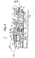
- FIG. 5 is therefore an elevational view with partial section in the vertical plane of the arrow 7 in FIG. 1 and fig. 6 the corresponding plan view.
- fig. 6 we see the chain 1 which arrives at the station according to arrow 19, which is wound there by 90 ° around a corresponding toothed wheel 20 carried by the base 21 of the station, and which departs in a straight line as indicated by the arrow 22.
- the wheel 20 has semicircular notches to receive the rollers 9. It is integral in rotation with a lower gear wheel 23 (fig.
- the underside of the yoke 29 is secured to two feet 31 which are fixed to it at two points diametrically opposite one another. Each of these feet carries at the end a caster 32 which comes to roll on a cam 33 closed on itself and which surrounds the shaft 25, this cam being supported by a hollow cylindrical part 34 fixed to the raised extension 21a of the base 21.
- Fig. 11 shows in the form of two graphs Aa, Ba, Ca and Ab, Bb, Cb the opposite vertical displacements that the cam 33 imposes on the elementary forks 30a and 30b as a function of the angle of rotation of the shaft 25. If the the curve 30a is followed, taking as starting point zero (point Aa) the position corresponding to fig. 5 and 6, it can be seen that this fork 30a is then in the high position. She received suitable feeding device, not detailed, a cheese 34 (indicated in broken lines in FIG. 5 only) with a diameter clearly greater than its total width. The fork 30b is on the contrary in the low position.
- the two forks move vertically in opposite directions; 30a descends to arrive in the low position around 135 °. Things are regulated in such a way that during this descent the fork 30a come and surround a spinner 12 of the chain 1 a bit like the way a hollow of teeth on a gear wheel surrounds a tooth on the other wheel.
- the fork 30a thus deposits the cheese on this turret which, turning around the wheel 20, releases it from the fork and drives it towards the cabin 3.
- the elementary fork 30b receives a new cheese of the feeding device. If the cam is correctly profiled, the cheese is perfectly centered on the tourette.
- the wheel 20 has eight teeth. As a spinner 12 is provided for every two links (see fig. 2), the development of this wheel 20 corresponds to four spindles. For its part, the double fork 30 is roughly comparable to a gear with two opposite toothed recesses with two intermediate empty spaces. The wheels 20 and 24 having the same pitch diameter, synchronism is achieved and the station described therefore ensures the loading of one turret out of two, the other intersecting the axis of symmetry of the station (axis corresponding to the arrow 7 in fig 6) at the moment when the double fork 30 is oriented transversely to this axis.
- a preferred solution consists in bringing the cheeses to be treated on a roller conveyor oriented perpendicular to the arrow 7 in FIG. 1 and 6 and to stop them by a stop arranged so that the first of them is exactly centered on the path corresponding thereto.
- a push cylinder oriented along arrow 7, pushes this cheese onto said fork.
- the unloading station 5 of fig. 1 is strictly identical to that of loading 2, but it works in reverse as well as this is simple to explain.
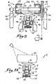
- Fig. 7 to 9 indicate the details of the turning station 6 of fig. 1. It comprises a shaft 36 carried by bearings 37 mounted on suitable supports 38. On this shaft is wedged a pulley 39 which a belt 40 connects to a geared motor 41 arranged, for example by means of a pulley adjustable and electronic circuits associated with appropriate detectors, so that each start it turns said shaft exactly half a turn.
- the shaft 36 carries two U-shaped fittings 42 opening towards one another and on each of the wings of which are mounted two sheets 43 each of which is cut so as to again constitute two elementary forks 43a, 43b opposite of opening greater than the diameter of a spinner 12.
- these two elementary forks are oriented along a common mean plane and carry two pairs of elementary forks arranged at a spacing one of the another equal to the thickness of a cheese 35.
- two metal ribbons 44 curved in an arc of a circle, carried by spacers 45 and which define two roughly semi-circular pockets suitable for forming stops for the cheeses, as explained below. .
- any suitable detector optical or mechanical, starts the gear motor to rotate the shaft 36 of a half-turn.
- the cheese is then lifted from the spinner 12, it is gradually turned over while being retained by one of the ribbons 44, then is lowered again to its starting level in the horizontal position.
- the speed of the gear motor 41 and the transmission ratio between it and the shaft 36 are adjusted so that the cheese is thus deposited exactly on the turret 12 from which it was lifted.
- the cabin 3 there are provided in the cabin 3 several pistols arranged one after the other and the detectors are arranged so that each of them processes only one cheese out of two (or more) who follow each other.
- the cabin contains an additional rail 46 (fig. 10), made for example of rubber or other elastic material with a high coefficient of friction, this rail being arranged so as to act in passing on the knurled wheels 13 in order to drive the successive tourettes 12 in rotation.
- this rail being arranged so as to act in passing on the knurled wheels 13 in order to drive the successive tourettes 12 in rotation.
Landscapes
- Life Sciences & Earth Sciences (AREA)
- Animal Husbandry (AREA)
- Environmental Sciences (AREA)
- Engineering & Computer Science (AREA)
- Mechanical Engineering (AREA)
- Treatment Of Fiber Materials (AREA)
- Chain Conveyers (AREA)
- Manufacturing And Processing Devices For Dough (AREA)
- Specific Conveyance Elements (AREA)
- Dairy Products (AREA)
Applications Claiming Priority (2)
| Application Number | Priority Date | Filing Date | Title |
|---|---|---|---|
| FR8320316A FR2556617B1 (fr) | 1983-12-15 | 1983-12-15 | Machine pour la pulverisation d'un produit sur des fromages ou articles de conformation similaire |
| FR8320316 | 1983-12-15 |
Publications (2)
| Publication Number | Publication Date |
|---|---|
| EP0149406A2 true EP0149406A2 (de) | 1985-07-24 |
| EP0149406A3 EP0149406A3 (de) | 1985-08-14 |
Family
ID=9295320
Family Applications (1)
| Application Number | Title | Priority Date | Filing Date |
|---|---|---|---|
| EP84420210A Withdrawn EP0149406A3 (de) | 1983-12-15 | 1984-12-17 | Spritzmaschine zum Beschichten von Käsen oder ähnlichen Artikeln |
Country Status (3)
| Country | Link |
|---|---|
| EP (1) | EP0149406A3 (de) |
| ES (1) | ES8605170A1 (de) |
| FR (1) | FR2556617B1 (de) |
Cited By (3)
| Publication number | Priority date | Publication date | Assignee | Title |
|---|---|---|---|---|
| WO1989011779A1 (fr) * | 1988-05-24 | 1989-11-30 | Hans Höllmüller Maschinenbau GmbH & Co | Machine pour traiter des objets avec un liquide de traitement |
| EP0494096A1 (de) * | 1990-12-28 | 1992-07-08 | Friesche Industriele Bedrijven B.V. | Verfahren zum Auftragen einer Schutzschicht rund um einen Käse und Vorrichtung zum Verdampfen einer Dispersionsflüssigkeit von einem Käse |
| NL1003749C2 (nl) * | 1996-08-06 | 1998-02-12 | Zuivelonderneming De Vijfheere | Werkwijze en inrichting voor het aanbrengen van een coating op een kaas. |
Family Cites Families (8)
| Publication number | Priority date | Publication date | Assignee | Title |
|---|---|---|---|---|
| GB694491A (en) * | 1950-01-31 | 1953-07-22 | Service Eng Ltd | Improvements relating to the spraying of liquids on to workpieces |
| GB783182A (en) * | 1954-05-12 | 1957-09-18 | Service Eng Ltd | Conveyer apparatus including mechanism for turning over articles |
| US2883031A (en) * | 1955-06-06 | 1959-04-21 | United States Steel Corp | Article transfer mechanism |
| US3208602A (en) * | 1964-03-11 | 1965-09-28 | Westinghouse Electric Corp | Transfer device |
| NL6508521A (de) * | 1965-07-02 | 1967-01-03 | ||
| US3976187A (en) * | 1972-04-07 | 1976-08-24 | Continental Can Company, Inc | Reciprocating pusher for transferring articles between conveyors |
| FR2310808A1 (fr) * | 1975-05-14 | 1976-12-10 | Cuvelier Christian | Procede pour peindre des objets plats et dispositif de mise en oeuvre |
| US4092953A (en) * | 1976-12-09 | 1978-06-06 | The D. L. Auld Company | Apparatus for coating glass containers |
-
1983
- 1983-12-15 FR FR8320316A patent/FR2556617B1/fr not_active Expired
-
1984
- 1984-12-15 ES ES539347A patent/ES8605170A1/es not_active Expired
- 1984-12-17 EP EP84420210A patent/EP0149406A3/de not_active Withdrawn
Cited By (3)
| Publication number | Priority date | Publication date | Assignee | Title |
|---|---|---|---|---|
| WO1989011779A1 (fr) * | 1988-05-24 | 1989-11-30 | Hans Höllmüller Maschinenbau GmbH & Co | Machine pour traiter des objets avec un liquide de traitement |
| EP0494096A1 (de) * | 1990-12-28 | 1992-07-08 | Friesche Industriele Bedrijven B.V. | Verfahren zum Auftragen einer Schutzschicht rund um einen Käse und Vorrichtung zum Verdampfen einer Dispersionsflüssigkeit von einem Käse |
| NL1003749C2 (nl) * | 1996-08-06 | 1998-02-12 | Zuivelonderneming De Vijfheere | Werkwijze en inrichting voor het aanbrengen van een coating op een kaas. |
Also Published As
| Publication number | Publication date |
|---|---|
| FR2556617A1 (fr) | 1985-06-21 |
| ES8605170A1 (es) | 1986-04-01 |
| EP0149406A3 (de) | 1985-08-14 |
| FR2556617B1 (fr) | 1987-03-27 |
| ES539347A0 (es) | 1986-04-01 |
Similar Documents
| Publication | Publication Date | Title |
|---|---|---|
| EP1984256B1 (de) | Verfahren und anlage zur montage palettierbarer produkte | |
| EP0503365B1 (de) | Angetriebener Kugeltisch zum orthogonalen Sortieren flacher Gegenstände | |
| CA2004409C (fr) | Machine, notamment encartonneuse, pour mettre automatiquement un article, en particulier un flacon, dans un etui | |
| FR2463061A1 (fr) | Appareil a separer un par un des objets, en particulier des bonbons et a les amener a une machine a emballer | |
| LU82855A1 (fr) | Procede,machine et installation pour recuperer les matieres constitutives des batteries d'accumulateurs usees,notamment le plomb | |
| CH619904A5 (de) | ||
| FR2491039A1 (fr) | Machine d'emballage | |
| EP0202148A1 (de) | Vorrichtung zum Aufrichten von Gegenständen, insbesondere Behälter mit Boden und Halsseite, z.B. Flaschen | |
| EP0039296A1 (de) | Ladevorrichtung mit manueller Bedienung zum Füllen oder Entleeren von Transportkästen für regelmässig angeordnete Gegenstände | |
| FR2607121A1 (fr) | Convoyeur a accumulation | |
| FR2559746A1 (fr) | Appareil de reception et de reorientation de produits allonges tels que des tubes de verre | |
| EP0149406A2 (de) | Spritzmaschine zum Beschichten von Käsen oder ähnlichen Artikeln | |
| FR2665150A1 (fr) | Dispositif pour le chargement ou le dechargement de caissettes. | |
| FR2826350A1 (fr) | Dispositif de transfert de supports de pile et machine d'impression comportant un tel dispositif | |
| EP0453983A1 (de) | Vorrichtung zum Auffangen aufzustapelnder Bögen in einer Maschine zur Herstellung von Verpackungen | |
| FR2801291A1 (fr) | Armoire mecanique de stockage | |
| EP0229805B1 (de) | Maschine zum automatischen einlegen von erzeugnissen in empfangszellen | |
| BE1003872A5 (fr) | Systeme de support sur voie. | |
| EP0042463A1 (de) | Selbsttätige Förderanlage | |
| FR2572360A1 (fr) | Dispositif a haute productivite pour orienter, aligner, redresser les bouteilles en verre ou autre, a partir de bouteilles amassees en vrac | |
| FR2756814A1 (fr) | Transporteur a marches souples du type "c" | |
| FR2558138A1 (fr) | Machine permettant de vider des caisses pleines de conteneurs, tels que des bouteilles et permettant le redressement et l'alignement des bouteilles chargees | |
| FR2539332A1 (fr) | Machine automatique pour la peinture au pistolet et le sechage d'articles plats, et notamment de panneaux en bois | |
| CA1091212A (fr) | Procede et installation de dechargement continu des containers de grande capacite en transport pneumatique | |
| FR2534154A1 (fr) | Machine automatique pour la peinture au pistolet et le sechage d'articles plats, et notamment de panneaux en bois |
Legal Events
| Date | Code | Title | Description |
|---|---|---|---|
| PUAI | Public reference made under article 153(3) epc to a published international application that has entered the european phase |
Free format text: ORIGINAL CODE: 0009012 |
|
| PUAL | Search report despatched |
Free format text: ORIGINAL CODE: 0009013 |
|
| AK | Designated contracting states |
Designated state(s): DE GB IT NL |
|
| AK | Designated contracting states |
Designated state(s): DE GB IT NL |
|
| 17P | Request for examination filed |
Effective date: 19860203 |
|
| 17Q | First examination report despatched |
Effective date: 19861121 |
|
| STAA | Information on the status of an ep patent application or granted ep patent |
Free format text: STATUS: THE APPLICATION IS DEEMED TO BE WITHDRAWN |
|
| 18D | Application deemed to be withdrawn |
Effective date: 19870402 |
|
| RIN1 | Information on inventor provided before grant (corrected) |
Inventor name: CHEVRET, GABRIEL |