EP0149447A2 - Procédé pour la régulation du niveau dans les lingotières de coulée continue d'une installation de coulée continue multiple et dispositif pour la mise en oeuvre de ce procédé - Google Patents
Procédé pour la régulation du niveau dans les lingotières de coulée continue d'une installation de coulée continue multiple et dispositif pour la mise en oeuvre de ce procédé Download PDFInfo
- Publication number
- EP0149447A2 EP0149447A2 EP84890242A EP84890242A EP0149447A2 EP 0149447 A2 EP0149447 A2 EP 0149447A2 EP 84890242 A EP84890242 A EP 84890242A EP 84890242 A EP84890242 A EP 84890242A EP 0149447 A2 EP0149447 A2 EP 0149447A2
- Authority
- EP
- European Patent Office
- Prior art keywords
- continuous casting
- level
- molds
- casting molds
- strands
- Prior art date
- Legal status (The legal status is an assumption and is not a legal conclusion. Google has not performed a legal analysis and makes no representation as to the accuracy of the status listed.)
- Withdrawn
Links
- 238000009749 continuous casting Methods 0.000 title claims abstract description 47
- 238000000034 method Methods 0.000 title claims abstract description 9
- 230000001360 synchronised effect Effects 0.000 claims abstract description 5
- 238000005266 casting Methods 0.000 claims description 20
- 239000000155 melt Substances 0.000 claims description 17
- 238000012806 monitoring device Methods 0.000 claims description 12
- 230000005855 radiation Effects 0.000 claims description 10
- 230000001105 regulatory effect Effects 0.000 claims description 7
- 238000001816 cooling Methods 0.000 claims description 3
- XLYOFNOQVPJJNP-UHFFFAOYSA-N water Substances O XLYOFNOQVPJJNP-UHFFFAOYSA-N 0.000 claims description 3
- 238000009434 installation Methods 0.000 claims description 2
- 238000002844 melting Methods 0.000 abstract description 4
- 230000008018 melting Effects 0.000 abstract description 4
- 239000002184 metal Substances 0.000 abstract 1
- 229910000831 Steel Inorganic materials 0.000 description 4
- 239000010959 steel Substances 0.000 description 4
- 239000000498 cooling water Substances 0.000 description 2
- 238000000605 extraction Methods 0.000 description 1
- 238000010438 heat treatment Methods 0.000 description 1
- 238000005259 measurement Methods 0.000 description 1
Images
Classifications
-
- B—PERFORMING OPERATIONS; TRANSPORTING
- B22—CASTING; POWDER METALLURGY
- B22D—CASTING OF METALS; CASTING OF OTHER SUBSTANCES BY THE SAME PROCESSES OR DEVICES
- B22D11/00—Continuous casting of metals, i.e. casting in indefinite lengths
- B22D11/16—Controlling or regulating processes or operations
- B22D11/20—Controlling or regulating processes or operations for removing cast stock
- B22D11/201—Controlling or regulating processes or operations for removing cast stock responsive to molten metal level or slag level
-
- B—PERFORMING OPERATIONS; TRANSPORTING
- B22—CASTING; POWDER METALLURGY
- B22D—CASTING OF METALS; CASTING OF OTHER SUBSTANCES BY THE SAME PROCESSES OR DEVICES
- B22D11/00—Continuous casting of metals, i.e. casting in indefinite lengths
- B22D11/14—Plants for continuous casting
- B22D11/147—Multi-strand plants
Definitions
- the invention relates to a method for regulating the fill level in continuous casting molds of a multiple continuous casting installation with at least two continuous casting molds supplied by a common distributor vessel, in particular two synchronously oscillating continuous casting molds with billet cross-section, from which strands are pulled out by means of a synchronous drive, and a device for carrying out the method.
- the invention aims to avoid these disadvantages and difficulties and has as its object to provide a method of the type according to the invention, which makes it possible to keep the fill level in the molds at the same level with a plurality of molds and still pull out synchronously for all strands to enable.
- This object is achieved according to the invention in that by observing the melt pool level in one of the continuous casting molds, deviations in the level of the melt pool level in this continuous casting mold from a desired value while changing the pull-out speed of all of the casting strands emerging from the continuous casting molds are compensated for, whereas deviations in the level of the melt pool are compensated.
- the) other continuous casting mold (s) can be regulated by changing the melt feed quantity in the (further) continuous casting mold (s).
- the invention is particularly advantageous for continuous casting plants designed as Bloom casting plants, it being possible for two blooms with a billet cross section to be cast for each Bloom strand.
- the pull-out rollers of the strand guide are expediently formed in one piece and extend over the cast strands of the continuous casting molds arranged next to one another, i.e. in other words, the rollers for pulling out a strand with a Bloom cross section can be used for pulling out two closely lying strands with a billet cross section.
- Radiation protection shields directed towards the rollers are provided, wherein a radiation protection shield is advantageously designed as a hollow water-permeable cooling plate.
- a particularly simple radiation protection shield is characterized in that a radiation protection shield is designed as a wide range of water jets.
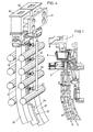
- FIG. 1 showing a partially sectioned side view of a continuous caster.
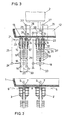
- 2 and 3 each show sections along lines II-II of FIG. 1, with FIG. 2 illustrating the equipment of the continuous casting system for blooming and FIG. 3 the equipment of the same continuous casting system for billet casting.
- Fig. 4 is a schematic perspective view of the system shown in Fig. 3.
- the continuous caster shown schematically in FIGS. 1 and 2 for the optional casting of cast strands with a (bloom) bloom block or billet cross-section has a distributor vessel 1, also referred to below as an intermediate vessel, over which a pan 2 is brought into the casting position.
- the steel entering the intermediate vessel 1 from the pan 2 and emerging from the intermediate vessel 1 passes into a plurality of molds 3, 3 ',... Arranged side by side, each of which is attached to a vertically oscillating flange 4.
- the molds 3, 3 ', ... have a preliminary block cross section.
- Each of the molds 3, 3 ', ... oscillates independently of the others and the level control for the melting bath level 6 each of the molds 3, 3 ', ... is also independent of the level controls of the other molds.
- the level control is achieved in each case by means of a stopper 9 which more or less closes or releases the pouring openings 7 of the intermediate vessel 1, into which the respective molds 3, 3 ',...
- another intermediate vessel 12 is provided for billet casting, which, as can be seen from FIG. 3, has one for each mold 10 of the two molds 10, 10 'with a cross-section of the billet has calibrated pouring nozzle 13 which passes a certain amount of steel per unit of time and flows freely into the mold.
- the respective second chill molds 10 'of the chill molds 10, 10' combined into a structural unit are supplied via a pouring tube 15 which extends below the melt pool level 14 of these chill molds 10 '.
- the two closely spaced, from the respectively to form a unit combined Koillen 10, 10 'emerging strands 16, 17 are driven with the aid of A usziehrollen 18 of the roller conveyors 5 pulled out synchronously.
- the roller conveyors 5 are in fact equipped with rollers 18, 19 which are of such a length 20 that they either have the strand with a pre-block cross-section lying in the center of the width of the roller conveyors 5 or the two extrudates 16 emerging from the molds 10, 10 'combined into one structural unit , 17 support with billet cross-section.
- the roller conveyors 5 of the strand guide therefore do not need to be replaced when changing from ingot casting to billet casting.
- Each of the molds 10, 10 'according to FIG. 3 is equipped with a level monitoring device 21, 22 for observing the height of the melt pool level 14, 23.
- level monitoring devices are known per se (DE-B - 23 5i 816, DE-C - 15 08 955); they are therefore not described in detail here.
- the level of the molten bath level 23 is regulated by changing the rate of extraction of the casting strand 16 emerging therefrom as a function of the measurement by the level monitoring device 21.
- the drive motor 24 for the driven rollers 18, shown schematically in FIG. 3 is connected to the level monitoring device 21 via a control line 25. Since the two strands 16, 17 emerging from the molds 10, 10 'which form a structural unit are pulled out synchronously - the driven rollers 16 extend over these two strands 16, 17 as described above - the level of the molten bath level 14 inevitably becomes the second Ko Kille 10 'changed by this regulation of the level of the melt pool level 23 of the first mold 10.
- the value determined by the level monitoring device 22 assigned to the second mold 10 ′ is used to control the stopper 26 regulating the inflow to this mold.
- the plug 26 can, as is shown schematically in FIG. 3, be raised or lowered in the direction of the double arrow 28 by means of a motor 27.
- the drive motor 27 is connected via a control line 29 to the run thoroughlybeobach- g s owned coupled 22nd In this way, it is possible to maintain the level of the melt pool levels 14, 23 independently of one another at the desired height, despite synchronously pulling out both strands 16, 17 in both molds 10, 10 '.
- the feed to the second mold 10 'could also be controlled by means of a slide, in which case the drive motor for the slide adjustment is coupled to the level monitoring device 22.
- the calibrated pouring nozzle 13 for the first mold 10 is expediently closable for interrupting or aborting the casting, which can be achieved by means of a plug or slide, not shown.
- this stopper or slide is not used to control the fill level, it only has to enable a shutoff of the inlet.
- the strands 16, 17 with billet cross-section emerging from the molds 10, 10 'combined into a structural unit are so closely adjacent (their distance depends solely on the thickness of the mold walls) that they would warp due to their radiant heat.
- radiation protection shields 30, 31 are provided, just below the molds 10, 10 'a first radiation protection shield 30 is formed as a wide water jet 32, which is essentially extends in the plane of symmetry 33 between the two strands 16, 17.
- the radiation protection shield 31 is implemented as a hollow, water-permeable cooling plate 34 arranged in the plane of symmetry 33.
- the flame cutting machine for cutting the strands to length is equipped with two pendulum burners when casting strands with billet cross section, so that a simultaneous division of the two strands can take place.
- each of the two molds combined to form a structural unit is provided with its own cooling water inlet and cooling water outlet which is independent of the adjacent mold.
Landscapes
- Engineering & Computer Science (AREA)
- Mechanical Engineering (AREA)
- Continuous Casting (AREA)
- Control Of Non-Electrical Variables (AREA)
Applications Claiming Priority (2)
| Application Number | Priority Date | Filing Date | Title |
|---|---|---|---|
| AT4562/83 | 1983-12-29 | ||
| AT456283 | 1983-12-29 |
Publications (2)
| Publication Number | Publication Date |
|---|---|
| EP0149447A2 true EP0149447A2 (fr) | 1985-07-24 |
| EP0149447A3 EP0149447A3 (fr) | 1986-10-22 |
Family
ID=3565611
Family Applications (1)
| Application Number | Title | Priority Date | Filing Date |
|---|---|---|---|
| EP84890242A Withdrawn EP0149447A3 (fr) | 1983-12-29 | 1984-12-13 | Procédé pour la régulation du niveau dans les lingotières de coulée continue d'une installation de coulée continue multiple et dispositif pour la mise en oeuvre de ce procédé |
Country Status (2)
| Country | Link |
|---|---|
| EP (1) | EP0149447A3 (fr) |
| JP (1) | JPS60158966A (fr) |
Cited By (7)
| Publication number | Priority date | Publication date | Assignee | Title |
|---|---|---|---|---|
| FR2569588A1 (fr) * | 1984-09-05 | 1986-03-07 | Metacon Ag | Procede de coulee continue de metal en plusieurs lignes, et dispositif pour sa mise en oeuvre |
| EP0223078A1 (fr) * | 1985-10-26 | 1987-05-27 | Metacon AG | Procédé de démarrage d'une installation de coulée continue à plusieurs lignes |
| EP1364729A3 (fr) * | 2002-05-22 | 2005-02-16 | SMS Demag AG | Procédé et dispositif pour la coulée continue de billettes rondes à partir d'un métal liquide, en particulier d'acier liquide |
| CN107900296A (zh) * | 2017-11-23 | 2018-04-13 | 燕山大学 | 伺服电机驱动的连铸结晶器非正弦振动集散控制系统 |
| US20190210099A1 (en) * | 2017-10-05 | 2019-07-11 | Emirates Steel Industries PJSC | Method for continuous casting of two or more long products using a single continuous casting strand |
| CN113523208A (zh) * | 2020-04-22 | 2021-10-22 | 中冶京诚工程技术有限公司 | 复合连铸机及其生产方法 |
| CN120205767A (zh) * | 2025-04-09 | 2025-06-27 | 江苏沙钢钢铁有限公司 | 一种连铸拉速的校验方法、装置、电子设备及存储介质 |
Families Citing this family (1)
| Publication number | Priority date | Publication date | Assignee | Title |
|---|---|---|---|---|
| JPS62183952A (ja) * | 1986-02-07 | 1987-08-12 | Sumitomo Metal Ind Ltd | 鋳型内湯面レベル制御方法 |
Family Cites Families (2)
| Publication number | Priority date | Publication date | Assignee | Title |
|---|---|---|---|---|
| CH639575A5 (de) * | 1979-04-27 | 1983-11-30 | Concast Ag | Verfahren und vorrichtung zum stranggiessen von mehreren straengen. |
| DE3029990C2 (de) * | 1980-08-08 | 1982-08-05 | Mannesmann AG, 4000 Düsseldorf | Stranggieß-Walzengerüst für Mehrstranggießanlagen zum Stranggießen von Metall, insbesondere von Stahl |
-
1984
- 1984-12-13 EP EP84890242A patent/EP0149447A3/fr not_active Withdrawn
- 1984-12-18 JP JP26955684A patent/JPS60158966A/ja active Pending
Cited By (8)
| Publication number | Priority date | Publication date | Assignee | Title |
|---|---|---|---|---|
| FR2569588A1 (fr) * | 1984-09-05 | 1986-03-07 | Metacon Ag | Procede de coulee continue de metal en plusieurs lignes, et dispositif pour sa mise en oeuvre |
| EP0223078A1 (fr) * | 1985-10-26 | 1987-05-27 | Metacon AG | Procédé de démarrage d'une installation de coulée continue à plusieurs lignes |
| EP1364729A3 (fr) * | 2002-05-22 | 2005-02-16 | SMS Demag AG | Procédé et dispositif pour la coulée continue de billettes rondes à partir d'un métal liquide, en particulier d'acier liquide |
| US20190210099A1 (en) * | 2017-10-05 | 2019-07-11 | Emirates Steel Industries PJSC | Method for continuous casting of two or more long products using a single continuous casting strand |
| CN107900296A (zh) * | 2017-11-23 | 2018-04-13 | 燕山大学 | 伺服电机驱动的连铸结晶器非正弦振动集散控制系统 |
| CN107900296B (zh) * | 2017-11-23 | 2024-05-07 | 燕山大学 | 伺服电机驱动的连铸结晶器非正弦振动集散控制系统 |
| CN113523208A (zh) * | 2020-04-22 | 2021-10-22 | 中冶京诚工程技术有限公司 | 复合连铸机及其生产方法 |
| CN120205767A (zh) * | 2025-04-09 | 2025-06-27 | 江苏沙钢钢铁有限公司 | 一种连铸拉速的校验方法、装置、电子设备及存储介质 |
Also Published As
| Publication number | Publication date |
|---|---|
| EP0149447A3 (fr) | 1986-10-22 |
| JPS60158966A (ja) | 1985-08-20 |
Similar Documents
| Publication | Publication Date | Title |
|---|---|---|
| DE3842789A1 (de) | Giessvorrichtung fuer eine zweiwalzen-stranggiessmaschine | |
| EP0028686A1 (fr) | Dispositif pour le refroidissement, notamment de barres de lingot et de billette | |
| EP0019114B1 (fr) | Procédé et dispositif pour la coulée continue de plusieurs barres | |
| EP2025432B1 (fr) | Procédé destiné à la production de produits allongés en acier par coulage en continu et laminage | |
| DE19722877C2 (de) | Flüssigkeitsgekühlte Stranggießkokille | |
| AT391643B (de) | Verfahren zum angiessen metallischer schmelze in mehrere stranggiesskokillen und vorrichtung zur durchfuehrung desselben | |
| EP0238844B1 (fr) | Procédé pour démarrer une machine de coulée continue d'acier en bande | |
| DE3247207A1 (de) | Verfahren und vorrichtung zur einstellung der konizitaet von schmalseitenwaenden von stranggiesskokillen | |
| DE3440236C2 (fr) | ||
| EP0777757B1 (fr) | Systeme de coulee par inversion avec cristallisateur | |
| EP3705202B1 (fr) | Transformation d'une installation de coulée continue pour billettes et blooms | |
| DE3440235C2 (de) | Verfahren und Vorrichtung zum Bandstranggießen von Metallen, insbesondere von Stahl | |
| EP0036611B1 (fr) | Procédé et dispositif pour soutenir une barre d'acier fabriquée par un procédé de coulée continue | |
| DE4203337C2 (de) | Verfahren zum Stranggießen von Metallen | |
| EP0005820A1 (fr) | Procédé et dispositif pour la coulée continue des métaux selon une ou plusieurs lignes de coulée | |
| EP0083916B1 (fr) | Dispositif pour la coulée continue horizontale de métaux et d'alliages, notamment d'acier | |
| DE3801932A1 (de) | Verfahren zum giessen eines stahlbandes in einer stahlbandgiessanlage | |
| AT412454B (de) | Verfahren und vorrichtung zur temperaturführung einer schmelze in einer gekühlten stranggiesskokille | |
| EP0107069A1 (fr) | Procédé pour la coulée continue de métaux, en particulier de l'acier et installations de coulée continue pour la mise en oeuvre du procédé | |
| EP2480356B1 (fr) | Procédé et dispositif pour couler une masse métallique fondue avec une machine de coulée en continu | |
| EP0560061B1 (fr) | Dispositif et procédé pour la coulée continue du métal | |
| DE4307464A1 (de) | CSP-Stranggießmaschine für die kontinuierliche Herstellung von Dünnbrammen aus Stahl | |
| AT403351B (de) | Verfahren zum stranggiessen eines metallstranges | |
| EP0151802B1 (fr) | Dispositif pour l'introduction de métal liquide, en particulier d'acier liquide dans une coquille de coulée continue | |
| DE19706151C2 (de) | Verfahren und Tauchrohr zum Metallstranggießen |
Legal Events
| Date | Code | Title | Description |
|---|---|---|---|
| PUAI | Public reference made under article 153(3) epc to a published international application that has entered the european phase |
Free format text: ORIGINAL CODE: 0009012 |
|
| AK | Designated contracting states |
Designated state(s): BE CH DE FR GB IT LI LU NL SE |
|
| RIN1 | Information on inventor provided before grant (corrected) |
Inventor name: KOCH, WILHELM, ING. |
|
| PUAL | Search report despatched |
Free format text: ORIGINAL CODE: 0009013 |
|
| AK | Designated contracting states |
Kind code of ref document: A3 Designated state(s): BE CH DE FR GB IT LI LU NL SE |
|
| STAA | Information on the status of an ep patent application or granted ep patent |
Free format text: STATUS: THE APPLICATION IS DEEMED TO BE WITHDRAWN |
|
| 18D | Application deemed to be withdrawn |
Effective date: 19870422 |
|
| RIN1 | Information on inventor provided before grant (corrected) |
Inventor name: KOCH, WILHELM, ING. |