EP0149724B1 - Verfahren und Einrichtung zur Codierung von digitalen Signalen - Google Patents
Verfahren und Einrichtung zur Codierung von digitalen Signalen Download PDFInfo
- Publication number
- EP0149724B1 EP0149724B1 EP84112041A EP84112041A EP0149724B1 EP 0149724 B1 EP0149724 B1 EP 0149724B1 EP 84112041 A EP84112041 A EP 84112041A EP 84112041 A EP84112041 A EP 84112041A EP 0149724 B1 EP0149724 B1 EP 0149724B1
- Authority
- EP
- European Patent Office
- Prior art keywords
- signal
- coefficients
- excitation
- covariance
- block
- Prior art date
- Legal status (The legal status is an assumption and is not a legal conclusion. Google has not performed a legal analysis and makes no representation as to the accuracy of the status listed.)
- Expired
Links
- 238000000034 method Methods 0.000 title claims abstract description 21
- 230000005284 excitation Effects 0.000 claims abstract description 109
- 230000015572 biosynthetic process Effects 0.000 claims abstract description 43
- 238000003786 synthesis reaction Methods 0.000 claims abstract description 43
- 230000004044 response Effects 0.000 claims abstract description 39
- 230000003044 adaptive effect Effects 0.000 claims abstract description 9
- 239000011159 matrix material Substances 0.000 claims description 19
- 238000012545 processing Methods 0.000 claims description 7
- 230000002123 temporal effect Effects 0.000 claims description 7
- 238000004364 calculation method Methods 0.000 abstract description 4
- 230000005540 biological transmission Effects 0.000 abstract description 2
- 230000003111 delayed effect Effects 0.000 abstract description 2
- 238000006243 chemical reaction Methods 0.000 description 4
- 238000005070 sampling Methods 0.000 description 3
- 238000009795 derivation Methods 0.000 description 2
- 238000012986 modification Methods 0.000 description 2
- 230000004048 modification Effects 0.000 description 2
- 238000007792 addition Methods 0.000 description 1
- 238000013459 approach Methods 0.000 description 1
- 238000010586 diagram Methods 0.000 description 1
- 230000000694 effects Effects 0.000 description 1
- 239000000284 extract Substances 0.000 description 1
- 230000000116 mitigating effect Effects 0.000 description 1
- 239000000203 mixture Substances 0.000 description 1
- 230000008447 perception Effects 0.000 description 1
- 230000001360 synchronised effect Effects 0.000 description 1
Images


Classifications
-
- G—PHYSICS
- G10—MUSICAL INSTRUMENTS; ACOUSTICS
- G10L—SPEECH ANALYSIS TECHNIQUES OR SPEECH SYNTHESIS; SPEECH RECOGNITION; SPEECH OR VOICE PROCESSING TECHNIQUES; SPEECH OR AUDIO CODING OR DECODING
- G10L19/00—Speech or audio signals analysis-synthesis techniques for redundancy reduction, e.g. in vocoders; Coding or decoding of speech or audio signals, using source filter models or psychoacoustic analysis
- G10L19/04—Speech or audio signals analysis-synthesis techniques for redundancy reduction, e.g. in vocoders; Coding or decoding of speech or audio signals, using source filter models or psychoacoustic analysis using predictive techniques
- G10L19/08—Determination or coding of the excitation function; Determination or coding of the long-term prediction parameters
- G10L19/10—Determination or coding of the excitation function; Determination or coding of the long-term prediction parameters the excitation function being a multipulse excitation
-
- G—PHYSICS
- G10—MUSICAL INSTRUMENTS; ACOUSTICS
- G10L—SPEECH ANALYSIS TECHNIQUES OR SPEECH SYNTHESIS; SPEECH RECOGNITION; SPEECH OR VOICE PROCESSING TECHNIQUES; SPEECH OR AUDIO CODING OR DECODING
- G10L19/00—Speech or audio signals analysis-synthesis techniques for redundancy reduction, e.g. in vocoders; Coding or decoding of speech or audio signals, using source filter models or psychoacoustic analysis
- G10L19/04—Speech or audio signals analysis-synthesis techniques for redundancy reduction, e.g. in vocoders; Coding or decoding of speech or audio signals, using source filter models or psychoacoustic analysis using predictive techniques
- G10L19/06—Determination or coding of the spectral characteristics, e.g. of the short-term prediction coefficients
Definitions
- the invention relates to a method and apparatus for coding of digital signals and is especially, but not exclusively, applicable to coding of voice frequency signals to reduce bit rates for reduced transmission or storage requirements.
- the invention concerns coding systems in which the input signal is encoded in discrete blocks. For each block an excitation signal is derived which, when applied to a synthesis filter having suitable coefficients, will generate an approximation to the input signal.
- the excitation signal is a train of pulses having a period corresponding to the fundamental periodicity of the input signal. This is not entirely satisfactory becaus, the decoded signal from the synthesis filter is not usually an accurate reproduction of the input signal.
- the excitation signal comprises a set of pulses having amplitudes and locations in the particular block determined according to the signal waveform.
- Each set of pulses is derived using a linear predictive coding (LPC) filter which has reflection coefficients derived from the input signal.
- LPC linear predictive coding
- Each excitation pulse is derived by calculating the filter response for every possible pulse position and selecting the one which gives least weighted error between such response and the input signal.
- the weighting of the error exploits the properties of human auditory perception.
- the calculation of the excitation pulses can only begin when the LPC coefficients for the block are available. Consequently, there is a delay, equal to at least twice the period or frame over which the LPC coefficients are derived, between the synthesizer output and the encoder input.
- Atal and Remde specify a frame period of about 20 milliseconds, equivalent to several blocks, which in their proposal, are 5 milliseconds long.
- a delay could be intolerable because of exacerbated echo problems.
- apparatus for processing a digital signal comprises an encoder having
- the apparatus may further comprise:
- the primary advantage of this arrangement is that the excitation signal calculations in the encoder are delayed by only the duration of the block. The delay therefore can be much shorter than in the previous known proposals.
- the coefficients may be derived on a sample-by-sample or continuous basis and preferably are converted to LPC coefficients.
- the coefficients generating means comprises an adaptive lattice.
- the decoder synthesis filter may then comprise a lattice too, although other filters may also be used, for example, and preferably, a recursive filter with adaptable prediction coefficients.
- a method of processing a digital signal comprises encoding the digital signal by:
- the method may further comprise decoding the output signal by:
- the first excitation pulse is derived by calculating the filter response for every possible pulse position in the block and selecting the one which gives the least weighted error when compared with the input signal. The procedure is then repeated, taking into account the contribution of the first excitation pulse, to find the next-best or second excitation pulse, and so on, until the complete set of excitation pulses have been selected.
- a disadvantage of this approach is that it requires a considerable number of operations, i.e. multiplications and additions for each set of excitation pulses.
- the encoder synthesis filter for which aid impulse response is computed is a modified synthesis filter i.e. a synthesis filter modified to take into account perceptual weighting additional to any preemphasis applied to the input signal.
- the covariance and the cross-correlation are used to derive the location of the maximum cross-correlation, which is the position of the first excitation pulse, and the corresponding amplitude of that pulse.
- the cross-correlation signal from the preceding pulse computation is used, having been stored in a buffer.
- the general covariance matrix vector corresponding to the pulse location is multiplied by the corresponding amplitude and subtracted from the stored preceding cross-correlation signal.
- the location of the maximum value of the difference a' m and corresponding pulse amplitude, are derived as before to give the parameters of the instant excitation pulse.
- the general covariance signal may be derived by:
- the general covariance matrix vector is then the matrix row corresponding to that of the maximum cross-correlation value.
- the general covariance signal is the output of an auto- correlator.
- the auto-correlation signal is used directly in computing the amplitude of the first excitation pulse.
- the difference signal is derived by subtracting from the preceding value the product of the amplitude and the auto-correlation signal R h (i).
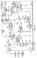
- the transmitter/encoder comprises input means 10, to which an analogue speech input signal is applied and which provides a corresponding signal So in linear PCM format.
- Each sample of the linear PCM formatted signal S " comprises 16 bits.
- This signal S " is applied to storage means 12 and coefficient signal generating means 14, respectively.
- the storage means 12 comprises a buffer which receives the signal S " serially and stores it in blocks of 32 samples. Each block has a duration of 4 ms.
- the contents of the buffer 12 are accessed by excitation signal generating means 16 which uses them to generate an excitation signal (A), which is applied to a multiplexer 18.
- This excitation signal (A) comprises a series of bits representing the amplitude and location of each of a set of pulses which, applied to a synthesis filter having suitable coefficients, will regenerate the block of the PCM input signal.
- the excitation signal (A) also includes a gain factor, (G), which will be explained later.
- the coefficient signal generating means 14 derives from the linear PCM signal S n a coefficient signal representing sets of reflection coefficients K 1 ⁇ K 8 . These coefficients are updated on a sample-by-sample basis.
- the coefficient signal from the coefficient generating means 14 is applied to the multiplexer 18 and the excitation signal generating means 16, respectively.
- the coefficient signal is updated continuously, only one set of coefficients K 1 ⁇ K 8 is used in calculating each set of excitation pulses.
- the set of coefficients used are those pertaining to the last sample period of that block. In this specific example, therefore, the coefficients are subsampled or extracted every 32 samples coinciding with the end of each block.
- the coefficient signal applied to the multiplexer 18 comprises a difference signal, specifically a series of bits which represent the difference between the instant coefficient values and those previously transmitted.
- the output of multiplexer 18 is transmitted via channel 20 to the receiver/decoder 22.
- the excitation signal A and coefficient signal K are segregated by means of a demultiplexer 24.
- the three components of the excitation signal comprising amplitude component A m , location component m, and gain factor G, are applied to decoder input means 26 wherein they are decoded by amplitude decoder 21, location decoder 23, and gain factor or r.m.s. decoder 25, respectively.
- the outputs of the amplitude decoder 21 and gain or r.m.s. decoder 25 are multiplied together by multiplier 27, the output of which is applied to excitation pulse generator 29.
- the output of the location decoder 23 is also applied to excitation pulse generator 29, which produces therefrom a train of excitation pulses P, having the appropriate amplitudes and locations. In each 4 mS period only 8 pulses will be generated. It has been found that a mere 8 pulses are sufficient to reconstruct accurately each 32 sample block of the input signal.
- the excitation pulses are applied to the input of a synthesis filter 28, which has adjustable predictor coefficients a 1 ⁇ a 8 .
- the coefficient signal K, from the demultiplexer 24 is applied to coefficient decoding means 30 which produces therefrom the reflection coefficients K 1 ⁇ K 8 .
- the adjustment of the synthesis filter coefficients is synchronised to the beginning of the 4 millisecond period during which the corresponding set of excitation pulses are applied to the input of the synthesis filter 28.
- the resulting output signal from the synthesis filter 28, following its excitation by the set of excitation pulses, is a close approximation to the corresponding 4 millisecond block of the linear PCM input signal S n from which the set of excitation pulses were derived.
- the input means 10 comprises sampling means 40 for sampling and digitizing the analogue voice signal into 8-bit ⁇ -law samples, p-law to linear conversion means 42, and pre-emphasis means 44 for emphasizing the high frequencies for perceptual reasons.
- sampling means 40 for sampling and digitizing the analogue voice signal into 8-bit ⁇ -law samples
- p-law to linear conversion means 42 for linear conversion
- pre-emphasis means 44 for emphasizing the high frequencies for perceptual reasons.
- the input means 10 could be modified readily to accommodate inputs other than analogue speech.
- the A/D sampling means 40 could be omitted if the input signal were already in PCM form.
- conversion from A-law could be used instead of p-law if the signal required it, and other weighting could be applied.
- the coefficient signal generating means 14 comprises an adaptive lattice 46 and coefficient encoder 48.
- the lattice 46 is shown in detail in Figure 4 and is of the kind disclosed by J. I. Makhoul and L. K. Cosell in a paper entitled "Adaptive Lattice Analysis of Speech". IEEE Transactions of Acoustics, Speech and Signal Processing, Vol. ASSP-29, No. 3, June 1981.
- the adaptive lattice illustrated in Figure 4 has eight stages. Its output is discarded, its prime purpose being to vary continually its coefficients K 1 ⁇ K 8 in dependence upon the linear PCM input signal S " applied to its input.
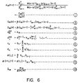
- the adaptive estimate of K m (n+1) for each stage m, where 1 ⁇ m ⁇ 8, is derived generally in accordance with equation 1, (see Figure 6) where:
- w is the impulse response of a recursive filter of finite order.
- the coefficient encoder 48 encodes the set of coefficient values (actually the difference between each set and the previously-transmitted set) every 4 milliseconds to provide the coefficient signal K, which is applied to both the multiplexer 18 and the excitation signal generating means 16.
- the coefficient signal K i is decoded by a decoder 52 which extracts the original set of reflection coefficients K 1 ⁇ K 8 .
- Conversion means 54 then transforms the reflection coefficients K 1 ⁇ K 8 into the corresponding set of predictor coefficients a 1 ⁇ a 8 , using the recursive formulae specified as equations 4 and 5 in Figure 6.
- the set of predictor coefficients a 1 ⁇ a 8 are applied to impulse response computation means 56, and "desired” signal computation means 58, respectively.
- the "desired” signal computation means 58 comprises an inverse filter 60, which is in all-zero filter, and a modified synthesis filter 62, which is an all-pole filter.
- the modification of the synthesis filter 62, respresented by the symbol y, results in additional perceptual weighting being applied to the linear PCM signal S n as it is encoded.
- the value of y is between 0 and 1, preferably 0.75.
- the predictor coefficients of both filters 60 and 62 are updated every 4 milliseconds in response to the predictor coefficient signal a,.
- the input to the inverse filter 60 is derived from the block of thirty-two 16-bit words stored in the storage means 12 at the instant the coefficient signals K i , and hence a,, are derived or sub-sampled.
- the output of the inverse filter 60 is a linear prediction residual signal r o , derived in accordance with equation 6 of Figure 6.
- the signal r n still comprising thirty-two 16-bit words, is applied by way of an adder 61 to the modified synthesis filter 62, which provides the "desired" signal d n , in accordance with equation 7 of Figure 6.
- the residual prediction signal r n is also applied to RMS-computing means 63, which computes its root-mean-square value G which is then differentially encoded into a 3-bit word by RMS encoding means 65, the output of which is applied to multiplexer 18 and RMS-decoding means 67.
- the adder 61 subtracts from the residual signal r o the output of an encoder excitation pulse generator 69 which is connected to the adder 61 by a switch 71.
- the output of the pulse generator 69 is a set of excitation pulses P corresponding to those which will be generated in the decoder for that block of the input signal.
- the excitation pulse generator 69 computes the pulses using the location component m and amplitude component A m derived from the excitation signal A, as will be described later.
- Closure of switch 71 is controlled by means of a counter 73 which counts the number of excitation pulses and closes the switch 71 after the last pulse in each block, reopening it before the first pulse of the next block.
- the output of adder 61 is used by the modified synthesis filter 62 to compute the desired signal d n twice.
- the first time uses the data from the inverse filter 60 directly and is the basis for the set of excitation pulses P used for the second computation.
- the value for d n calculated the second time around, however, is discarded, the object of the second computation being merely to refresh the memory of the recursive modified synthesis filter.
- the impulse response computation means 56 computes, for each 4 millisecond block, the impulse response h n of the modified synthesis filter 62.
- the impulse response h n comprises a corresponding block of thirty-two 16-bit words.
- the impulse response h n , and output d n of the modified synthesis filter 62, are both applied to pulse-computation means, which computes the amplitude and location of each of the set of excitation pulses corresponding to that block or 4 millisecond period.
- the impulse response h n is applied to a cross-correlator 80, together with the "desired" signal d n from the modified synthesis filter 62.
- the cross-correlator 80 correlates the two signals h n and d n in thirty-two steps over the entire 4 milliseconds block and produces a cross-correlation signal a m , which is also a block of thirty-two 16-bit words.
- the cross-correlation signal a m is applied by way of switch 82 to squaring means 84, which generates (a m ) 2.
- the switch 82 is controlled by counter 73 so as to select the output of cross-correlator 82 for application to the squaring means 84 for computation of only the first excitation pulse. Thereafter switch 82 selects the output of an adder 86.
- One input of adder 86 is connected to the common or output of switch 82, by way of a buffer/delay 88, its other input being connected to the output of a multiplier 90.
- the impulse response h n is also applied to covariance computation means 92 which derives the covariance matrix (32x32 elements, each 16 bits), generally according to equation 8 (see Figure 6) and specifically, and preferably, equation 9 (see Figure 6).
- One output of covariance means 92 comprises the diagonal terms 0(m,m) and is applied to one input of a divider 94, the output of squaring means 84 being applied to the second input of the divider 94.
- the output of the divider 94 representing the term (a m ) 2 /0(m,m), is applied to pulse-maximum-locating means 98 which compares the values of all thirty-two samples thereof and selects the maximum.
- the temporal location of that maximum is m 1 the location of the first excitation pulse. This location signal is encoded by encoder 100 and supplied to the multiplexer 18.
- the output of divider 94 is also supplied to amplitude-computing means 102, together with the location signal m, from the locating means 98, and the output of switch 82 which, for calculation of the first excitation pulse is a and for subsequent pulses of the set, a' m .
- the output of amplitude-computation means 102 is the amplitude component A m (see equation 10 of Figure 6), which is applied to one input of a divider 104.
- the output of decoder 67 i.e. the gain factor G, is applied to the other input of the divider 104.
- the output of divider 104 is encoded by means of amplitude encoder 108 and applied to the multiplexer 18.
- the output of the encoder 108 is also decoded by decoder 110 and multiplied, by means of multiplier 112, by the output of the RMS decoder 67, i.e. the gain factor G, and applied to one input of multiplier 90.
- the other input of the multiplier 90 is connected to the output of row-selection means 114. As previously mentioned, the output of the multiplier 90 is applied to the negative input of adder 86.
- Row-selection means 114 has one input derived from the covariance computation means 92, to receive the entire matrix (O i,j ), and a second input connected to the max-location means 98 to receive the location of the maximum value i.e. pulse position m. The row-selection means 114 determines to which row of the matrix the maximum pulse corresponds and supplies that row to the multiplier 90.
- switch 82 selects the output a m of cross-correlator 80 for application to squaring means 84.
- the maximum value of a m 2 /0 ⁇ (m,m) is selected by location means 98 as the position m, of the first excitation pulse for that block.
- Amplitude computing means 102 derives the corresponding amplitude Am ⁇ , for that first pulse according to equation 10 ( Figure 6).
- Signal A m1 constitutes one element of the excitation signal component A m , which comprises eight 4-bit words, one for each pulse.
- the amplitude A m1 is divided, by the divider 104, by the r.m.s./ gain factor. This division process normalizes the amplitudes for different blocks of the signal.
- the counter 73 which counts the excitation pulses located by location means 98, is arranged so that it resets the switch 82 to disconnect the cross-correlator 80 once the parameters, i.e. amplitude and location, of the first excitation pulse have been generated.
- the switch 82 applies to the squaring means 84, and amplitude-computing means 102, the output of adder 86, which is the different a' m between the previous cross-correlation signal, stored in buffer/delay 88, and the output of multiplier 90.
- the output of multiplier 90 is the product of the maximum amplitude vector and the row of the covariance matrix which contains the maximum value.
- the parameters of the second excitation pulse are computed in the same way as the first, using a' m instead of a m .
- the cycle repeates for the third and each subsequent pulse until a total set of eight have been generated, whereupon counter 73 restores switch 82 to its position, selecting the cross-correlator output, and momentarily closes switch 71 to refresh the memory of synthesis filter 62.
- FIG. 5 A second embodiment of the invention is illustrated in Figure 5, wherein parts corresponding to the first embodiment have the same reference numerals.
- the computation of the covariance in the general sense, is simplified by using an auto-correlator 120 in place of covariance computation means 92 and row- selector 114.
- Other modifications are that the output of switch 82 is taken to location means 122 as well as amplitude computing means 102.
- the locating means 122 differs from locating means 98 in Figure 3 because, although it computes the same output, it uses different input, namely a m direct rather than the signal a m 2 /0 ⁇ (m, m) .
- the auto-correlator 120 supplies the first auto-correlation value, directly to the amplitude-computing means 132, as indicated by the line 124.
- Amplitude-computing means 132 differs from amplitude-computing means 102 of Figure 3 because, although it supplies the same output, it uses different input signals.
- the impulse response signal h n is applied to the auto-correlator 120, which auto-correlates it in thirty-two steps over the entire 4 millisecond period to provide an auto-correlation signal R h (i) which then comprises a block of thirty-two 16-bit words.
- the impulse response signal h n is applied to the cross-correlator 80, together with the desired signal d n from the modified synthesis filter 62.
- the cross-correlator again cross-correlates the two signals h n and d n in thirty-two steps over the 4 millisecond period and produces a cross-correlation signal a m , which is also a block of thirty-two 16-bit words.
- cross correlation signal a m is applied by way of one pole of a switch 82 to pulse-location means 122.
- the pulse-location means 122 compares the absolute values of the thirty-two 16 bit words of the cross-correlation signal a m and selects the maximum. The location of this maximum within the block is coded as a binary word m 1 which represents the location of the first excitation pulse.
- This binary word is applied to encoder 100, as are binary words for locations of subsequent excitation pulses. Encoder 100 encodes them to produce location component m of the excitation signal A and is applied to the multiplexer 18.
- the position of the maximum value from pulse-location means 122 is applied to amplitude-computing means 132, which receives also, direct from the autocorrelator 102 (as indicated by line 124) the value R h (O), which is the first of the thirty-two words of the auto-correlation signal R h .
- the amplitude-computing means 132 derives the ratio a mi /R h (O) to provide a signal A m1 which represents the amplitude of the first excitation pulse.
- Signal A m1 is divided by gain factor G, by means of divider 104, and is then supplied to the multiplexer 18 as a 4-bit binary word by means of a pulse-amplitude encoder 118.
- the amplitude signal A m1 constitutes one element of the excitation signal component A m , which comprises eight 4-bit words, one for each excitation pulse.
- the output of the auto- correlator 120 i.e. R h (i) is applied directly to multiplier 90.
- the output of multiplier 90 is applied, as before, to the adder 86.
- the second and subsequent excitation pulses are generated in a similar manner to the first with switch 82 operated to select the output of adder 86 for application to the locating means 98, i.e. disconnecting the cross-correlation signal a m .
- the signal a' m is applied to the maximum locating means 122 is then the difference between a m , the previous input to means 122, and the output of multiplier 90.
- the cycle is repeated, with counter 73 being incremented each time, until eight excitation pulses have been computed, whereupon switch 82 resets to apply the cross-correlation signal for the next block to the pulse-maximum locating means 122.
Landscapes
- Engineering & Computer Science (AREA)
- Physics & Mathematics (AREA)
- Audiology, Speech & Language Pathology (AREA)
- Computational Linguistics (AREA)
- Signal Processing (AREA)
- Health & Medical Sciences (AREA)
- Human Computer Interaction (AREA)
- Acoustics & Sound (AREA)
- Multimedia (AREA)
- Spectroscopy & Molecular Physics (AREA)
- Compression, Expansion, Code Conversion, And Decoders (AREA)
- Analogue/Digital Conversion (AREA)
- Transmission Systems Not Characterized By The Medium Used For Transmission (AREA)
Claims (29)
dadurch gekennzeichnet, daß die Vielzahl von Koeffizientenreihen kontinuierlich auf Grundlage Abtastung um Abtastung aufgefrischt werden während der Ankunft der vorbestimmten Anzahl von Abtastungen in dem Block, und daß das Anregungssignal-Generatormittel (16, 52, 54) das Anregungssignal (A) in Reaktion auf die Wellenform der Signale (Sn) und die zuletzt abgeleitete Reihe aus der Vielzahl von Koeffizientenreihen erzeugt, die bis zu der letzten Abtastung aufgefrischt worden sind.
dadurch gekennzeichnet,
Priority Applications (1)
| Application Number | Priority Date | Filing Date | Title |
|---|---|---|---|
| AT84112041T ATE42853T1 (de) | 1983-11-30 | 1984-10-08 | Verfahren und einrichtung zur codierung von digitalen signalen. |
Applications Claiming Priority (2)
| Application Number | Priority Date | Filing Date | Title |
|---|---|---|---|
| CA442281 | 1983-11-30 | ||
| CA000442281A CA1236922A (en) | 1983-11-30 | 1983-11-30 | Method and apparatus for coding digital signals |
Publications (2)
| Publication Number | Publication Date |
|---|---|
| EP0149724A1 EP0149724A1 (de) | 1985-07-31 |
| EP0149724B1 true EP0149724B1 (de) | 1989-05-03 |
Family
ID=4126639
Family Applications (1)
| Application Number | Title | Priority Date | Filing Date |
|---|---|---|---|
| EP84112041A Expired EP0149724B1 (de) | 1983-11-30 | 1984-10-08 | Verfahren und Einrichtung zur Codierung von digitalen Signalen |
Country Status (5)
| Country | Link |
|---|---|
| EP (1) | EP0149724B1 (de) |
| JP (1) | JPS60185432A (de) |
| AT (1) | ATE42853T1 (de) |
| CA (1) | CA1236922A (de) |
| DE (1) | DE3478065D1 (de) |
Families Citing this family (6)
| Publication number | Priority date | Publication date | Assignee | Title |
|---|---|---|---|---|
| CA1328509C (en) * | 1988-03-28 | 1994-04-12 | Tetsu Taguchi | Linear predictive speech analysis-synthesis apparatus |
| US5701392A (en) * | 1990-02-23 | 1997-12-23 | Universite De Sherbrooke | Depth-first algebraic-codebook search for fast coding of speech |
| US5754976A (en) * | 1990-02-23 | 1998-05-19 | Universite De Sherbrooke | Algebraic codebook with signal-selected pulse amplitude/position combinations for fast coding of speech |
| WO1995001673A1 (en) * | 1993-06-30 | 1995-01-12 | Royal Melbourne Institute Of Technology | Filter windows for fourier transform signal compression |
| WO1999041737A1 (en) * | 1998-02-17 | 1999-08-19 | Motorola Inc. | Method and apparatus for high speed determination of an optimum vector in a fixed codebook |
| KR100587099B1 (ko) | 2003-05-10 | 2006-06-07 | 엘지전자 주식회사 | 사이클론 방식 진공 청소기의 집진 유니트 |
Family Cites Families (1)
| Publication number | Priority date | Publication date | Assignee | Title |
|---|---|---|---|---|
| US4472832A (en) * | 1981-12-01 | 1984-09-18 | At&T Bell Laboratories | Digital speech coder |
-
1983
- 1983-11-30 CA CA000442281A patent/CA1236922A/en not_active Expired
-
1984
- 1984-10-08 DE DE8484112041T patent/DE3478065D1/de not_active Expired
- 1984-10-08 AT AT84112041T patent/ATE42853T1/de not_active IP Right Cessation
- 1984-10-08 EP EP84112041A patent/EP0149724B1/de not_active Expired
- 1984-11-29 JP JP59250655A patent/JPS60185432A/ja active Pending
Also Published As
| Publication number | Publication date |
|---|---|
| ATE42853T1 (de) | 1989-05-15 |
| EP0149724A1 (de) | 1985-07-31 |
| CA1236922A (en) | 1988-05-17 |
| JPS60185432A (ja) | 1985-09-20 |
| DE3478065D1 (en) | 1989-06-08 |
Similar Documents
| Publication | Publication Date | Title |
|---|---|---|
| US3624302A (en) | Speech analysis and synthesis by the use of the linear prediction of a speech wave | |
| US4184049A (en) | Transform speech signal coding with pitch controlled adaptive quantizing | |
| US6484140B2 (en) | Apparatus and method for encoding a signal as well as apparatus and method for decoding signal | |
| US4821324A (en) | Low bit-rate pattern encoding and decoding capable of reducing an information transmission rate | |
| US5265190A (en) | CELP vocoder with efficient adaptive codebook search | |
| US5457783A (en) | Adaptive speech coder having code excited linear prediction | |
| US7013270B2 (en) | Determining linear predictive coding filter parameters for encoding a voice signal | |
| WO1992016930A1 (en) | Speech coder and method having spectral interpolation and fast codebook search | |
| EP0342687B1 (de) | Überträgungssystem für codierte Sprache mit Codebüchern zur Synthetisierung von Komponenten mit niedriger Amplitude | |
| WO1980002211A1 (en) | Residual excited predictive speech coding system | |
| CA2178073A1 (en) | Adaptive speech coder having code excited linear prediction with multiple codebook searches | |
| EP0477960B1 (de) | Sprachcodierung durch lineare Prädiktion mit Anhebung der Hochfrequenzen | |
| JPH0668680B2 (ja) | 改善された多パルス線形予測符号化音声処理装置 | |
| US4945565A (en) | Low bit-rate pattern encoding and decoding with a reduced number of excitation pulses | |
| EP0374941B1 (de) | Sprachübertragungssystem unter Anwendung von Mehrimpulsanregung | |
| JPH02249000A (ja) | 音声符号化方式 | |
| EP0149724B1 (de) | Verfahren und Einrichtung zur Codierung von digitalen Signalen | |
| EP0379296A2 (de) | Linearer Prädiktivkodierer mit Code-Anregung für Sprach- oder Audiosignale mit niedriger Verzögerung | |
| JPH11504733A (ja) | 聴覚モデルによる量子化を伴う予測残余信号の変形符号化による多段音声符号器 | |
| US4908863A (en) | Multi-pulse coding system | |
| EP0162585B1 (de) | Codierer, welcher die Unterdrückung der Wechselwirkung zwischen angrenzenden Rahmen ermöglicht | |
| US5708756A (en) | Low delay, middle bit rate speech coder | |
| US5905970A (en) | Speech coding device for estimating an error of power envelopes of synthetic and input speech signals | |
| CA2127483C (en) | Speech signal encoding system capable of transmitting a speech signal at a low bit rate without carrying out a large volume of calculation | |
| EP0333425A2 (de) | Sprachcodierung |
Legal Events
| Date | Code | Title | Description |
|---|---|---|---|
| PUAI | Public reference made under article 153(3) epc to a published international application that has entered the european phase |
Free format text: ORIGINAL CODE: 0009012 |
|
| AK | Designated contracting states |
Designated state(s): AT DE FR GB IT NL SE |
|
| 17P | Request for examination filed |
Effective date: 19850708 |
|
| 17Q | First examination report despatched |
Effective date: 19861006 |
|
| D17Q | First examination report despatched (deleted) | ||
| GRAA | (expected) grant |
Free format text: ORIGINAL CODE: 0009210 |
|
| AK | Designated contracting states |
Kind code of ref document: B1 Designated state(s): AT DE FR GB IT NL SE |
|
| REF | Corresponds to: |
Ref document number: 42853 Country of ref document: AT Date of ref document: 19890515 Kind code of ref document: T |
|
| ITF | It: translation for a ep patent filed | ||
| REF | Corresponds to: |
Ref document number: 3478065 Country of ref document: DE Date of ref document: 19890608 |
|
| ET | Fr: translation filed | ||
| PG25 | Lapsed in a contracting state [announced via postgrant information from national office to epo] |
Ref country code: GB Effective date: 19891008 Ref country code: AT Effective date: 19891008 |
|
| PG25 | Lapsed in a contracting state [announced via postgrant information from national office to epo] |
Ref country code: SE Effective date: 19891009 |
|
| PLBE | No opposition filed within time limit |
Free format text: ORIGINAL CODE: 0009261 |
|
| STAA | Information on the status of an ep patent application or granted ep patent |
Free format text: STATUS: NO OPPOSITION FILED WITHIN TIME LIMIT |
|
| 26N | No opposition filed | ||
| PG25 | Lapsed in a contracting state [announced via postgrant information from national office to epo] |
Ref country code: NL Effective date: 19900501 |
|
| GBPC | Gb: european patent ceased through non-payment of renewal fee | ||
| NLV4 | Nl: lapsed or anulled due to non-payment of the annual fee | ||
| PG25 | Lapsed in a contracting state [announced via postgrant information from national office to epo] |
Ref country code: FR Effective date: 19900629 |
|
| PG25 | Lapsed in a contracting state [announced via postgrant information from national office to epo] |
Ref country code: DE Effective date: 19900703 |
|
| REG | Reference to a national code |
Ref country code: FR Ref legal event code: ST |
|
| EUG | Se: european patent has lapsed |
Ref document number: 84112041.3 Effective date: 19900706 |