EP0149728A2 - Dispositif pour amener la languette de verrouillage d'une ceinture de sécurité à portée de la main - Google Patents
Dispositif pour amener la languette de verrouillage d'une ceinture de sécurité à portée de la main Download PDFInfo
- Publication number
- EP0149728A2 EP0149728A2 EP84112579A EP84112579A EP0149728A2 EP 0149728 A2 EP0149728 A2 EP 0149728A2 EP 84112579 A EP84112579 A EP 84112579A EP 84112579 A EP84112579 A EP 84112579A EP 0149728 A2 EP0149728 A2 EP 0149728A2
- Authority
- EP
- European Patent Office
- Prior art keywords
- bellows
- feed element
- pump
- buckle
- seat belt
- Prior art date
- Legal status (The legal status is an assumption and is not a legal conclusion. Google has not performed a legal analysis and makes no representation as to the accuracy of the status listed.)
- Granted
Links
Images
Classifications
-
- B—PERFORMING OPERATIONS; TRANSPORTING
- B60—VEHICLES IN GENERAL
- B60R—VEHICLES, VEHICLE FITTINGS, OR VEHICLE PARTS, NOT OTHERWISE PROVIDED FOR
- B60R22/00—Safety belts or body harnesses in vehicles
- B60R22/02—Semi-passive restraint systems, e.g. systems applied or removed automatically but not both ; Manual restraint systems
- B60R22/03—Means for presenting the belt or part thereof to the wearer, e.g. foot-operated
Definitions
- the invention relates to a device for feeding the buckle of a seat belt system into an easy-to-grip position, in particular for two-door vehicles, the device being automatically moved from a rest position which facilitates the entry of rear passengers into an extended position which feeds the buckle.
- a generic device is known for example from DE-OS 31 20 843. There, the webbing or the buckle is fed to the user through a feeder arm which is moved out of a rear side panel by means of an electric motor and a servo device.
- This known device is very complicated due to the many mechanical parts and also requires a large storage space, which is not present in many vehicles or additional P ro - creates problems (for example if a retractable rear side window is provided).
- the present invention has for its object to develop a device for feeding the buckle tongue of a seat belt system so that the construction cost is reduced and space-saving accommodation is possible.
- the device comprises a feed element which is inflatable by a pump and which is designed and arranged such that it feeds the belt buckle to the user in the inflated state.
- an inflatable feed element ensures that the lock tongue can be fed with a few mechanical components and that the feed element can be accommodated in a space-saving manner by releasing the air when not in use. Due to the small dimensions in the rest position, the feed element according to the invention can also be attached to the inside of the center pillar of a passenger car, so that the space under the rear side window remains free for other purposes.
- the pump required to inflate the feed element can be arranged at any point in the vehicle and can be coupled with any systems and stores (e.g. central locking) present there. The connecting line between the feed element and the pump can easily be accommodated in the central stringer.
- the device can be controlled in a manner known per se by contact switches which react, for example, to the latching of the door lock or the switching on of the ignition.
- the inflatable supply element can be formed by a bellows accommodated in a niche in the center column in the rest position be, which extends forward when inflating and grips the webbing by a gripper and feeds it to the user. After putting on the belt (snap the lock tongue into the assigned belt buckle), the feed element retracts into the recess by sucking out the air. Since the feed element is not connected to the belt when it is worn, no additional friction is caused in the belt system, which requires a greater retraction force by the winding mechanism and thereby reduces the wearing comfort.
- the feed element is formed by a bellows fastened in the area of the upper deflection fitting.
- the design as a bellows ensures that with a large extension length, only a small amount of space is required for the feed device in the rest position.
- the arrangement in the area of the upper deflection fitting enables a vehicle to be retrofitted or optionally equipped with such a device without any installation space being required in the cavities in the body.
- the bellows does not build up in a straight line, but in a curved shape in order to bring the belt strap or the buckle into an easy-to-grip position. This can be achieved if the bellows is pre-shaped in the direction of the belt user and / or has different wall thicknesses to achieve the desired deformation properties or is made of differently rigid materials.
- Claims 5 and 6 characterize embodiments of the invention by means of which the bellows are stiffened and the belt guide is improved.
- the end of the bellows facing away from the deflection fitting can advantageously be received by a pressure piece, which serves to engage the lock tongue when the bellows is extended and, at the same time, is designed to guide the seat belt.
- a double-acting pump is suitable for this, which switches to suction operation after the latch tongue has engaged in the assigned belt buckle.
- the withdrawal of the feed element after the controlled shutdown of the pump can also be - depending on the execution of the feed element - by the inherent rigidity of the feed element and / or by the withdrawal of reinforcing mechanical means (e.g. spring).
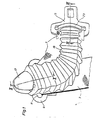
- FIG. 1 shows the area of an upper belt deflection point for a three-point seat belt system in a passenger car with a device for feeding the buckle 5 of this seat belt system.
- a deflection fitting 9 is provided in the upper area of the center pillar of the passenger car, not shown in the drawing.
- the deflection fitting 9 carries one the belt 7 enclosing eyelet 11 and is fastened to the central post by means of a screw 13.
- a shoulder 15 is formed on the must screw 13, which is passed through a covering 17 of the deflection fitting 9 and receives the end of a bellows 19.
- the bellows 19 is used to feed the lock tongue 5 into a convenient position.
- a special feature of the bellows 19 is the fact that it can be brought from a folded rest position into the feed position shown in FIG. 1.
- a double-acting pump is provided (not shown), which either supplies air to the bellows 19 via a line 21 or sucks off air located in the bellows.
- the bellows is therefore made airtight from a soft, elastic material.
- the walls of the bellows 19, which is approximately rectangular in cross section, are of different thicknesses and therefore also of different stiffness.
- the end of the bellows 19 facing the lock tongue 5 is received in a pressure piece 23, against which the lock tongue 5 rests when the bellows 19 is extended.
- the pressure piece 23 also partially encloses the section of the webbing 7 which does not lead to the automatic rewinder of the seat belt system.
- a rivet 25 is attached in the webbing 7 at the appropriate point.
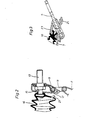
- the device works in such a way that the bellows 19 is initially in a rest position, in which, when folded, it remains near the deflection fitting 9 in a position in which the entry of rear passengers is not hindered.
- a pump is activated via contacts in the seat and on the vehicle door, which inflates the bellows 19 via the line 21. This brings it into its active position.
- the pressure piece 23 slides along the webbing 7 and pushes the lock tongue 5 up to the stop on the rivet 25. In this position, the buckle 5 can be easily gripped by the user and the webbing can thus be pulled out further.
- the pump After inserting and locking the tongue 5 in the associated belt buckle, the pump is switched to suction operation via a corresponding contact, as a result of which vacuum is applied to the inside of the bellows 19 and this retracts into its folded starting position.
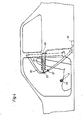
- the bellows denoted therein by 27 is sunk into a recess 29 of the vehicle body in its rest position. If the prerequisites for inflating the falcon bellows 27 are met, the bellows 27 is inflated by a pump 31. As he moves forward, he grips the webbing 35 of the seat belt system with a fork 33 attached to it and guides the user in a straight line into one that is convenient for him Position too. After inserting and latching the buckle 37 held on the webbing 35 with an associated buckle 39, a contact is triggered, which switches the pump 31 to suction operation. As a result, the bellows 27 contracts again and returns to its starting position. This ensures that the seat belt is not in a friction-increasing connection with the device for feeding when the seat belt is fastened.
Landscapes
- Engineering & Computer Science (AREA)
- Mechanical Engineering (AREA)
- Automotive Seat Belt Assembly (AREA)
- Air Bags (AREA)
- Buckles (AREA)
- Devices For Conveying Motion By Means Of Endless Flexible Members (AREA)
- Ropes Or Cables (AREA)
Applications Claiming Priority (2)
| Application Number | Priority Date | Filing Date | Title |
|---|---|---|---|
| DE3343619 | 1983-12-02 | ||
| DE3343619A DE3343619C1 (de) | 1983-12-02 | 1983-12-02 | Vorrichtung zum Zufuehren der Schlosszunge eines Sicherheitsgurtsystems in eine fuerden anzugurtenden Insassen griffguenstige Position |
Publications (3)
| Publication Number | Publication Date |
|---|---|
| EP0149728A2 true EP0149728A2 (fr) | 1985-07-31 |
| EP0149728A3 EP0149728A3 (en) | 1987-09-02 |
| EP0149728B1 EP0149728B1 (fr) | 1990-04-11 |
Family
ID=6215866
Family Applications (1)
| Application Number | Title | Priority Date | Filing Date |
|---|---|---|---|
| EP84112579A Expired - Lifetime EP0149728B1 (fr) | 1983-12-02 | 1984-10-18 | Dispositif pour amener la languette de verrouillage d'une ceinture de sécurité à portée de la main |
Country Status (4)
| Country | Link |
|---|---|
| US (1) | US4600217A (fr) |
| EP (1) | EP0149728B1 (fr) |
| JP (1) | JPS60176848A (fr) |
| DE (2) | DE3343619C1 (fr) |
Cited By (3)
| Publication number | Priority date | Publication date | Assignee | Title |
|---|---|---|---|---|
| WO2007012743A1 (fr) * | 2005-07-29 | 2007-02-01 | Daniel Nonat | Dispositif d'assistance a la prehension de ceinture de securite, et vehicule automobile muni d'un tel dispositif |
| EP1655187A3 (fr) * | 2004-11-05 | 2007-05-02 | Takata Corporation | Dispositif pour retrouver la languette de boucle et système de ceinture de sécurité utilisant celui-ci |
| GB2445148A (en) * | 2006-12-27 | 2008-07-02 | Autoliv Dev | A seat-belt presenter arrangement |
Families Citing this family (27)
| Publication number | Priority date | Publication date | Assignee | Title |
|---|---|---|---|---|
| JPS6248862U (fr) * | 1985-09-17 | 1987-03-26 | ||
| DE3702976C2 (de) * | 1987-02-02 | 1994-03-24 | Linde & Wiemann Gmbh Kg | Dreipunkt-Sicherheitsgurt in einem Kraftfahrzeug |
| US4796915A (en) * | 1987-11-13 | 1989-01-10 | General Motors Corporation | Seat belt extender |
| US4944557A (en) * | 1988-05-27 | 1990-07-31 | Ryozo Tsubai | Seat belt handle assembly |
| JPH02121364U (fr) * | 1989-03-13 | 1990-10-02 | ||
| GB2235361B (en) * | 1989-08-30 | 1993-10-06 | Bsrd Ltd | Seat belt presenter |
| US5058922A (en) * | 1989-10-16 | 1991-10-22 | Long S Craig | Motor vehicle safety belt comfort device |
| US5531470A (en) * | 1992-07-13 | 1996-07-02 | Joalto Design, Inc. | Side air bag incorporated in vehicle outer armrest |
| US5746443A (en) * | 1992-07-13 | 1998-05-05 | Joalto Design, Inc. | Side impact air bag deployable between a vehicle body and an occupant |
| US5378036A (en) * | 1992-07-13 | 1995-01-03 | Townsend; John A. | Sliding automobile door |
| DE4409564A1 (de) * | 1994-03-21 | 1995-06-08 | Daimler Benz Ag | Vorrichtung zur Zuführung der Schloßzunge und des Gurtbandes eines Sicherheitsgurtsystemes in einem Kraftfahrzeug |
| US5476287A (en) * | 1994-11-09 | 1995-12-19 | Lichtwardt; John R. | Method and system for controlling the position of a seat belt relative to an occupant of a vehicle |
| JP3248430B2 (ja) * | 1995-10-05 | 2002-01-21 | トヨタ自動車株式会社 | 車両用シートベルト装置 |
| US6196619B1 (en) | 1995-12-22 | 2001-03-06 | Joalto Design, Inc. | Vehicle closure panel having an intrusion beam as primary structure |
| US5806917A (en) * | 1995-12-22 | 1998-09-15 | Joalto Design, Inc. | Integrated motor vehicle door and chassis |
| US7296825B1 (en) | 1999-05-11 | 2007-11-20 | Autoliv Asp, Inc. | Multiple output buckle switch |
| DE10055845B4 (de) * | 2000-11-10 | 2007-04-12 | Dr.Ing.H.C. F. Porsche Ag | Vorrichtung zur Überführung der Schlosszunge eines Dreipunkt-Sicherheitsgurtes in eine Greifposition |
| US6676162B2 (en) * | 2002-04-24 | 2004-01-13 | Ford Global Technologies, Llc | Occupant restraint belt presenter |
| US20040080203A1 (en) * | 2002-08-05 | 2004-04-29 | Meloul Raphael F | Seatbelt attachment to facilitate seatbelt access |
| FR2860201B1 (fr) * | 2003-09-26 | 2006-12-29 | Peugeot Citroen Automobiles Sa | Dispositif de maintien en attente d'utilisation d'une boucle d'une ceinture de securite. |
| US7011375B1 (en) | 2004-08-30 | 2006-03-14 | Tyler Paul E | Apparatus and method to assist seat belt engagement |
| JP4573296B2 (ja) * | 2004-11-05 | 2010-11-04 | タカタ株式会社 | タング取出しシステムおよびこれを用いたシートベルト装置 |
| DE102005005889B3 (de) * | 2005-02-09 | 2006-08-24 | Isringhausen Gmbh & Co. Kg | Rollenführung für ein Fahrzeugsitz-Schwingsystem mit Scherenführung |
| JP2007030528A (ja) * | 2005-02-16 | 2007-02-08 | Takata Corp | タング取出し補助装置およびこれを用いたシートベルト装置 |
| EP2718156B1 (fr) * | 2011-06-08 | 2016-02-03 | TRW Automotive GmbH | Module comprenant un dispositif de réglage en hauteur de ceinture et un approche-ceinture |
| JP6243218B2 (ja) * | 2013-12-24 | 2017-12-06 | トヨタ自動車株式会社 | シートベルト装置 |
| EP3604029B1 (fr) * | 2015-04-28 | 2021-04-14 | Volvo Car Corporation | Agencement de support avec siège d'enfant |
Family Cites Families (12)
| Publication number | Priority date | Publication date | Assignee | Title |
|---|---|---|---|---|
| US3314719A (en) * | 1965-08-02 | 1967-04-18 | Edsel W Johnson | Erecting seat belt |
| US3300910A (en) * | 1965-12-10 | 1967-01-31 | Isaac Peter | Reelable structural members |
| DE2108483C3 (de) * | 1971-02-23 | 1980-02-14 | Daimler-Benz Ag, 7000 Stuttgart | Sicherheitsgurtsystem in einem Kraftfahrzeug |
| DE2132709C3 (de) * | 1971-07-01 | 1978-08-17 | Ford-Werke Ag, 5000 Koeln | Sicherheitssitz für Kraftfahrzeuge |
| FR2225012A5 (en) * | 1973-04-06 | 1974-10-31 | Hautemont Jean Claude | Automatically unrolling vehicle seat belt - has tube along belt supplied with air from bag in seat compressed by passenger |
| SE7311025L (fr) * | 1973-08-13 | 1975-02-14 | Lindblad O L | |
| DE2713172C2 (de) * | 1977-03-25 | 1986-08-21 | Daimler-Benz Ag, 7000 Stuttgart | Vorrichtung zur Zuführung der Schloßzunge und/oder des Gurtbandes eines Gurtsystemes |
| DE2920094A1 (de) * | 1979-05-18 | 1980-11-27 | Porsche Ag | Betaetigungssystem fuer einen gurtstrang eines sicherheitsgurtes |
| US4360225A (en) * | 1980-04-10 | 1982-11-23 | Allied Corporation | Passive seat belt system |
| DE3120843C2 (de) * | 1981-05-26 | 1986-07-24 | Daimler-Benz Ag, 7000 Stuttgart | Vorrichtung zum Zuführen der Schloßzunge und/oder des Gurtbandes eines Sicherheitsgurtsystems |
| DE3232946A1 (de) * | 1982-09-04 | 1984-03-08 | Wolfgang 5000 Köln Schmalz | Sicherheitsgurt, insbesondere mit automatischer aufrollvorrichtung, mit einem den auflagedruck mindernden polsterteil |
| DE3302356A1 (de) * | 1983-01-25 | 1984-07-26 | Repa Feinstanzwerk Gmbh, 7071 Alfdorf | Zufuehrvorrichtung fuer ein sicherheitsgurtsystem fuer kraftfahrzeuge |
-
1983
- 1983-12-02 DE DE3343619A patent/DE3343619C1/de not_active Expired
-
1984
- 1984-10-18 DE DE8484112579T patent/DE3481904D1/de not_active Expired - Lifetime
- 1984-10-18 EP EP84112579A patent/EP0149728B1/fr not_active Expired - Lifetime
- 1984-11-16 JP JP59243129A patent/JPS60176848A/ja active Pending
- 1984-11-27 US US06/674,590 patent/US4600217A/en not_active Expired - Lifetime
Cited By (5)
| Publication number | Priority date | Publication date | Assignee | Title |
|---|---|---|---|---|
| EP1655187A3 (fr) * | 2004-11-05 | 2007-05-02 | Takata Corporation | Dispositif pour retrouver la languette de boucle et système de ceinture de sécurité utilisant celui-ci |
| WO2007012743A1 (fr) * | 2005-07-29 | 2007-02-01 | Daniel Nonat | Dispositif d'assistance a la prehension de ceinture de securite, et vehicule automobile muni d'un tel dispositif |
| FR2889140A1 (fr) * | 2005-07-29 | 2007-02-02 | Daniel Nonat | Dispositif d'assistance a la prehension de ceinture de securite, et vehicule automobile muni d'un tel dispositif |
| GB2445148A (en) * | 2006-12-27 | 2008-07-02 | Autoliv Dev | A seat-belt presenter arrangement |
| GB2445148B (en) * | 2006-12-27 | 2011-06-08 | Autoliv Dev | A seat-belt presenter arrangement |
Also Published As
| Publication number | Publication date |
|---|---|
| EP0149728B1 (fr) | 1990-04-11 |
| EP0149728A3 (en) | 1987-09-02 |
| DE3343619C1 (de) | 1985-09-05 |
| US4600217A (en) | 1986-07-15 |
| DE3481904D1 (de) | 1990-05-17 |
| JPS60176848A (ja) | 1985-09-10 |
Similar Documents
| Publication | Publication Date | Title |
|---|---|---|
| EP0149728A2 (fr) | Dispositif pour amener la languette de verrouillage d'une ceinture de sécurité à portée de la main | |
| DE3302356A1 (de) | Zufuehrvorrichtung fuer ein sicherheitsgurtsystem fuer kraftfahrzeuge | |
| DE102019216705B4 (de) | Gurtbringer und Fahrzeugsitz mit einem Gurtbringer | |
| DE2400992C2 (de) | Sicherheitsgurtsystem für ein Fahrzeug | |
| WO1999024294B1 (fr) | Systeme de retenue servant a augmenter la securite des passagers d'un vehicule automobile, d'un train ou d'un avion | |
| EP0148747A2 (fr) | Système de ceinture de sécurité | |
| DE102014207036A1 (de) | Verstellvorrichtung für einen Sicherheitsgurt mit einem ausfahrbaren Gurtführungselement | |
| DE4218792A1 (de) | Dreipunktsicherheitsgurtsystem für Kraftfahrzeuge | |
| DE102015204099A1 (de) | Sicherheitsgurteinrichtung für ein Fahrzeug | |
| DE2348532A1 (de) | Auswerfzunge fuer sicherheitsgurtschloss | |
| DE10314464A1 (de) | Gurtbringer für einen Sicherheitsgurt eines Kraftfahrzeuges | |
| EP0802095B1 (fr) | Système de ceinture de sécurité | |
| DE102019208368A1 (de) | Fahrzeugsitz mit einer integrierten Sicherheitsgurteinrichtung und einem Gurtbringer | |
| DE2108483B2 (de) | Sicherheitsgurtsystem in einem Kraftfahrzeug | |
| DE2360702B2 (de) | Sicherheitsgurtanordnung fuer fahrzeuge, insbesondere personenkraftfahrzeuge | |
| DE19720206A1 (de) | Gurtstraffer eines Sicherheitsgurt-Rückhaltesystems | |
| DE4307089C2 (de) | Sicherheitsgurtsystem | |
| DE2643818C2 (de) | Passives Sicherheitsgurtsystem für den Insassen eines Kraftfahrzeuges | |
| EP1270345B1 (fr) | Système de ceinture de sécurité | |
| DE102017104417A1 (de) | Sich automatisch anlegender Dreipunkt-Sicherheitsgurt | |
| DE3514769C2 (fr) | ||
| EP0469326B1 (fr) | Dispositif tendeur pour ceinture de sécurité | |
| WO2004101331A1 (fr) | Systeme de commande pour un systeme de ceintures a 2 points/3 points | |
| DE102014010364B4 (de) | Gurtschloss eines Sicherheitsgurtes eines Fahrzeugs mit einem zwischen einer Ruhestellung und einer Präsentierstellung pneumatisch bewegbaren Schlosskopf | |
| EP0577073A1 (fr) | Procédé pour bloquer le bouton de déverrouillage, respectivement le mécanisme de verrouillage d'une boucle de ceinture de sécurité de véhicule et système de ceinture de sécurité mettant en oeuvre ce procédé |
Legal Events
| Date | Code | Title | Description |
|---|---|---|---|
| PUAI | Public reference made under article 153(3) epc to a published international application that has entered the european phase |
Free format text: ORIGINAL CODE: 0009012 |
|
| 17P | Request for examination filed |
Effective date: 19841018 |
|
| AK | Designated contracting states |
Designated state(s): DE FR GB IT SE |
|
| RAP1 | Party data changed (applicant data changed or rights of an application transferred) |
Owner name: AUDI AG |
|
| PUAL | Search report despatched |
Free format text: ORIGINAL CODE: 0009013 |
|
| AK | Designated contracting states |
Kind code of ref document: A3 Designated state(s): DE FR GB IT SE |
|
| 17Q | First examination report despatched |
Effective date: 19890310 |
|
| ITF | It: translation for a ep patent filed | ||
| GRAA | (expected) grant |
Free format text: ORIGINAL CODE: 0009210 |
|
| AK | Designated contracting states |
Kind code of ref document: B1 Designated state(s): DE FR GB IT SE |
|
| REF | Corresponds to: |
Ref document number: 3481904 Country of ref document: DE Date of ref document: 19900517 |
|
| GBT | Gb: translation of ep patent filed (gb section 77(6)(a)/1977) | ||
| ET | Fr: translation filed | ||
| PLBE | No opposition filed within time limit |
Free format text: ORIGINAL CODE: 0009261 |
|
| STAA | Information on the status of an ep patent application or granted ep patent |
Free format text: STATUS: NO OPPOSITION FILED WITHIN TIME LIMIT |
|
| 26N | No opposition filed | ||
| ITTA | It: last paid annual fee | ||
| EAL | Se: european patent in force in sweden |
Ref document number: 84112579.2 |
|
| PGFP | Annual fee paid to national office [announced via postgrant information from national office to epo] |
Ref country code: GB Payment date: 20010925 Year of fee payment: 18 |
|
| PGFP | Annual fee paid to national office [announced via postgrant information from national office to epo] |
Ref country code: DE Payment date: 20011005 Year of fee payment: 18 |
|
| PGFP | Annual fee paid to national office [announced via postgrant information from national office to epo] |
Ref country code: FR Payment date: 20011018 Year of fee payment: 18 |
|
| PGFP | Annual fee paid to national office [announced via postgrant information from national office to epo] |
Ref country code: SE Payment date: 20011019 Year of fee payment: 18 |
|
| REG | Reference to a national code |
Ref country code: GB Ref legal event code: IF02 |
|
| PG25 | Lapsed in a contracting state [announced via postgrant information from national office to epo] |
Ref country code: GB Free format text: LAPSE BECAUSE OF NON-PAYMENT OF DUE FEES Effective date: 20021018 |
|
| PG25 | Lapsed in a contracting state [announced via postgrant information from national office to epo] |
Ref country code: SE Free format text: LAPSE BECAUSE OF NON-PAYMENT OF DUE FEES Effective date: 20021019 |
|
| PG25 | Lapsed in a contracting state [announced via postgrant information from national office to epo] |
Ref country code: DE Free format text: LAPSE BECAUSE OF NON-PAYMENT OF DUE FEES Effective date: 20030501 |
|
| EUG | Se: european patent has lapsed | ||
| GBPC | Gb: european patent ceased through non-payment of renewal fee |
Effective date: 20021018 |
|
| PG25 | Lapsed in a contracting state [announced via postgrant information from national office to epo] |
Ref country code: FR Free format text: LAPSE BECAUSE OF NON-PAYMENT OF DUE FEES Effective date: 20030630 |
|
| REG | Reference to a national code |
Ref country code: FR Ref legal event code: ST |