EP0149823A2 - Procédé et appareil pour la fabrication de couvercles - Google Patents
Procédé et appareil pour la fabrication de couvercles Download PDFInfo
- Publication number
- EP0149823A2 EP0149823A2 EP84115829A EP84115829A EP0149823A2 EP 0149823 A2 EP0149823 A2 EP 0149823A2 EP 84115829 A EP84115829 A EP 84115829A EP 84115829 A EP84115829 A EP 84115829A EP 0149823 A2 EP0149823 A2 EP 0149823A2
- Authority
- EP
- European Patent Office
- Prior art keywords
- shell
- station
- tooling
- panel
- lip
- Prior art date
- Legal status (The legal status is an assumption and is not a legal conclusion. Google has not performed a legal analysis and makes no representation as to the accuracy of the status listed.)
- Granted
Links
- 238000000034 method Methods 0.000 title claims abstract description 40
- 239000002184 metal Substances 0.000 claims abstract description 11
- 230000015572 biosynthetic process Effects 0.000 claims description 29
- 238000004519 manufacturing process Methods 0.000 claims description 11
- 230000036961 partial effect Effects 0.000 claims description 3
- 238000004826 seaming Methods 0.000 claims description 3
- 238000007493 shaping process Methods 0.000 claims description 2
- 238000007599 discharging Methods 0.000 claims 2
- 239000011257 shell material Substances 0.000 description 171
- 238000012546 transfer Methods 0.000 description 21
- 239000000463 material Substances 0.000 description 15
- 230000037361 pathway Effects 0.000 description 5
- 125000006850 spacer group Chemical group 0.000 description 5
- 238000013022 venting Methods 0.000 description 5
- 230000009471 action Effects 0.000 description 3
- 238000013459 approach Methods 0.000 description 3
- 230000008569 process Effects 0.000 description 3
- 230000002829 reductive effect Effects 0.000 description 3
- 238000002407 reforming Methods 0.000 description 3
- 235000013361 beverage Nutrition 0.000 description 2
- 238000006243 chemical reaction Methods 0.000 description 2
- 230000006835 compression Effects 0.000 description 2
- 238000007906 compression Methods 0.000 description 2
- 230000000694 effects Effects 0.000 description 2
- 238000010008 shearing Methods 0.000 description 2
- 230000002411 adverse Effects 0.000 description 1
- 235000013405 beer Nutrition 0.000 description 1
- 150000001875 compounds Chemical class 0.000 description 1
- 239000000356 contaminant Substances 0.000 description 1
- 230000001276 controlling effect Effects 0.000 description 1
- 230000003247 decreasing effect Effects 0.000 description 1
- 238000010586 diagram Methods 0.000 description 1
- 239000013536 elastomeric material Substances 0.000 description 1
- 235000011389 fruit/vegetable juice Nutrition 0.000 description 1
- 239000007788 liquid Substances 0.000 description 1
- 230000014759 maintenance of location Effects 0.000 description 1
- 238000005259 measurement Methods 0.000 description 1
- 238000004806 packaging method and process Methods 0.000 description 1
- 230000001105 regulatory effect Effects 0.000 description 1
- 230000004044 response Effects 0.000 description 1
- 230000000717 retained effect Effects 0.000 description 1
- 230000002441 reversible effect Effects 0.000 description 1
- 238000005096 rolling process Methods 0.000 description 1
- 238000007789 sealing Methods 0.000 description 1
- 235000014214 soft drink Nutrition 0.000 description 1
- 239000007787 solid Substances 0.000 description 1
- XLYOFNOQVPJJNP-UHFFFAOYSA-N water Substances O XLYOFNOQVPJJNP-UHFFFAOYSA-N 0.000 description 1
Images



Classifications
-
- B—PERFORMING OPERATIONS; TRANSPORTING
- B21—MECHANICAL METAL-WORKING WITHOUT ESSENTIALLY REMOVING MATERIAL; PUNCHING METAL
- B21D—WORKING OR PROCESSING OF SHEET METAL OR METAL TUBES, RODS OR PROFILES WITHOUT ESSENTIALLY REMOVING MATERIAL; PUNCHING METAL
- B21D51/00—Making hollow objects
- B21D51/16—Making hollow objects characterised by the use of the objects
- B21D51/38—Making inlet or outlet arrangements of cans, tins, baths, bottles, or other vessels; Making can ends; Making closures
- B21D51/44—Making closures, e.g. caps
Definitions
- the present invention relates to a method and apparatus for the formation of objects from a flat metallic sheet within a ram press and, more particularly, to such a method and apparatus for the manufacture of shells used to close the ends of metal cans.
- the can body is often manufactured to include the can side walls, and may include an attached bottom end.
- the upper end which includes the means by which the can is opened, is manufactured separately and attached to the can body after the can has been filled.
- the upper can end often referred to within the art as a shell
- typical shells are designed with a flat panel surface surrounded by a countersunk groove from which an almost vertical chuckwall rises.
- a curled lip portion extends outwardly from the upper end of the chuckwall, with the lip portion having a hook-like cross-section.
- shells are manufactured by formation within a ram press.
- This method of formation has in the past resulted in limitations upon the thinness of material used for shells.
- the relative sharp radius of the curves imparted to the shell material to form the countersink results in significant thinning of the material as these curves are formed. This weakens the shell at the very locations where maximum strength is required. Moreover, this can result in splitting of the shell material during formation, after which the shell must be discarded.
- the shell must be formed from stock material of an initial thickness greater than the overall thickness required for proper shell strength.
- a second approach is to provide a double action press which can perform the initial manufacture and subsequent reforming within a single machine. While such a method would decrease the time needed to manufacture a shell, the specialized equipment represents a significant financial burden in replacing presses presently in service. Moreover, curling must still be performed in separate equipment.
- the present invention provides a method and apparatus for forming completed shells for use as can ends.
- a sheet of thin metal is supplied to a first station, at which a generally circular blank is separated from the sheet and partially formed into the shell.
- the partially formed shell is then transferred from the first station along a predetermined path to a second station by striking a blow edgewise of the shell and thereby directing it edgewise rapidly to the second station.
- the partially completed shell is captured and located at the second station, whereupon it is further formed to make the completed shell.
- Tne shell is then discharged from the second station, again by striking a blow edgewise of the shell, propelling the shell toward a discharge station.
- Shell formation as outlined above is performed within a conventional ram press, with the first and second stations each including tooling operated by the press ram. Operations at the first and second stations occur simultaneously, so that as a shell is completed within the second station, the immediately succeeding shell is being initially formed within the first station. The transfer between successive stations is accomplished sufficiently quickly that a shell initially formed within the first station by a first stroke of the press ram will be positioned for final formation within tne second station by the next succeeding stroke.
- the shell formation operation taking place within the first station includes the production of the flat blank from the sheet material by shearing the material between a die cut edge and blank punch, which partially comprise the tooling provided thereat.
- a punch center and die center form ring then cooperate to form a central panel from which rises the chuckwall.
- a lip is also formed extending outward from the upper chuckwall and generally parallel to the panel.
- a relatively large radius of curvature is provided for the junction of the chuckwall with the panel, thereby reducing thinning of the material in this region.
- the forming operation conducted at the second station is carried out with tooling provided thereat.
- a panel form die and panel form punch which partially comprise this tooling, raise the shell panel relative to the chuckwall and lip portion, thereby creating the countersink necessary for shell strength. Additionally, the lip portion is curled to provide the necessary hook for attaching the shell to the can body.
- a single press replaces three separate pieces of machinery (forming press, conversion press, and curling machine) for producing completed can ends.
- the shell may also be coined around the panel periphery within the same press.
- the present invention not only replaces the relatively complex and expensive double-action press with two stations within a single-action press, but also provides for curling, eliminating the need for a separate curling machine.
- the method and apparatus of the present invention enables the shells to be formed with more severe requirements, producing shells of increased concentricity, decreased earring, and reduced stock thickness.
- the shell making method of the present invention may be generally divided into two operations, each of which is carried out within a conventional single-action ram press having a specially adapted tooling and control system.
- the press utilized is a Minster P2-45, although many other models are also suitable for use. Further, each of the two operations could be carried out in separate presses.
- the relatively thin metal stock from which the shell is ultimately formed is fed to one or more stations within the press.
- the press ram operates at each of these first stations to separate a blank from the stock, and to partially form the shell from the blank.
- the partially completed shell formed at each of the first stations is then transferred to a corresponding second station within the same press, whereupon the second portion of the method is begun.
- the press ram is again lowered, the forming of the shells is completed at the second stations.
- the press is opened, the completed shells are transferred out of the press.
- the apparatus is constructed so that for each stroke of the press, a partially formed snell is finished within each second station while a blank is produced and partially formed within each first station. Moreover, the transfer of shells between stations is accomplished so that a shell partially formed in a first station by one press stroke is completed at the second station by the next succeeding stroke.
- the press tooling for each of the first stations 10 is shown generally in Fig. 1.
- the upper tooling 11 is connected for operation by the press ram, while the lower tooling 12 is fixedly mounted to the press frame.
- Lower tooling 12 includes die cut edge 14, over which the metal stock enters the tooling at a level generally indicated by line 16. Die cut edge 14, along with die form ring 18 are solidly supported by block member 20 which is in turn supported by base member 22. Additionally, lower tooling 12 includes draw ring 24, positioned between die form ring 18 and die cut edge 14. A center pressure pad 25 is located concentrically within form ring 18. Draw ring 24 is supported by four springs 26 (only one shown' mounted in base member 22. Springs 26 are shown in Fig. 1 in a compressed condition, caused by pressure exerted upon draw ring 24 when the tooling is closed. The center pressure pad 25 is supported by spring 27 mounted within pressure pad 25 and base member 22 central to the first station tooling. Spring 27 is also shown in a compressed condition from force exerted by the upper tooling 11.
- draw ring 24 and center pressure pad 25 are retained in the lower tooling 12 by flanges 28 and 29 integrally machined on the respective tooling portions with draw ring 24 bottoming against die cut edge 14 and center pressure pad 25 against form ring 18.
- the uppermost surface of draw ring 24 is at a position some distance below the lowest point of shear on the die cut edge 14, while the uppermost surface of the center pressure pad 25 is some distance above draw ring 24 and below lowest point of shear on die cut edge 14.
- Upper tooling 11 is provided with blank punch 30 which is positioned to cooperate with draw ring 24 for compression of spring 26 as the tooling is closed.
- a knockout and positioner 32 is located above die form ring 18, and punch center 34 is provided with an appropriate configuration to produce the partially completed shell, as well as to clamp a blank in cooperation with center pressure pad 25.
- Blank punch 30, knockout and positioner 32, and punch center 34 are all closed simultaneously upon lower tooling 12 as the press ram is lowered.
- Figs. 2-5 The operation of the first station tooling 10 to produce the blank from the stock and partially form a shell is shown in detail in Figs. 2-5.
- Fig. 2 the tooling is shown already partially closed.
- the stock 46 initially entered the tooling along a line indicated at 16, and as the press ram is lowered, a flat blank 48 is produced by shearing the stock material between die cut edge 14 and blank punch 30.
- a spacer ring 49 is provided behind blank punch 30 for setting the lead distance between punch center 34 and blank punch 30.
- the distance by which blank punch 30 leads punch center 34 is less than the distance at which the uppermost surface of center pressure pad 25 is above the uppermost surface of draw ring 24 in lower tooling 12. This allows a blank 48 to be clamped between punch center 34 and center pressure pad 25 first, followed by clamping of blank 48 between blank punch 30 and draw ring 24 before any forming begins. Use of the central clamping secures the blank 48 in a centered position within the tooling during forming of a shell from the blank, as will be described herein.
- the blank punch 30, support ring 32, and punch center 34 all continue to move simultaneously.
- the blank 48 is still pinched between blank punch 30 and draw ring 24, and between punch center 34 and center pressure pad 25, beginning the formation of the shell over die form ring 18. It will be noted that as the blank 48 is formed over form ring 18, it is pulled from between blank punch 30 and draw ring 24.
- the press ram continues to move downward as the punch center 34 begins to form the panel of shell 48 (heretofore referred to as blank 48) .
- the shell material is no longer held between the blank punch 30 and the draw ring 24, but is still contained between punch center 34 and center pad 25, and the draw ring 24 no longer controls the formation of the shell.
- the clearance between the inside diameter of the blank punch 30 and the outside diameter of the die form ring 18 is selected to provide an appropriate amount of drag or resistance on the shell 48 to insure proper formation.
- the inside diameter of blank punch 30 slightly narrows above the curves shown at 49 (shown exaggerated for clarity). Thus, near the end of the press stroke, as can be seen by comparing Figs.
- Fig. 5 the tooling is shown in its closed position with the press ram bottomed against appropriate stop blocks.
- the first portion of the shell formation operation is completed, with a shell 48 being formed having a flat panel 50 terminating at a relatively large radius area 52 to produce a soft stretch so as not to overwork shell material in this area.
- the large radius area 52 forms the junction region of chuckwall 51 with the panel 50, and will later form the shell countersink and panel form radius.
- a sufficiently large radius is provided so that a much tighter radius can later be provided for the shell countersink while maintaining sufficient material thickness. It can be seen from Fig.
- the shell is further provided with a lip 53 extending generally outwardly and upwardly from the chuckwall 51, but having general downward curvature.
- Lip 53 is provided with two distinct curvatures, giving lip 53 a "gull-wing" cross-sectional configuration, with the portion adjacent chuckwall 51 having only slight relative curvature and thus providing the upward extension of lip 53.
- the outermost portion is provided with a relatively sharp downward curvature by die center form ring 18, although the lowermost portion of the outer edge of lip 53 is formed to at least even with, if not above, the point where lip 53 connects with the shell chuckwall 51.
- knockout and positioner 32 does not contact shell 48.
- the press ram is raised to open the tooling.
- shell 48 is held within blank punch 30 by the tight fit of shell 48 therein caused during its formation and is carried upward by upper tooling 11.
- knockout and positioner 32 halts its upward movement of the position relative blank punch 30 and punch center 34 shown in Fig. lb, while blank punch 30 and punch center 34 continue to rise with the press ram toward the uppermost portion of the press stroke shown in Fig. lc.
- shell 48 will contact knockout and positioner 32 which knocks out, or pushes, shell 48 from within the still-moving blank punch 30.
- the shell 48 is then held in position on knockout and positioner 32 through application of a vacuum to shell 48.
- An appropriate fitting 54 is provided for connection to a conventional shop vacuum supply, and passageways 55, 56, 57 and 58 are provided through upper tooling 11 to support the vacuum to the surface of punch center 34. This vacuum then causes the shell 48 to adhere to the surface of knockout and positioner 32.
- the tooling for the second station 60 is shown in detail in Fig. 6.
- Upper tooling 61 connected to the press ram and lower tooling 62 fixedly secured to the press frame are provided, shown in their closed positions.
- Lower tooling 62 includes a curl die 64 and panel form puncn 66, both mounted in turn to base members 68 and 70.
- An insert 71 is mounted within panel form punch 66.
- a spring pressure pad 72 is concentrically mounted between curl die 64 and panel form punch 66, supported by a plurality of springs 74 (only one shown) mounted in member 70 and extending through member 68.
- An appropriate fitting 75 for connection to a vacuum pump is provided, with vacuum passageways 76, 77 and 78 formed through member 68, panel form punch 66 and insert 71, respectively, applying the vacuum to the upper surface of panel form punch 66 insert 71.
- Upper tooling 61 is provided with a retainer 80 connected to upper base 81, mounted in turn to die shoe 82 for movement by the press ram.
- a form punch and positioner 84 is also provided for downward movement along with retainer 80, and includes a projection 85 for defining the forming characteristics of the lower surface of form punch and positioner 84.
- panel form die 86 is mounted generally for movement along with retainer 80 and form punch and positioner 84.
- Panel form die 86 is attached to the lower side of mounting block 88, which is in turn connected to the lower ends of a plurality of springs 90 (only one shown). Springs 90 are secured to the press ram 82. As will be described in detail below, springs 90 are selected to provide a "dwell" in the downward movement of panel form die 86 as the press ram 82 is lowered.
- Vacuum passageways 92, 93, and 94 are provided through panel form die 86, form punch and positioner 84, and mounting block 88, respectively, communicating in turn through an appropriate vacuum fitting 95 and connection thereto to a vacuum pump. Vacuum may be thus supplied to the lower face of panel form die 86.
- FIG. 7-10 The operation of the tooling of each of the second stations 60 for completion of a shell is shown in detail in Figs. 7-10.
- the shell 48 enters the open tooling of the second station 60 from the first station 10, and is properly positioned on lower tooling 62.
- the large radius area 52 and chuckwall 51 are supported by the spring pressure pad 72, with the entire panel 50 some distance above panel form punch insert 71.
- Shell 48 is located and held in place by vacuum applied to shell 48 through passageway 78 within insert 71.
- lowering of the press ram causes panel form die 86 to contact chuckwall 51, clamping it between panel form die 86 and spring pressure pad 72.
- Spring 90 is selected to be more easily compressible than spring 74, so that once contact with chuckwall 51 is made, panel form die 86 is held in position by spring pressure pad 72 and begins to dwell despite further lowering of the press ram. Simultaneously, form punch and positioner 84 contacts shell lip 53.
- Panel form punch insert 71 includes a raised center portion 91, and the raised portion 91 now becomes positioned against the shell panel 50.
- Downward movement of spring pressure pad 72 effectively causes upward movement of the shell panel 50 with respect to the remainder of shell 48, reducing the distance between the uppermost portion of shell 48 and the panel 50.
- the shell material from the large panel radius area 52 of Fig. 7 begins to pull away from the spring pressure pad 72 and wrap around the edges of the panel form punch 66 and the panel form die 86.
- a pressure resistant panel 50 surrounded by countersink 98 and a die curled lip 53 having a hook portion, i. e., an outer curl edge section of relatively lesser radius of curvature, suitable for seaming onto a can are provided.
- the reasons for formation of the "gull-wing" lip 53 at the first station 10 should now be readily appreciatedw
- lip 53 by forming the less sharply curved portion of lip 53 at the first station so as to extend upwardly as well as outwardly from chuckwall 51, some travel distance for lip 53 during die curling of the outermost portion is provided. If lip 53 were to be formed at the first station to extend from chuckwall 51 at the final desired angle, die curling of the outer edge could only be accomplished through transverse movement of some portion of the second station tooling.
- FIG. 10a l An alternative embodiment for the upper tooling 61 is shown in Fig. 10a l wherein the completed shell is coined about the outer edge of panel 50 adjacent countersink 98 for additional strength. While coining of shells is typically performed in a separate coining press, the embodiment of Fig. 10a enables coining to be performed as part of the forming process, eliminating the need for separate equipment and a separate process.
- the central portion of panel form die 86 is provided with an annular recess into which a coining ring 97 and a spacer 99 are placed.
- Coining ring 97 is in turn secured by retainer 101 which is attached to panel form die 86. Spacer 99 is selected so that when the tooling is fully closed as shown in Fig. 10a, the working surface 100 of coining ring 97 contacts the shell 48 and provides sufficient compression to properly coin the outer edge of panel 50 of shell 48.
- a base member 102 extends between a first station 10 and a corresponding second station 60.
- An opening 104 is provided at first station 10, of a diameter sufficient to permit passage therethrough of upper tooling 11 as it is moved downwardly by the press ram into contact with lower tooling 12.
- a second opening 106 of a diameter sufficient to permit passage thereinto of upper tooling 61 in base member 102 is provided at second station 60.
- Lower tooling 62 extends fixedly partially into opening 106, to permit contact with upper tooling 61 as the upper tooling is lowered by the press ram.
- the transfer apparatus includes a driver 110 mounted near each station of the formation apparatus.
- Each driver includes an actuator 112 in the form of an elongated shaft extending from the driver body toward the working surfaces of upper tooling 11 or 61.
- An air valve 114 is associated with each driver 110, adapted to selectively apply compressed air to driver 110. As will be described in detail below, application of compressed air at the appropriate time to driver 110 causes actuator 112 to extend further from the driver housing.
- Valve 114 may be any appropriate relatively quick-acting valve, and is preferably a direct acting solenoid valve such as those manufactured by Schrader Bellows Divison of Scovill Mfg. Co. of Akron, Ohio. The valve 114 is selected so that when the air supply is not connected to driver 110, the driver interior is permitted to exhaust to the atmosphere.
- the sharp blow from driver 110 propels the shell in free flight from the tooling of first station 10. It is important to note that the shell during such flight does not rest on any solid surface, nor is the shell generally directed by any moving parts.
- the shell does move along a defined pathway 116, however, and upper stationary guides 118 are provided to prevent the shell from inadvertently leaving path 116.
- timing of the transfer of the shell from first station 10 to second station 60 is of great importance, since the shell must be properly positioned within second station 60 in time for lowering of the upper tooling 61.
- driver 110 and related items are selected and designed for accurate, quick action. Further, providing a free-flight transfer of the shells ensures that travel time for the shells will not be affected by substantial contact with moving or non-moving parts.
- each shell leave the first station 10 in a precise manner. Since the shell is held against knock-out positioner 32 by vacuum, the vacuum level must be regulated. Too high a vacuum will affect transfer time by slowing the shell as it leaves the upper tooling 11, making shell transfer sluggish.
- Figs. la-lc The preferred approach, shown in Figs. la-lc, is to provide a continuous vacuum bleed to the upper tooling 11 of first station 10. Accordingly, an opening 117 is provided through the wall of knock-out and positioner 32, for cooperation with a slot 119 formed through the wall of blank punch 30. The chamber formed between knock-out and positioner 32 and punch center 34 is therefore vented through opening 117 and slot 119 for all but the uppermost portion of the press stroke (during which portion the shell has already been transferred away), lowering the vacuum applied to the shell to approximately the minimum amount required to retain the shell on knock-out and positioner 32.
- an opening 121 is formed in the wall of knock-out and positioner 32 and an opening 123 is formed in the wall of blank punch 30.
- tnat openings 121 and 123 are aligned at the bottom of the press stroke to cooperate in providing additional venting of the vacuum within upper tooling 11.
- Opening 123 provides an additional venting function at and just beyond the uppermost portion of the press sroke.
- Opening 123 vents the chamber in question during the uppermost portions of the press stroke.
- an additional pathway for the compressed air is provided. This diminishes the air stream from passageway 58 sufficiently to prevent deflection of the shell.
- pairs of each of openings 117, 121, and 123 and slot 119 are provided. It will be recognized, however, that depending upon the particular sizes of the various openings and slots, any desired number of each may be used, provided of course that equal numbers of openings 117 and slots 119 and of openings 121 and 123 are selected.
- Tne driver 110 is shown in detail in Fig. 12, and includes an exterior housing 120. An opening through housing 120 into the interior thereof is provided with an appropriate fitting 122 for connection of driver 110 to its corresponding air valve 114. A piston 124 is disposed within the interior of housing 120 for movement therealong, and is attached to actuator shaft 112 extending through one end of housing 120. Preferably, piston 124 and actuator shaft l12 are integrally formed as a single piece.
- piston 124 As compressed air is delivered to the interior of housing 120 through fitting 122, the resulting air pressure causes movement of piston 124 so as to result in outward extension of actuator 112. Due to the relative light weight of piston 124 relative the pressure of the incoming air, movement of piston 124 occurs sufficiently rapidly to propel a shell away from the tooling. For example, when constructed according to the preferred embodiment, an average velocity is imparted to tne shell typically in the order of 242 in/sec. Shell transfer from first station 10 to second station 60 then occurs in approximately 55 milliseconds. Additionally, the piston 124 need not fit in an airtight relationship within housing 120.
- piston 124 fit only loosely within housing 120, having a piston surface area less than the area of the cross-section of the interior of housing 120. Thus, no seals are required on piston 124, reducing potential sticking and increasing tolerance to contaminants (such as water or oil) carried with the compressed air supply.
- a tip member 126 formed of an elastomeric material is secured to the distal end of actuator 112. Additionally, a spring 127 is placed about actuator 112 between piston 124 and the end of housing 120, to return piston 124 to its original location following closure of valve 114 and discontinuation of the supply of compressed air to driver 110.
- a hole 128 is formed through housing 120 so as to be at least partially open and behind piston 124 when in its actuated position. Hole 128 relieves at least part of the air pressure behind piston 124 once fully moved, thereby facilitating return of piston 124 to its original position.
- a venting slot 129 is defined through housing 120. to vent the interior ahead of as piston 124 as it is moved along the housing interior. By providing venting for air that would otherwise be compressed by piston 124, piston movement is more quickly accomplished, enabling higher press speeds.
- each finger 130 includes an attached lower portion 131 that includes a recessed portion for defining an upper flange 132 and path wall 133 that retain the shell within the pathway along which the shell enters between fingers 130.
- a spring loaded pawl 134 is carried in lower portion 131 and extends slightly into the pathway from each portion 131 to prevent rebounding of the shell as it reaches the end curved surface 135 of the pathway defined by path walls 133.
- the shell is then properly located over lower tooling 62 and, once it has been halted, the shell drops from fingers 130 into lower tooling 62.
- the vacuum supplied to the lower tooling through opening 78 increases the speed with which the shell is moved into its proper position, and facilitates retention of the shell in such position.
- Each finger 130 is pivotally mounted by pins 136 and 137 to blocks 138 and 139, respectively, secured to the base member 102.
- a cam roller 140 is mounted to each finger 130 to cooperate with a plate cam (not shown) mounted to the upper tooling. As the press ram is lowered for the completion of shell formation, the plate cams contact rollers 140, pivoting fingers 130 about pins 136 and 137 to provide proper clearance for the tooling as it closes.
- each finger 130 is provided with a pin 142 to return the fingers to their proper position as the tooling is opened.
- a pin 142 is mounted within each block 139 below pin 137, and includes a projection 143 fittable within an arcuate slot 144 formed within finger 130 as shown in Fig. 14b. Projection 143 cooperates with slot 144 to serve as a stop for finger 130 to properly position the finger for receiving the next shell.
- opening of the tooling at second station 60 causes the completed shell to be lifted upward with upper tooling 61 by the stronger vacuum applied thereto.
- a second driver 110 is energized by valve 114.
- Actuator 112 then strikes the completed shell along its chuck wall, driving the shell from the second station 60 into an appropriate receiving bin or the like. It will be recognized, of course, that transfer of the shell from the second station 60 is substantially identical to that performed from first station 10. Since the shells are merely collected, however, rather than accurately positioned for further operation, the exact path of the shell leaving second station 60 is not as critical as the path for leaving first station 10.
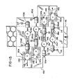
- a press such as that described in the preferred embodiment incorporating the apparatus of the present invention will typically include a plurality of first stations, corresponding second stations, and transfer apparatus. This will enable greater quantities of shells to be formed within a given time, and in one example, apparatus for simultaneous manufacture of four shells is shown in Fig. 15.
- Stock 46 is fed into the press beneath base member 102 supporting the transfer apparatus.
- first stations 10a-10d are provided for severing a blank from the stock 46 and partially forming the shell.
- Each of first stations lOa-lOd includes a corresponding driver 110al-110dl.
- the corresponding driver is actuated to transfer the shell along the transfer path as indicated by arrows 146 to a corresponding section 60a-60d.
- fingers 130 operate to accurately position the shell within the lower tooling of the second station.
- the tooling at each second station 60a-60d closes, thereby completing formation of each shell.
- a corresponding driver 110a2-110d2 is actuated to transfer the completed shells from each of the second stations 60a-60d, as indicated by arrows 148. It should be recognized that at the same time that formation of the shells is completed within the second stations 60a-60d, the next succeeding set of four blanks is punched from the stock 46 and partially formed within the first stations 10a-10d.
- the electrical control means for controlling operation of the press for the manufacture of shells is shown schematically in Fig. 16. Power is supplied to main drive motor 170 through lines Ll, L2 and L3 for driving the press ram to open and close the tooling of the first and second stations.
- a series of operator controls 172 which may be mounted on one or more conveniently located control panels, enable the press operator to control stopping, starting and speed of the press, as well as to control and monitor various other press functions.
- a number of press functions are controlled by a programmable rotary position switch 174 that provides a variety of separate switching functions, each of which may be adjusted to open and close switching contacts at predetermined angular positions.
- Rotary switch 174 is mounted for operation to the press frame, and is coupled to the rotary press ram drive through a drive chain or the like, and hence is coupled indirectly to motor 170 as indicated in Fig. 16.
- the switch is connected to the ram drive so that the switch position designated 0° coincides with the uppermost position of the press ram stroke.
- the electrically operated functions of the press are directed by a microprocessor 176 which interfaces with operator controls 172 and rotary position switch 174.
- the microprocessor 176 is programmed to control various press functions in proper timing and sequence.
- each partially completed and completed shell formed by the press is transferred from a press tooling station by striking the shell with the actuator 112 of a driver 110.
- Driver 110 is in turn actuated by a solenoid-operated air valve 114, two such valves 114 being shown in Fig. 16 for purposes of example.
- the solenoids of valve 114 are energized at the appropriate points in each press stroke by microprocessor 176 in response to signals received from rotary position switch 174.
- micropressor 176 causes each of valves 114 to be energized whenever rotary switch 174 reaches the position of 288°. It should be noted that this position for rotary switch 174 will occur when the press ram has completed most of its upward stroke and the shell has been properly positioned. Each shell will then be struck with the actuator 112 of a driver 110 and will be transferred away from its respective tooling station.
- the total time required for a valve 114 to open and driver 110 to extend actuator 112 is approximately 15 milliseconds. This interval is, of course, constant at all press speeds. Consequently, although each valve l14 is energized at a fixed angular position, the angular position of the rotary switch 174 (and hence the stroke position of the press ram) at the time shell impact actually occurs varies with the speed of the press. For example, at 300 strokes per minute, the rotary switch 174 has reached 315° when the shell is struck.
- microprocessor 176 causes valves 114 to be energized at 273° rather than 288° at press speeds above 300 strokes per minute.
Landscapes
- Engineering & Computer Science (AREA)
- Mechanical Engineering (AREA)
- Shaping Metal By Deep-Drawing, Or The Like (AREA)
- Rigid Containers With Two Or More Constituent Elements (AREA)
Applications Claiming Priority (2)
| Application Number | Priority Date | Filing Date | Title |
|---|---|---|---|
| US06/571,050 US4561280A (en) | 1984-01-16 | 1984-01-16 | Shell making method and apparatus |
| US571050 | 1995-12-12 |
Publications (3)
| Publication Number | Publication Date |
|---|---|
| EP0149823A2 true EP0149823A2 (fr) | 1985-07-31 |
| EP0149823A3 EP0149823A3 (en) | 1985-11-21 |
| EP0149823B1 EP0149823B1 (fr) | 1989-03-29 |
Family
ID=24282126
Family Applications (1)
| Application Number | Title | Priority Date | Filing Date |
|---|---|---|---|
| EP84115829A Expired EP0149823B1 (fr) | 1984-01-16 | 1984-12-19 | Procédé et appareil pour la fabrication de couvercles |
Country Status (10)
| Country | Link |
|---|---|
| US (1) | US4561280A (fr) |
| EP (1) | EP0149823B1 (fr) |
| JP (1) | JPS60158930A (fr) |
| AU (1) | AU566082B2 (fr) |
| CA (1) | CA1246394A (fr) |
| DE (1) | DE3477476D1 (fr) |
| HK (1) | HK63191A (fr) |
| NZ (1) | NZ210586A (fr) |
| SG (1) | SG58691G (fr) |
| ZA (1) | ZA85144B (fr) |
Cited By (6)
| Publication number | Priority date | Publication date | Assignee | Title |
|---|---|---|---|---|
| FR2605911A1 (fr) * | 1986-10-30 | 1988-05-06 | Redicon Corp | Procede et appareil pour former des pieces d'extremite de recipients |
| EP0191271B1 (fr) * | 1984-12-20 | 1990-02-28 | The Stolle Corporation | Estampe séquentielle à porte-outil élastique |
| EP0356975A3 (fr) * | 1988-08-30 | 1991-08-21 | DAYTON RELIABLE TOOL & MFG. CO. | Procédé et appareil pour transférer des objets relativement plats |
| US5527143A (en) * | 1992-10-02 | 1996-06-18 | American National Can Company | Reformed container end |
| US6748789B2 (en) | 2001-10-19 | 2004-06-15 | Rexam Beverage Can Company | Reformed can end for a container and method for producing same |
| US9566634B2 (en) | 2010-06-07 | 2017-02-14 | Rexam Beverage Can Company | Can end produced from downgauged blank |
Families Citing this family (18)
| Publication number | Priority date | Publication date | Assignee | Title |
|---|---|---|---|---|
| US4862722A (en) * | 1984-01-16 | 1989-09-05 | Dayton Reliable Tool & Mfg. Co. | Method for forming a shell for a can type container |
| US4704887A (en) * | 1984-01-16 | 1987-11-10 | Dayton Reliable Tool & Mfg. Co. | Method and apparatus for making shells for can ends |
| US4696179A (en) * | 1986-02-06 | 1987-09-29 | Dayton Reliable Tool & Mfg. Co. | Air assist means for use in transferring relatively flat objects |
| US4770022A (en) * | 1987-02-27 | 1988-09-13 | Dayton Reliable Tool & Mfg. Co. | Method and apparatus for transferring relatively flat objects |
| US5209098A (en) * | 1987-10-05 | 1993-05-11 | Reynolds Metals Company | Method and apparatus for forming can ends |
| US5331836A (en) * | 1987-10-05 | 1994-07-26 | Reynolds Metals Company | Method and apparatus for forming can ends |
| US4977772A (en) * | 1988-09-02 | 1990-12-18 | Redicon Corporation | Method and apparatus for forming reforming and curling shells in a single press |
| US4903521A (en) * | 1988-09-02 | 1990-02-27 | Redicon Corporation | Method and apparatus for forming, reforming and curling shells in a single press |
| JPH0677783B2 (ja) * | 1988-09-05 | 1994-10-05 | 東洋製罐株式会社 | 金属蓋およびその製造方法 |
| US5044189A (en) * | 1990-01-19 | 1991-09-03 | Dayton Reliable Tool & Mfg. Co. | Scrap guiding and chopping in a shell press |
| US5287718A (en) * | 1991-01-16 | 1994-02-22 | Toyo Saikan Kaisha, Ltd. | Curl forming method for a can end |
| US5349843A (en) * | 1992-08-06 | 1994-09-27 | Buhrke Industries, Inc. | Overhead belt discharge apparatus for container end closures |
| US6024239A (en) * | 1997-07-03 | 2000-02-15 | American National Can Company | End closure with improved openability |
| US6349584B1 (en) | 2000-05-17 | 2002-02-26 | Precision Machining Services, Inc. | Apparatus for curling shells for beverage containers |
| US20020113069A1 (en) * | 2000-12-27 | 2002-08-22 | Forrest Randy G. | Can end for a container |
| EP2851140B1 (fr) * | 2013-09-20 | 2016-05-18 | Crown Packaging Technology Inc | Production d'extrémité de canette |
| US20180044155A1 (en) | 2016-08-12 | 2018-02-15 | Ball Corporation | Apparatus and Methods of Capping Metallic Bottles |
| MX2020002563A (es) * | 2017-09-15 | 2020-07-13 | Ball Corp | Sistema y metodo de formar una tapa metalica para un contenedor roscado. |
Family Cites Families (10)
| Publication number | Priority date | Publication date | Assignee | Title |
|---|---|---|---|---|
| US3537291A (en) * | 1967-10-04 | 1970-11-03 | Reynolds Metals Co | Apparatus for and method of forming an end closure for a can |
| US3866471A (en) * | 1973-12-03 | 1975-02-18 | Kaller Die & Tool Company | Progressive die |
| US3957005A (en) * | 1974-06-03 | 1976-05-18 | Aluminum Company Of America | Method for making a metal can end |
| US3952677A (en) * | 1974-06-27 | 1976-04-27 | American Can Company | Curled container bodies, method of securing closures thereto and containers formed thereby |
| US4157693A (en) * | 1977-11-10 | 1979-06-12 | National Can Corporation | Seamless drawn and ironed container with opening means and method and apparatus for forming the same |
| US4291567A (en) * | 1978-03-03 | 1981-09-29 | Japan Crown Cork Co., Ltd. | Easily openable container closure having a shell and a sealing member, apparatus for producing the same |
| US4448322A (en) * | 1978-12-08 | 1984-05-15 | National Can Corporation | Metal container end |
| US4215795A (en) * | 1979-02-02 | 1980-08-05 | Owens-Illinois, Inc. | End structure for a can body and method of making same |
| US4372720A (en) * | 1980-09-04 | 1983-02-08 | American Can Company | Forming of end closures |
| US4382737A (en) * | 1981-03-05 | 1983-05-10 | Gulf & Western Manufacturing Company | Can end making apparatus |
-
1984
- 1984-01-16 US US06/571,050 patent/US4561280A/en not_active Expired - Fee Related
- 1984-12-17 NZ NZ210586A patent/NZ210586A/en unknown
- 1984-12-19 EP EP84115829A patent/EP0149823B1/fr not_active Expired
- 1984-12-19 DE DE8484115829T patent/DE3477476D1/de not_active Expired
-
1985
- 1985-01-07 ZA ZA85144A patent/ZA85144B/xx unknown
- 1985-01-07 CA CA000471596A patent/CA1246394A/fr not_active Expired
- 1985-01-08 AU AU37512/85A patent/AU566082B2/en not_active Ceased
- 1985-01-16 JP JP60005595A patent/JPS60158930A/ja active Granted
-
1991
- 1991-07-22 SG SG586/91A patent/SG58691G/en unknown
- 1991-08-15 HK HK631/91A patent/HK63191A/en unknown
Cited By (8)
| Publication number | Priority date | Publication date | Assignee | Title |
|---|---|---|---|---|
| EP0191271B1 (fr) * | 1984-12-20 | 1990-02-28 | The Stolle Corporation | Estampe séquentielle à porte-outil élastique |
| FR2605911A1 (fr) * | 1986-10-30 | 1988-05-06 | Redicon Corp | Procede et appareil pour former des pieces d'extremite de recipients |
| EP0356975A3 (fr) * | 1988-08-30 | 1991-08-21 | DAYTON RELIABLE TOOL & MFG. CO. | Procédé et appareil pour transférer des objets relativement plats |
| US5527143A (en) * | 1992-10-02 | 1996-06-18 | American National Can Company | Reformed container end |
| US6748789B2 (en) | 2001-10-19 | 2004-06-15 | Rexam Beverage Can Company | Reformed can end for a container and method for producing same |
| US7748563B2 (en) | 2001-10-19 | 2010-07-06 | Rexam Beverage Can Company | Reformed can end for a container and method for producing same |
| US9566634B2 (en) | 2010-06-07 | 2017-02-14 | Rexam Beverage Can Company | Can end produced from downgauged blank |
| US10486852B2 (en) | 2010-06-07 | 2019-11-26 | Rexam Beverage Can Company | Can end produced from downgauged blank |
Also Published As
| Publication number | Publication date |
|---|---|
| SG58691G (en) | 1991-08-23 |
| JPH0521659B2 (fr) | 1993-03-25 |
| JPS60158930A (ja) | 1985-08-20 |
| US4561280A (en) | 1985-12-31 |
| EP0149823B1 (fr) | 1989-03-29 |
| AU3751285A (en) | 1985-07-25 |
| HK63191A (en) | 1991-08-23 |
| NZ210586A (en) | 1986-11-12 |
| DE3477476D1 (en) | 1989-05-03 |
| ZA85144B (en) | 1985-08-28 |
| AU566082B2 (en) | 1987-10-08 |
| EP0149823A3 (en) | 1985-11-21 |
| CA1246394A (fr) | 1988-12-13 |
Similar Documents
| Publication | Publication Date | Title |
|---|---|---|
| US4561280A (en) | Shell making method and apparatus | |
| EP0149185B1 (fr) | Procédé et appareil pour fabriquer des couvercles de boîtes | |
| US4735863A (en) | Shell for can | |
| JPH0424129B2 (fr) | ||
| US3435653A (en) | Forming method and apparatus | |
| US4862722A (en) | Method for forming a shell for a can type container | |
| EP0151298B1 (fr) | Couvercle de boîte | |
| US4599884A (en) | Apparatus for transferring relatively flat objects | |
| US4895012A (en) | Method and apparatus for transferring relatively flat objects | |
| JPH07508934A (ja) | 引き抜き製品をパンチから抜き取る装置 | |
| CA1277549C (fr) | Methode et dispositif de transfert d'objets relativement plans | |
| US4637961A (en) | Shell for can ends | |
| GB2056327A (en) | Making cup-shaped cylindrical shells | |
| NZ218733A (en) | Apparatus for catching articles hit by "kicker" member | |
| US3039413A (en) | Can fabricating mechanism | |
| EP1036607A2 (fr) | Procede et dispositif pour former une coupelle avec un fond profile | |
| JP3771349B2 (ja) | 異形底カップを形成するための方法及び装置 |
Legal Events
| Date | Code | Title | Description |
|---|---|---|---|
| PUAI | Public reference made under article 153(3) epc to a published international application that has entered the european phase |
Free format text: ORIGINAL CODE: 0009012 |
|
| AK | Designated contracting states |
Designated state(s): BE CH DE FR GB IT LI NL SE |
|
| PUAL | Search report despatched |
Free format text: ORIGINAL CODE: 0009013 |
|
| AK | Designated contracting states |
Designated state(s): BE CH DE FR GB IT LI NL SE |
|
| 17P | Request for examination filed |
Effective date: 19860507 |
|
| 17Q | First examination report despatched |
Effective date: 19861022 |
|
| GRAA | (expected) grant |
Free format text: ORIGINAL CODE: 0009210 |
|
| AK | Designated contracting states |
Kind code of ref document: B1 Designated state(s): BE CH DE FR GB IT LI NL SE |
|
| REF | Corresponds to: |
Ref document number: 3477476 Country of ref document: DE Date of ref document: 19890503 |
|
| ITF | It: translation for a ep patent filed | ||
| ET | Fr: translation filed | ||
| PLBE | No opposition filed within time limit |
Free format text: ORIGINAL CODE: 0009261 |
|
| STAA | Information on the status of an ep patent application or granted ep patent |
Free format text: STATUS: NO OPPOSITION FILED WITHIN TIME LIMIT |
|
| 26N | No opposition filed | ||
| ITTA | It: last paid annual fee | ||
| EAL | Se: european patent in force in sweden |
Ref document number: 84115829.8 |
|
| PGFP | Annual fee paid to national office [announced via postgrant information from national office to epo] |
Ref country code: GB Payment date: 19951211 Year of fee payment: 12 |
|
| PGFP | Annual fee paid to national office [announced via postgrant information from national office to epo] |
Ref country code: FR Payment date: 19951212 Year of fee payment: 12 |
|
| PGFP | Annual fee paid to national office [announced via postgrant information from national office to epo] |
Ref country code: SE Payment date: 19951215 Year of fee payment: 12 |
|
| PGFP | Annual fee paid to national office [announced via postgrant information from national office to epo] |
Ref country code: DE Payment date: 19951222 Year of fee payment: 12 |
|
| PGFP | Annual fee paid to national office [announced via postgrant information from national office to epo] |
Ref country code: NL Payment date: 19951230 Year of fee payment: 12 |
|
| PGFP | Annual fee paid to national office [announced via postgrant information from national office to epo] |
Ref country code: CH Payment date: 19960125 Year of fee payment: 12 |
|
| PGFP | Annual fee paid to national office [announced via postgrant information from national office to epo] |
Ref country code: BE Payment date: 19960130 Year of fee payment: 12 |
|
| PG25 | Lapsed in a contracting state [announced via postgrant information from national office to epo] |
Ref country code: GB Effective date: 19961219 |
|
| PG25 | Lapsed in a contracting state [announced via postgrant information from national office to epo] |
Ref country code: SE Effective date: 19961220 |
|
| PG25 | Lapsed in a contracting state [announced via postgrant information from national office to epo] |
Ref country code: LI Effective date: 19961231 Ref country code: CH Effective date: 19961231 Ref country code: BE Effective date: 19961231 |
|
| BERE | Be: lapsed |
Owner name: DAYTON RELIABLE TOOL & MFG CO. Effective date: 19961231 |
|
| PG25 | Lapsed in a contracting state [announced via postgrant information from national office to epo] |
Ref country code: NL Effective date: 19970701 |
|
| GBPC | Gb: european patent ceased through non-payment of renewal fee |
Effective date: 19961219 |
|
| REG | Reference to a national code |
Ref country code: CH Ref legal event code: PL |
|
| PG25 | Lapsed in a contracting state [announced via postgrant information from national office to epo] |
Ref country code: FR Effective date: 19970829 |
|
| NLV4 | Nl: lapsed or anulled due to non-payment of the annual fee |
Effective date: 19970701 |
|
| PG25 | Lapsed in a contracting state [announced via postgrant information from national office to epo] |
Ref country code: DE Effective date: 19970902 |
|
| EUG | Se: european patent has lapsed |
Ref document number: 84115829.8 |
|
| REG | Reference to a national code |
Ref country code: FR Ref legal event code: ST |