EP0149831A2 - Procédé d'économie d'énergie dans des colonnes de distillation - Google Patents
Procédé d'économie d'énergie dans des colonnes de distillation Download PDFInfo
- Publication number
- EP0149831A2 EP0149831A2 EP84115888A EP84115888A EP0149831A2 EP 0149831 A2 EP0149831 A2 EP 0149831A2 EP 84115888 A EP84115888 A EP 84115888A EP 84115888 A EP84115888 A EP 84115888A EP 0149831 A2 EP0149831 A2 EP 0149831A2
- Authority
- EP
- European Patent Office
- Prior art keywords
- distillation
- determined
- rising
- liquid
- temperature
- Prior art date
- Legal status (The legal status is an assumption and is not a legal conclusion. Google has not performed a legal analysis and makes no representation as to the accuracy of the status listed.)
- Withdrawn
Links
- 238000004821 distillation Methods 0.000 title claims abstract description 38
- 238000000034 method Methods 0.000 title claims description 18
- 239000007788 liquid Substances 0.000 claims description 30
- 230000000630 rising effect Effects 0.000 claims description 17
- 230000004087 circulation Effects 0.000 claims description 6
- 238000004088 simulation Methods 0.000 claims description 4
- 238000011084 recovery Methods 0.000 abstract description 2
- 239000004215 Carbon black (E152) Substances 0.000 description 9
- 229930195733 hydrocarbon Natural products 0.000 description 9
- 150000002430 hydrocarbons Chemical class 0.000 description 9
- 238000012545 processing Methods 0.000 description 9
- 239000010779 crude oil Substances 0.000 description 8
- XLYOFNOQVPJJNP-UHFFFAOYSA-N water Substances O XLYOFNOQVPJJNP-UHFFFAOYSA-N 0.000 description 7
- 239000003517 fume Substances 0.000 description 6
- 239000007789 gas Substances 0.000 description 6
- 239000000047 product Substances 0.000 description 4
- 239000000463 material Substances 0.000 description 3
- 238000004364 calculation method Methods 0.000 description 2
- 238000005516 engineering process Methods 0.000 description 2
- 238000012546 transfer Methods 0.000 description 2
- 238000013459 approach Methods 0.000 description 1
- 238000009835 boiling Methods 0.000 description 1
- 238000012512 characterization method Methods 0.000 description 1
- 238000009833 condensation Methods 0.000 description 1
- 230000005494 condensation Effects 0.000 description 1
- 230000000694 effects Effects 0.000 description 1
- 238000011156 evaluation Methods 0.000 description 1
- 238000002474 experimental method Methods 0.000 description 1
- 239000012263 liquid product Substances 0.000 description 1
- 238000005259 measurement Methods 0.000 description 1
- 239000000203 mixture Substances 0.000 description 1
- 238000010992 reflux Methods 0.000 description 1
Images

Classifications
-
- B—PERFORMING OPERATIONS; TRANSPORTING
- B01—PHYSICAL OR CHEMICAL PROCESSES OR APPARATUS IN GENERAL
- B01D—SEPARATION
- B01D3/00—Distillation or related exchange processes in which liquids are contacted with gaseous media, e.g. stripping
- B01D3/007—Energy recuperation; Heat pumps
-
- Y—GENERAL TAGGING OF NEW TECHNOLOGICAL DEVELOPMENTS; GENERAL TAGGING OF CROSS-SECTIONAL TECHNOLOGIES SPANNING OVER SEVERAL SECTIONS OF THE IPC; TECHNICAL SUBJECTS COVERED BY FORMER USPC CROSS-REFERENCE ART COLLECTIONS [XRACs] AND DIGESTS
- Y02—TECHNOLOGIES OR APPLICATIONS FOR MITIGATION OR ADAPTATION AGAINST CLIMATE CHANGE
- Y02P—CLIMATE CHANGE MITIGATION TECHNOLOGIES IN THE PRODUCTION OR PROCESSING OF GOODS
- Y02P70/00—Climate change mitigation technologies in the production process for final industrial or consumer products
- Y02P70/10—Greenhouse gas [GHG] capture, material saving, heat recovery or other energy efficient measures, e.g. motor control, characterised by manufacturing processes, e.g. for rolling metal or metal working
Definitions
- the invention relates to a method for determining the heat recovery potential of distillation columns from experimentally easily measurable data, while reducing the heat consumption of the distillation.
- the described prior art has in common that certain data relating to the energy and material flows in the distillation columns are selected, with different evaluations of the data to be selected. The selected measurement data are then evaluated in computer systems and used to control the mode of operation of the distillation column.
- the sizes m i , m head gas and m process water are easy to measure, but not the sizes V and L.
- Equation 2 A second equation is used to determine V and L: h in this equation means the respective specific enthalpy.
- V and L can be calculated on the respective floor.
- the stripped amount of steam d is determined by balancing the mass and energy flows around the side stripper.
- the problem with this approach is that the density of the amount of steam stripped is unknown and must be estimated, as the authors concede.
- the density of heat circuits is to be estimated by interpolation of the densities determined using the above method.
- their enthalpies are not determined directly from their material data, but from the material data of the products and the outflowing liquids L for the respective temperature of the steam by means of a mixture calculation.
- the present invention has now achieved this object in a manner which is surprising and unpredictable for the person skilled in the art, by a method for saving energy in distillation columns by determining the amounts of steam rising through the still plates and the amounts of liquid flowing down through the still plates, in particular on the discharge trays of the distillation columns , With the knowledge of these quantities the energy supply to the distillation column is minimized in a manner known per se, characterized in that the density of the liquid drawn off laterally on a distillation tray is determined and from this with the aid of functions, in particular those determined by simulation programs, the densities of the a bottom of the still flowing liquid and upward rising vapors are determined, and that the temperature of the bottom of the distillation is determined and from this with the help of, in particular by S functions, the temperature of the vapors rising in this still bottom is determined.
- both the density of the liquid flowing down from a floor and the density of the vapor rising on this floor can be determined.
- the present invention surprisingly shows for the person skilled in the art that the densities of the liquid obtained from the liquid are drawn off in an unpredictably simple manner Allow liquid and the vapor rising through the floor to determine the floor drain and fumes precisely and easily. Likewise, the temperature of the rising steam in a floor can be determined precisely and easily by measuring the temperature of this floor or the liquid thereon.
- the technical teaching of the present invention therefore involves the saving of energy in distillation columns by measuring the densities of the liquids drawn off laterally on the trays (on the discharge trays) and by measuring the temperature of the liquid flowing downward on such trays and certain relationships to the densities the liquids and vapors and their temperatures inside the column.
- the present invention applies to all distillation columns, but is of particular importance for crude oil columns (crude oil distillation at normal pressure) which are equipped with lateral circulations and side strippers, the circulations known to serve to transfer heat to the crude oil used in the heat exchange.
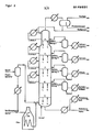
- FIGS. 1 and 2 serve for further explanation.
- FIG. 1 represents the uppermost discharge tray of a distillation column.
- FIG. 2 represents a typical crude oil column.
- liquid product is withdrawn from the top side extractor on the right; the overhead fraction, which contains process water, is passed overhead.
- the overhead fraction which contains process water, is passed overhead.
- top gas and water are separated from each other, as well as raw gasoline that has gone overhead.
- a so-called heavy naphtha fraction is drawn off on the right-hand side under the distillation tray and flows through a stripper.
- the side circulation is designed in a manner not explained in more detail as a heat exchanger for crude oil used.
- the distillation tray shown in Figure 1 the quantity of liquid L flows downwards, while the quantity of vapor V flows upwards through the bottom.
- FIG. 2 shows a typical crude oil distillation column which has 4 side draws and, at the level of these side draws, 4 circulations for heat exchange.
- the heat exchangers are used in an unspecified manner for heat transfer to feed products.
- the furnace at the bottom left is used to heat up the crude oil.
- the flash container on the left is used to drive off low-boiling components in the crude oil.
- equations determined according to the invention can also have the following or different forms:
- the densities and temperatures of the vapors and liquids on the trays change with the amount of the rising vapors or with the reflux and thus with the energy supply to the column.
- the mass flows mentioned can be determined from the easily determined standard densities of the liquid drawn off and the easy to determine temperatures of the liquids on the floors and according to the relationships according to the invention.
- the overflash amount is determined from the density of the distillation residue taken off or the temperature in the flash zone.
- the process according to the invention can also be used with any other distillation columns, provided the standard densities of the distillation products are known.
Landscapes
- Chemical & Material Sciences (AREA)
- Chemical Kinetics & Catalysis (AREA)
- Production Of Liquid Hydrocarbon Mixture For Refining Petroleum (AREA)
- Vaporization, Distillation, Condensation, Sublimation, And Cold Traps (AREA)
Applications Claiming Priority (2)
| Application Number | Priority Date | Filing Date | Title |
|---|---|---|---|
| DE19843401830 DE3401830A1 (de) | 1984-01-20 | 1984-01-20 | Verfahren zur energieeinsparung in destillationskolonnen |
| DE3401830 | 1984-01-20 |
Publications (1)
| Publication Number | Publication Date |
|---|---|
| EP0149831A2 true EP0149831A2 (fr) | 1985-07-31 |
Family
ID=6225408
Family Applications (1)
| Application Number | Title | Priority Date | Filing Date |
|---|---|---|---|
| EP84115888A Withdrawn EP0149831A2 (fr) | 1984-01-20 | 1984-12-20 | Procédé d'économie d'énergie dans des colonnes de distillation |
Country Status (2)
| Country | Link |
|---|---|
| EP (1) | EP0149831A2 (fr) |
| DE (1) | DE3401830A1 (fr) |
Cited By (2)
| Publication number | Priority date | Publication date | Assignee | Title |
|---|---|---|---|---|
| US6333725B1 (en) | 1998-06-30 | 2001-12-25 | Daewoo Electronics, Co., Ltd. | Data interfacing apparatus of AC type plasma display panel system |
| US7208570B2 (en) | 2004-02-18 | 2007-04-24 | Forchem Oy | Method of refining tall oil |
-
1984
- 1984-01-20 DE DE19843401830 patent/DE3401830A1/de not_active Withdrawn
- 1984-12-20 EP EP84115888A patent/EP0149831A2/fr not_active Withdrawn
Cited By (2)
| Publication number | Priority date | Publication date | Assignee | Title |
|---|---|---|---|---|
| US6333725B1 (en) | 1998-06-30 | 2001-12-25 | Daewoo Electronics, Co., Ltd. | Data interfacing apparatus of AC type plasma display panel system |
| US7208570B2 (en) | 2004-02-18 | 2007-04-24 | Forchem Oy | Method of refining tall oil |
Also Published As
| Publication number | Publication date |
|---|---|
| DE3401830A1 (de) | 1985-07-25 |
Similar Documents
| Publication | Publication Date | Title |
|---|---|---|
| DE69926279T2 (de) | Verfahren und Vorrichtung zur Destillation | |
| EP1040857B1 (fr) | Procédé de séparation par distillation continu d'une substance fondant à haute température | |
| EP0126288A2 (fr) | Procédé d'opération de réactions chimiques et séparation simultanée par distillation d'un mélange en plusieurs fractions au moyen d'une colonne de distillation | |
| DE3522234C2 (de) | Verfahren zum energiegünstigen Betreiben einer Destillationskolonne | |
| EP0046876A1 (fr) | Procédé de traitement du produit de fond de procédés de distillation extractive pour l'obtention d'hydrocarbures purs | |
| DE10019196C1 (de) | Verfahren zur Gewinnung eines aus Benzol und Toluol oder Toluol und Xylol bestehenden Aromatenproduktes hoher Reinheit aus einem Nichtaromaten enthaltenden eng- oder azeotropsiedenden Vorprodukt und Anlage zur Durchführung des Verfahrens | |
| EP0380001A1 (fr) | Procédé de séparation destillative de quantité minime d'une fraction d'éballonnement moyenne d'une mélange de liquide | |
| EP0460037B1 (fr) | Systeme de diagnostic et de regulation de colonnes de rectification a l'aide d'un modele | |
| DE824786C (de) | Verfahren und Vorrichtung zur selektiven Absorption und Abscheidung von Daempfen undGasen | |
| DE3401830A1 (de) | Verfahren zur energieeinsparung in destillationskolonnen | |
| DE3338488C2 (fr) | ||
| DE10144239A1 (de) | Verfahren zur Prozeßführung einer Extraktivdestillationsanlage, Prozeßleitsystem und Extraktivdestillationsanlage | |
| DE2916175C2 (fr) | ||
| DE807812C (de) | Verfahren und Vorrichtung zum Destillieren und Kondensieren | |
| EP0638345B1 (fr) | Procédé d'exécution de séparation par distillation pour des modes de fonctionnement discontinus | |
| DE3901587A1 (de) | Verfahren zur aufarbeitung des raffinates einer extraktivdestillation von kohlenwasserstoffgemischen | |
| EP0505723B1 (fr) | Procédé pour la séparation des arômatiques par distillation extractive | |
| DE1767836A1 (de) | Dekantiervorrichtung | |
| DE1543104C3 (de) | Verfahren zur Abtrennung reiner Aromaten aus Gemischen von Aromaten mit Nichtaromaten mit Hilfe der Extraktivdestillation | |
| DE4205885C1 (en) | System for sepg. oil slops or emulsions into water, petrol, oil and solids - in which slop oil is heated in circuit comprising heater, column and pump and slop oil from bottom of column is cooled and sepd. into clean oil phase and solid phase | |
| DE1803991B2 (de) | Vorrichtung zur selbsttätigen Regelung einer Fraktionierkolonne mit Seitenproduktabnahme | |
| DE3209425C2 (fr) | ||
| DE903260C (de) | Verfahren zur Gewinnung von reinem Propan und reinem Butan durch kontinuierliche Destillation von C, C, C-Kohlenwasserstoffen und deren Gemischen | |
| AT160881B (de) | Verfahren zur Regelung von dauernd arbeitenden Fraktionierdestillationsapparaten | |
| DE3537139A1 (de) | Anlage zur kontinuierlichen fettspaltung |
Legal Events
| Date | Code | Title | Description |
|---|---|---|---|
| PUAI | Public reference made under article 153(3) epc to a published international application that has entered the european phase |
Free format text: ORIGINAL CODE: 0009012 |
|
| 17P | Request for examination filed |
Effective date: 19841220 |
|
| AK | Designated contracting states |
Designated state(s): BE DE FR GB IT NL |
|
| ITCL | It: translation for ep claims filed |
Representative=s name: SOCIETA' ITALIANA BREVETTI S.P.A. |
|
| EL | Fr: translation of claims filed | ||
| TCNL | Nl: translation of patent claims filed | ||
| STAA | Information on the status of an ep patent application or granted ep patent |
Free format text: STATUS: THE APPLICATION HAS BEEN WITHDRAWN |
|
| 18W | Application withdrawn |
Withdrawal date: 19870211 |
|
| RIN1 | Information on inventor provided before grant (corrected) |
Inventor name: LUEHRS, ARMIN, DIPL.-ING. |