EP0149848B1 - Verfahren und Anlage zum Heissregenerieren und Wiederverwenden an Ort und Stelle von alten Strassendecken - Google Patents
Verfahren und Anlage zum Heissregenerieren und Wiederverwenden an Ort und Stelle von alten Strassendecken Download PDFInfo
- Publication number
- EP0149848B1 EP0149848B1 EP84116386A EP84116386A EP0149848B1 EP 0149848 B1 EP0149848 B1 EP 0149848B1 EP 84116386 A EP84116386 A EP 84116386A EP 84116386 A EP84116386 A EP 84116386A EP 0149848 B1 EP0149848 B1 EP 0149848B1
- Authority
- EP
- European Patent Office
- Prior art keywords
- plant
- panels
- mixers
- heating
- scarifying
- Prior art date
- Legal status (The legal status is an assumption and is not a legal conclusion. Google has not performed a legal analysis and makes no representation as to the accuracy of the status listed.)
- Expired - Lifetime
Links
- 238000000034 method Methods 0.000 title claims abstract description 35
- 238000004064 recycling Methods 0.000 title claims abstract description 10
- 238000011065 in-situ storage Methods 0.000 title claims abstract description 8
- 230000008929 regeneration Effects 0.000 title claims abstract description 5
- 238000011069 regeneration method Methods 0.000 title claims abstract description 5
- 239000000463 material Substances 0.000 claims abstract description 60
- 238000010438 heat treatment Methods 0.000 claims abstract description 34
- 239000002344 surface layer Substances 0.000 claims abstract description 7
- 238000005096 rolling process Methods 0.000 claims abstract description 4
- 238000000576 coating method Methods 0.000 claims description 29
- 239000011248 coating agent Substances 0.000 claims description 28
- 238000002156 mixing Methods 0.000 claims description 18
- 238000007788 roughening Methods 0.000 claims description 4
- 239000010410 layer Substances 0.000 description 15
- 206010039509 Scab Diseases 0.000 description 5
- 230000007547 defect Effects 0.000 description 4
- 239000010426 asphalt Substances 0.000 description 3
- 230000010354 integration Effects 0.000 description 3
- ATUOYWHBWRKTHZ-UHFFFAOYSA-N Propane Chemical compound CCC ATUOYWHBWRKTHZ-UHFFFAOYSA-N 0.000 description 2
- 239000003795 chemical substances by application Substances 0.000 description 2
- 238000012423 maintenance Methods 0.000 description 2
- 238000003801 milling Methods 0.000 description 2
- 230000035515 penetration Effects 0.000 description 2
- 238000011084 recovery Methods 0.000 description 2
- 239000011230 binding agent Substances 0.000 description 1
- 238000001816 cooling Methods 0.000 description 1
- 230000001054 cortical effect Effects 0.000 description 1
- 230000006866 deterioration Effects 0.000 description 1
- 238000009826 distribution Methods 0.000 description 1
- 230000000694 effects Effects 0.000 description 1
- 238000004880 explosion Methods 0.000 description 1
- 238000010304 firing Methods 0.000 description 1
- 239000000446 fuel Substances 0.000 description 1
- 230000009931 harmful effect Effects 0.000 description 1
- 239000011810 insulating material Substances 0.000 description 1
- 239000001294 propane Substances 0.000 description 1
- 238000004904 shortening Methods 0.000 description 1
- 239000007921 spray Substances 0.000 description 1
- 238000005507 spraying Methods 0.000 description 1
- 239000002345 surface coating layer Substances 0.000 description 1
- 238000009966 trimming Methods 0.000 description 1
Images

Classifications
-
- E—FIXED CONSTRUCTIONS
- E01—CONSTRUCTION OF ROADS, RAILWAYS, OR BRIDGES
- E01C—CONSTRUCTION OF, OR SURFACES FOR, ROADS, SPORTS GROUNDS, OR THE LIKE; MACHINES OR AUXILIARY TOOLS FOR CONSTRUCTION OR REPAIR
- E01C23/00—Auxiliary devices or arrangements for constructing, repairing, reconditioning, or taking-up road or like surfaces
- E01C23/06—Devices or arrangements for working the finished surface; Devices for repairing or reconditioning the surface of damaged paving; Recycling in place or on the road
- E01C23/065—Recycling in place or on the road, i.e. hot or cold reprocessing of paving in situ or on the traffic surface, with or without adding virgin material or lifting of salvaged material; Repairs or resurfacing involving at least partial reprocessing of the existing paving
-
- E—FIXED CONSTRUCTIONS
- E01—CONSTRUCTION OF ROADS, RAILWAYS, OR BRIDGES
- E01C—CONSTRUCTION OF, OR SURFACES FOR, ROADS, SPORTS GROUNDS, OR THE LIKE; MACHINES OR AUXILIARY TOOLS FOR CONSTRUCTION OR REPAIR
- E01C19/00—Machines, tools or auxiliary devices for preparing or distributing paving materials, for working the placed materials, or for forming, consolidating, or finishing the paving
- E01C19/46—Machines, tools or auxiliary devices for preparing or distributing paving materials, for working the placed materials, or for forming, consolidating, or finishing the paving for preparing and placing the materials, e.g. slurry seals
- E01C19/463—Bituminous mixtures of which at least part of the solid ingredients has previously been deposited on the surface, e.g. with lifting of spread or windrowed aggregate
Definitions
- the present invention relates to a process by which the crust of worn road pavings is hot regenerated and recycled in situ, by utilizing again the bituminous concrete already forming said crust.
- the invention also covers the self-propelled plant apt to carry out said process.
- the harmful effects determined by traffic are particularly evident on the surface of the road coating, which is subjected both to the concentrated loads of vehicles in transit and to the direct action of atmospheric agents.
- the solution a) is still adopted at present for road network, excluding motor-ways, and inside inhabited areas.
- the drawbacks connected with an excessive overall thickness of the road coating and with its consequent minor stability are more tolerable than those connected with a complete reconstruction of the roadway.
- Said solution tends to be abandoned and replaced by one of the undermentioned solutions.
- the solution b) has been largely adopted in the past years, especially on roads and motor-ways with heavy traffic. It has however some fundamental defects, which are now limiting its application only to roads which, owing to their characteristics of narrowness and tortuosity, do not allow an easy access to the more bulky means typical of the solution c).
- the worn surface layer is removed through the action of a machine equipped with a rotary drum having scarifying teeth, which cold-crumbles the road surface, removing the lumpy layer.
- This system has the drawback of crushing the removed aggregates, thereby modifying their granulometric curve; it moreover allows only a partial recovery of the removed material, owing to the characteristics of the existing plants which, for a proper operation, require the addition of considerable percentages of "fresh" aggregates without bitumen.
- the material has to be loaded onto lorries and transferred to the site of the plants which are designed to produce the bituminous concrete.
- suitably mixed with new material in a proportion varying between 30-50%, through a firing, bituminization and mixing process, it again acquires the characteristics proper to a newly produced bituminous concrete.
- it must evidently be retransferred on the site of use and laid with the normal finishing machines.
- the solution c) is finally that being considered as the most appropriate for use on roads of wide dimensions and heavy traffic. It in fact involves the use of a single self-propelled plant, having to be supplied with new materials only to a limited extent, considering that the hot-removal does not crush the aggregates and hence keeps unaltered the granulometric curve of the starting bituminous concrete. The works can be totally carried out on a single lane, thus notably limiting, as far as time and space, the obstacles to the traffic of normal vehicles.
- the Swiss Patent simply provides for the plant which recycles the removed bituminous concrete to be mounted on self-propelled means.
- the worn bituminous concrete, removed by known means, is worked out anew in said movable plant with the addition of an asphaltic concrete, and then laid out again on the road surface by conventional means.
- the worn surface layer is heated, milled, collected at the centre of the lane being worked by a cylinder with two convergent screws, conveyed into a mixing drum, mixed with the integrating material and newly laid on the roadway for subsequent levelling and tamping.
- heating is carried out partly in front of the milling cutter and partly behind it, just to increase the temperature of the removed material in order to favour its subsequent mixing inside the drum. It is hence an average temperature and low penetration heating.
- the milled material therefore suffers from the drawbacks of "cold" milling, particularly for what concerns the variation of the granulometric curve of the aggregates.
- the worn surface layer is heated through a microwave heating unit.
- This unit is powered by a fuel operated generating unit through a power line extending along the length of the moving plant. Additional aggregate is added on the heated layer ahead of a pavement removing unit.
- the softened pavement, along with the added material, is removed from the road, conveyed to a second microwave unit, heated, mixed in a rotary drum and finally delivered to a paver for the application of a new layer of pavement of the road surface.
- the German Patent describes a recycling plant utilizing as heat source an electronic microwave system.
- Some of the different embodiments illustrated therein provide for the mixing in situ carried out by the actual scarifying tools, with consequent easy forming of canalizations of the removed material.
- the heating is low (T 100°C) and this causes the problem of the aggregates getting crushed by the scarifying blades, with consequent variation of the granulometric curve.
- the device anyhow requires very high quantities of energy and is thus used mainly for repairing single road sections or patches, which are particularly worn. There is no possibility to add integrating aggregates.
- the European Patent application describes a process in which the worn road coating is heated by a set of radiating panels and scarified by fixed blades.
- the removed material is mixed on site with simultaneous addition of integrating material and is then levelled and tamped with traditional methods.
- the mixing operation is carried out by means of a linear set of several mixing arms (3 in the drawing), positioned in the running direction of the machine and alternately moving sideways, in order to cover the whole width of the working area.
- the object of the present invention is therefore to provide an improved process which, starting from the technological results obtained by the processes belonging to the second group of the aforementioned solution c), is apt to eliminate the above drawbacks, allowing to form a regenerated road coating having characteristics such as to make it undistinguishable from a newly constructed coating.
- the object of the present invention is also, in particular, to obtain a more efficient mixing between the integrating material and the removed material, allowing furthermore to work at further depths that it has been possible to do so far, for instance down to a depth of 8 cm.
- Said process is preferably carried out by means of a plant characterized in that it comprises, starting from its front a first self-propelled machine providing support to move forward and operate a combustible gas tank and two sets of heating panels, and a second self-propelled machine providing support to move forward and operate a third set of heating panels, a charging hopper of the intergrating material, a tank for the asphaltic concrete, a combustible gas tank, scarifying tools in the form of a rotary cylindrical cutter, a gang of mixers for mixing the removed material with the integrating material moving alternately from one side to the other of the lane being worked, members for levelling and tamping said materials, and a charging hopper of the roughening material, and in that said charging hopper of the integrating material is positioned after the sets of heating panels and before the scarifying tools.
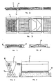
- the plant first of all comprises a system for heating the road coating, formed of several sets of known type metallic panels (diagrammatically illustrated in figure 1 by one panel for each set), onto which panels are installed means for producing infrared rays, consisting for instance of a set of propane gas burners.
- the panels 1 (fig. 1) are driven forward by a self-propelled machine 2, which also comprises a combustible gas tank 3 feeding the burners.
- the same self-propelled machine 2 also tows a second set of panels 4, apt to continue heating the bituminous concrete forming the road coating to be recycled.
- the panels move forward, spaced by about 10 to 20 cm from the road surface to be heated.
- a third set of heating panels 5 is finally driven forward by the main operating machine 6, having a scarifying and recycling function. All the sets of panels are intercalated with panels having no heating elements, but provided with an insulating and reflecting screen.
- the integration of the aggregates contained in the paving layer to be regenerated takes place after the heating by the sets of panels. Said integration is obtained by means of a hopper 7, driven forward by the machine 6 and positioned between this latter and the set of heating panels 5.
- the machine 6 comprises a cylindrical scarifying cutter 8 working on the material forming the road paving, a plant 9 for the addition of asphaltic concrete, a gang of mixers 10 with rotating arms, and a device 11 for levelling the recycled and regenerated material, followed by a normal compactor 12.
- a second hopper 7' identical to the hopper 7, can be optionally towed by the machine 6, said second hopper being designed to contain aggregates for roughening the finished road coating. In this case, such aggregates are spread out onto the regenerated surface, which subsequently undergoes an additional and final tamping by means of a road roller 13.
- FIGS 2 and 3 show part of a set of panels 1, provided with wheels 14, which move forward driven by the self-propelled machine along the paving to be recycled.
- Each of the panels is articulated in 15 to the following panel and it carries the heating elements with infrared rays at a height of 10 to 12 cm from the ground.
- the panels have side curtains 16 (fig. 4), made of thermally insulating material and preventing outward losses of heat from the sides.
- some of these panels do not have elements with infrared rays producing heat, but are instead provided with a thermally insulating and reflecting screen 17 (fig.
- the reflecting panels have their insulating and reflecting screen 17 (fig. 5) at a height of about 5 cm from the surface of the paving to be recycled. This arrangement favours the penetration of heat inside the road coating, simultaneously preventing the coating surface from getting overheated at temperatures which could impair the cortical part of the paving.
- the length and number of the panels are calculated on the basis of the plant running speed, so that the aggregate mass included in the layer extending down to a depth of, for instance, at least 8 cm, may be subjected to a temperature increase of about 100°C in a lapse of time, reckoned as optimal, of about 30 minutes.
- a pair of steering wheels is mounted between the sets of successive panels, in conventional manner, to allowthe assembly to move forward on road bends.
- Said hopper 7 comprises a rotating distributor 18, which is caused to rotate by the self-contained propelling unit 19 positioned outside said hopper, and it moves forward onto the surface previously heated at its highest temperature.
- the propelling unit 19 comprises an explosion engine which operates an oleodynamic pump feeding in turn a hydraulic geared motor.
- the heated surface of the road coating will transmit part of its own heat to the material distributed by the hopper.
- a double advantage is obtained: on one hand, to heat the integrating aggregate which, when getting mixed, thus reaches the most appropriate temperature for a proper working process, by utilizing the heat excess on the coating surface; on the other hand, to obtain a first very efficient mixing between the removed material and the integrating material, thanks to the subsequent action of the cutter 8 which follows.
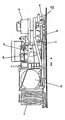
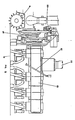
- the scarifying and recycling machine 6 is illustrated in figures 8 and 9. It consists of a self-propelled vehicle, for instance a tracked vehicle, which drives forward the front panels 5 and the hopper 7.
- Said machine comprises a combustible gas tank 20, required to feed burners arranged inside the panels, a driving seat 21, with seats 22 for auxiliary personnel and, in the rear part, the scarifying cylindrical cutter 8, the plant 9 for adding the asphaltic concrete, the mixers 10, the rake 11 for levelling the recycled material, and the tamping bar 12.
- a combustible gas tank 20 required to feed burners arranged inside the panels, a driving seat 21, with seats 22 for auxiliary personnel and, in the rear part, the scarifying cylindrical cutter 8, the plant 9 for adding the asphaltic concrete, the mixers 10, the rake 11 for levelling the recycled material, and the tamping bar 12.
- scarifying cutter or cutters 8 precede the rotary mixers 10, onto which drops the spray of required additional asphaltic concrete, through the pipe 27.
- the rotary mixers 10 are positioned in a gang on two parallel rows, each comprising at least three and preferably four mixers and being arranged along the running direction of the machine. Said gang moves alternately from one side to the other of the lane being worked, and the left row mixers 10 (looking from the rear side of the machine) rotate anticlockwise, while the right row mixers rotate clockwise.
- This arrangement allows to obtain far more satisfactory mixing results than those obtained with the known technique, wherein - as already mentioned - the mixers consist of a single moving row of rotary members or comprise fixed members, and in particular it allows a perfect sharpening and trimming of the edges formed between the lane being worked and the adjacent lanes, thereby guaranteeing a perfect grip of the recycled layer also in correspondence of this particularly difficult position.
- the perfecttrimming of the aforementioned edges can be improved even further by mounting two small vertical cutters (not shown) just downstream of the cylindrical cutter and before the mixers, which are designed to make the surface of said edges perfectly vertical.
- the piston 23 thrusts the scarifying cutter 8 down to the desired depth, extending at least as far as 8 cm.
- the use of the cutter 8, in replacement of the conventional fixed blades mounted on machines of known technique, has been made possible thanks to the particular type of heating adopted, allowing the high temperatures (120°C) to penetrate more deeply inside the road coating. This prevents the action ofthe cutterfrom causing the usual crushing effect of the aggregates, whereby the granulometric curve - as resulting from the tests on the core samples drawn from said coating - keeps perfectly unaltered.
- the articulated joint 24 connects the carriage 25 - onto which are mounted the rotors of the mixers 10,the motor 26 for controlling said rotors, and the pipe 27 for spraying the asphaltic concrete - with the front part of the machine, onto which is mounted the scarifying cutter 8.
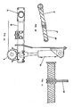
- Figures 10 to 12 show some details of the scarifying cutter 8, which can be formed of a plurality of mutually connected rollers, as 8' and 8" in figures 10 and 11, caused to rotate by the chain 28 (fig. 11) and provided with teeth 29.
- the frame 30 (fig. 12) onto which is mounted the scarifying cutter 8, is articulated in 31 and thrust downwardly to the wanted depth by the piston 23.
- the levelling rake 11 acts in known manner to evenly distribute the regenerated bituminous concrete onto the road surface, and it is followed by the tamping bar 12 which provides for the final settlement of the new recycled coating.
- Said coating can then be subjected - as already said - to the normal finishing operations, particularly roughening and rolling operations, according to the known techniques now adopted in this field.
Landscapes
- Engineering & Computer Science (AREA)
- Architecture (AREA)
- Civil Engineering (AREA)
- Structural Engineering (AREA)
- Mining & Mineral Resources (AREA)
- Processing Of Solid Wastes (AREA)
- Road Repair (AREA)
- Road Paving Structures (AREA)
- Road Paving Machines (AREA)
Claims (10)
Priority Applications (1)
| Application Number | Priority Date | Filing Date | Title |
|---|---|---|---|
| AT84116386T ATE54689T1 (de) | 1984-01-13 | 1984-12-27 | Verfahren und anlage zum heissregenerieren und wiederverwenden an ort und stelle von alten strassendecken. |
Applications Claiming Priority (2)
| Application Number | Priority Date | Filing Date | Title |
|---|---|---|---|
| IT85506/84A IT1181498B (it) | 1984-01-13 | 1984-01-13 | Procedimento di rigenerazione e riciclaggio in sito a caldo delle pavimentazioni stradali usurate e impianto per attuare detto procedimento |
| IT8550684 | 1984-01-13 |
Publications (3)
| Publication Number | Publication Date |
|---|---|
| EP0149848A2 EP0149848A2 (de) | 1985-07-31 |
| EP0149848A3 EP0149848A3 (en) | 1986-12-10 |
| EP0149848B1 true EP0149848B1 (de) | 1990-07-18 |
Family
ID=11327177
Family Applications (1)
| Application Number | Title | Priority Date | Filing Date |
|---|---|---|---|
| EP84116386A Expired - Lifetime EP0149848B1 (de) | 1984-01-13 | 1984-12-27 | Verfahren und Anlage zum Heissregenerieren und Wiederverwenden an Ort und Stelle von alten Strassendecken |
Country Status (4)
| Country | Link |
|---|---|
| EP (1) | EP0149848B1 (de) |
| AT (1) | ATE54689T1 (de) |
| DE (1) | DE3482758D1 (de) |
| IT (1) | IT1181498B (de) |
Families Citing this family (5)
| Publication number | Priority date | Publication date | Assignee | Title |
|---|---|---|---|---|
| FR2634502A1 (fr) * | 1988-07-21 | 1990-01-26 | France Littoral Sa Route | Prechauffeuse extensible et repliage pour regeneration de chaussees et son procede d'utilisation |
| FR2666600B1 (fr) * | 1990-09-07 | 1993-07-23 | Beugnet Sa | Procede de thermorecyclage en place d'une couche de chaussee en enrobes drainants. |
| GB2392190B (en) * | 2002-08-16 | 2005-12-21 | Roads Europ Ltd | Improved road repair systems |
| CN100453735C (zh) * | 2006-04-26 | 2009-01-21 | 鞍山森远路桥股份有限公司 | 沥青路面混合料就地热再生加热器 |
| US10407841B2 (en) | 2017-10-25 | 2019-09-10 | Caterpillar Paving Products Inc. | Rotary mixing system |
Family Cites Families (5)
| Publication number | Priority date | Publication date | Assignee | Title |
|---|---|---|---|---|
| US2254463A (en) * | 1939-06-13 | 1941-09-02 | Spears Wells Machinery Company | Means for constructing and reconstructing road surfaces |
| AT246767B (de) * | 1965-01-29 | 1966-05-10 | Walter Dipl Ing Schimmel | Verfahren zur Instandsetzung von Verkehrsflächen, vorzugsweise Fahrbahnen und Gehwegen, nach Aufgrabungen und Vorrichtung hiefür |
| US3451721A (en) * | 1967-03-06 | 1969-06-24 | Engelhard Hanovia Inc | Combination slotting and milling tool |
| US4347016A (en) * | 1980-08-21 | 1982-08-31 | Sindelar Robert A | Method and apparatus for asphalt paving |
| DE3147834A1 (de) * | 1981-12-03 | 1983-06-16 | Walter 7024 Filderstadt Schölkopf | Verfahren zum instandsetzen einer bituminoesen fahrbahndeckschicht, bei der kontinuierlich das deckschichtmaterial erwaermt, gelockert, eingeebnet und wieder neu verdichtet wird |
-
1984
- 1984-01-13 IT IT85506/84A patent/IT1181498B/it active
- 1984-12-27 EP EP84116386A patent/EP0149848B1/de not_active Expired - Lifetime
- 1984-12-27 AT AT84116386T patent/ATE54689T1/de not_active IP Right Cessation
- 1984-12-27 DE DE8484116386T patent/DE3482758D1/de not_active Expired - Lifetime
Also Published As
| Publication number | Publication date |
|---|---|
| IT1181498B (it) | 1987-09-30 |
| IT8485506A0 (it) | 1984-01-13 |
| DE3482758D1 (de) | 1990-08-23 |
| EP0149848A3 (en) | 1986-12-10 |
| EP0149848A2 (de) | 1985-07-31 |
| ATE54689T1 (de) | 1990-08-15 |
Similar Documents
| Publication | Publication Date | Title |
|---|---|---|
| US4793730A (en) | Asphalt surface renewal method and apparatus | |
| RU2121031C1 (ru) | Способ рециркуляции асфальтового покрытия и устройство для его осуществления | |
| US5653552A (en) | Process for heating an asphalt surface | |
| US4129398A (en) | Method and apparatus for plastifying and tearing up of damaged road-surfaces and covers | |
| US4784518A (en) | Double-stage repaving method and apparatus | |
| US3997276A (en) | Road maintenance machine and methods | |
| US7588388B2 (en) | Paved surface reconditioning system | |
| US5484224A (en) | Method of resurfacing an asphalt surface | |
| GB1600260A (en) | Microwave method and apparatus for heating pavements | |
| CN105442423A (zh) | 用于加热铣刨机上的铣刨喷洒搅拌收料集成装置 | |
| US20060127180A1 (en) | Apparatus and method for working asphalt pavement | |
| EP0149848A2 (de) | Verfahren und Anlage zum Heissregenerieren und Wiederverwenden an Ort und Stelle von alten Strassendecken | |
| CN105755935A (zh) | 一种微波就地热再生成套设备 | |
| RU2593669C1 (ru) | Дорожная машина | |
| CN205711659U (zh) | 一种微波就地热再生成套设备 | |
| Shoenberger et al. | Hot-in-place recycling of asphalt pavements | |
| CA2321062A1 (en) | Machine and method for the renewal of an asphalt surface | |
| DE10325064A1 (de) | Verfahren zum Instandsetzen von Straßen mit Spurrillen und Straßenbaueinheit | |
| CN100350101C (zh) | 沥青路面软化翻修机 | |
| US2002661A (en) | Machine for paving highways | |
| RU2794576C1 (ru) | Способ ямочного ремонта асфальтобетонных покрытий и устройства для его реализации | |
| CA1094375A (en) | Method and apparatus for plastifying and tearing up of damaged road-surfaces and covers | |
| CN113584988A (zh) | 一种废旧沥青混合料高比例厂拌热再生路面及施工工法 | |
| RU2550017C1 (ru) | Способ ремонта автозимников | |
| Dowdy | Hot in-Place Recycling of Asphalt Pavements. |
Legal Events
| Date | Code | Title | Description |
|---|---|---|---|
| PUAI | Public reference made under article 153(3) epc to a published international application that has entered the european phase |
Free format text: ORIGINAL CODE: 0009012 |
|
| AK | Designated contracting states |
Designated state(s): AT BE CH DE FR GB IT LI LU NL SE |
|
| PUAL | Search report despatched |
Free format text: ORIGINAL CODE: 0009013 |
|
| AK | Designated contracting states |
Kind code of ref document: A3 Designated state(s): AT BE CH DE FR GB IT LI LU NL SE |
|
| 17P | Request for examination filed |
Effective date: 19870427 |
|
| 17Q | First examination report despatched |
Effective date: 19880406 |
|
| GRAA | (expected) grant |
Free format text: ORIGINAL CODE: 0009210 |
|
| AK | Designated contracting states |
Kind code of ref document: B1 Designated state(s): AT BE CH DE FR GB IT LI LU NL SE |
|
| PG25 | Lapsed in a contracting state [announced via postgrant information from national office to epo] |
Ref country code: SE Effective date: 19900718 |
|
| REF | Corresponds to: |
Ref document number: 54689 Country of ref document: AT Date of ref document: 19900815 Kind code of ref document: T |
|
| REF | Corresponds to: |
Ref document number: 3482758 Country of ref document: DE Date of ref document: 19900823 |
|
| ET | Fr: translation filed | ||
| ITF | It: translation for a ep patent filed | ||
| PG25 | Lapsed in a contracting state [announced via postgrant information from national office to epo] |
Ref country code: LU Free format text: LAPSE BECAUSE OF NON-PAYMENT OF DUE FEES Effective date: 19901231 |
|
| PLBE | No opposition filed within time limit |
Free format text: ORIGINAL CODE: 0009261 |
|
| STAA | Information on the status of an ep patent application or granted ep patent |
Free format text: STATUS: NO OPPOSITION FILED WITHIN TIME LIMIT |
|
| 26N | No opposition filed | ||
| ITTA | It: last paid annual fee | ||
| REG | Reference to a national code |
Ref country code: GB Ref legal event code: IF02 |
|
| PGFP | Annual fee paid to national office [announced via postgrant information from national office to epo] |
Ref country code: FR Payment date: 20031223 Year of fee payment: 20 |
|
| PGFP | Annual fee paid to national office [announced via postgrant information from national office to epo] |
Ref country code: NL Payment date: 20031224 Year of fee payment: 20 Ref country code: GB Payment date: 20031224 Year of fee payment: 20 |
|
| PGFP | Annual fee paid to national office [announced via postgrant information from national office to epo] |
Ref country code: CH Payment date: 20031229 Year of fee payment: 20 |
|
| PGFP | Annual fee paid to national office [announced via postgrant information from national office to epo] |
Ref country code: AT Payment date: 20031230 Year of fee payment: 20 |
|
| PGFP | Annual fee paid to national office [announced via postgrant information from national office to epo] |
Ref country code: BE Payment date: 20040115 Year of fee payment: 20 |
|
| PGFP | Annual fee paid to national office [announced via postgrant information from national office to epo] |
Ref country code: DE Payment date: 20040122 Year of fee payment: 20 |
|
| PG25 | Lapsed in a contracting state [announced via postgrant information from national office to epo] |
Ref country code: LI Free format text: LAPSE BECAUSE OF EXPIRATION OF PROTECTION Effective date: 20041226 Ref country code: GB Free format text: LAPSE BECAUSE OF EXPIRATION OF PROTECTION Effective date: 20041226 Ref country code: CH Free format text: LAPSE BECAUSE OF EXPIRATION OF PROTECTION Effective date: 20041226 |
|
| PG25 | Lapsed in a contracting state [announced via postgrant information from national office to epo] |
Ref country code: NL Free format text: LAPSE BECAUSE OF EXPIRATION OF PROTECTION Effective date: 20041227 |
|
| BE20 | Be: patent expired |
Owner name: *SOAVE ASFALTI S.P.A. Effective date: 20041227 |
|
| REG | Reference to a national code |
Ref country code: GB Ref legal event code: PE20 |
|
| REG | Reference to a national code |
Ref country code: CH Ref legal event code: PL |
|
| NLV7 | Nl: ceased due to reaching the maximum lifetime of a patent |
Effective date: 20041227 |