EP0150000A2 - Dispositif de manoeuvre de volet roulant comme système modulaire pour commande à gland, à manivelle et électrique - Google Patents
Dispositif de manoeuvre de volet roulant comme système modulaire pour commande à gland, à manivelle et électrique Download PDFInfo
- Publication number
- EP0150000A2 EP0150000A2 EP85100092A EP85100092A EP0150000A2 EP 0150000 A2 EP0150000 A2 EP 0150000A2 EP 85100092 A EP85100092 A EP 85100092A EP 85100092 A EP85100092 A EP 85100092A EP 0150000 A2 EP0150000 A2 EP 0150000A2
- Authority
- EP
- European Patent Office
- Prior art keywords
- roller shutter
- gear
- roller
- belt
- crank
- Prior art date
- Legal status (The legal status is an assumption and is not a legal conclusion. Google has not performed a legal analysis and makes no representation as to the accuracy of the status listed.)
- Granted
Links
- 238000010276 construction Methods 0.000 title 1
- 230000005540 biological transmission Effects 0.000 claims abstract description 27
- 230000001681 protective effect Effects 0.000 claims abstract description 22
- 230000008878 coupling Effects 0.000 claims description 40
- 238000010168 coupling process Methods 0.000 claims description 40
- 238000005859 coupling reaction Methods 0.000 claims description 40
- 238000005253 cladding Methods 0.000 claims description 15
- 238000009434 installation Methods 0.000 claims description 9
- 239000002184 metal Substances 0.000 claims description 6
- 230000007246 mechanism Effects 0.000 claims description 5
- 230000000007 visual effect Effects 0.000 claims description 4
- 238000007789 sealing Methods 0.000 claims description 3
- 238000005096 rolling process Methods 0.000 claims description 2
- 238000004804 winding Methods 0.000 claims description 2
- 238000009413 insulation Methods 0.000 claims 1
- 230000036316 preload Effects 0.000 claims 1
- 230000003287 optical effect Effects 0.000 description 3
- 230000007480 spreading Effects 0.000 description 2
- 238000003892 spreading Methods 0.000 description 2
- 238000013475 authorization Methods 0.000 description 1
- 230000004323 axial length Effects 0.000 description 1
- 230000000903 blocking effect Effects 0.000 description 1
- 230000008859 change Effects 0.000 description 1
- 230000000694 effects Effects 0.000 description 1
- 239000012774 insulation material Substances 0.000 description 1
- 238000004519 manufacturing process Methods 0.000 description 1
- 239000000463 material Substances 0.000 description 1
- 238000012986 modification Methods 0.000 description 1
- 230000004048 modification Effects 0.000 description 1
- 238000000465 moulding Methods 0.000 description 1
- 230000009467 reduction Effects 0.000 description 1
- 231100000241 scar Toxicity 0.000 description 1
Images





Classifications
-
- E—FIXED CONSTRUCTIONS
- E06—DOORS, WINDOWS, SHUTTERS, OR ROLLER BLINDS IN GENERAL; LADDERS
- E06B—FIXED OR MOVABLE CLOSURES FOR OPENINGS IN BUILDINGS, VEHICLES, FENCES OR LIKE ENCLOSURES IN GENERAL, e.g. DOORS, WINDOWS, BLINDS, GATES
- E06B9/00—Screening or protective devices for wall or similar openings, with or without operating or securing mechanisms; Closures of similar construction
- E06B9/56—Operating, guiding or securing devices or arrangements for roll-type closures; Spring drums; Tape drums; Counterweighting arrangements therefor
- E06B9/80—Safety measures against dropping or unauthorised opening; Braking or immobilising devices; Devices for limiting unrolling
- E06B9/82—Safety measures against dropping or unauthorised opening; Braking or immobilising devices; Devices for limiting unrolling automatic
- E06B9/88—Safety measures against dropping or unauthorised opening; Braking or immobilising devices; Devices for limiting unrolling automatic for limiting unrolling
-
- E—FIXED CONSTRUCTIONS
- E06—DOORS, WINDOWS, SHUTTERS, OR ROLLER BLINDS IN GENERAL; LADDERS
- E06B—FIXED OR MOVABLE CLOSURES FOR OPENINGS IN BUILDINGS, VEHICLES, FENCES OR LIKE ENCLOSURES IN GENERAL, e.g. DOORS, WINDOWS, BLINDS, GATES
- E06B9/00—Screening or protective devices for wall or similar openings, with or without operating or securing mechanisms; Closures of similar construction
- E06B9/56—Operating, guiding or securing devices or arrangements for roll-type closures; Spring drums; Tape drums; Counterweighting arrangements therefor
- E06B9/68—Operating devices or mechanisms, e.g. with electric drive
- E06B9/70—Operating devices or mechanisms, e.g. with electric drive comprising an electric motor positioned outside the roller
-
- E—FIXED CONSTRUCTIONS
- E06—DOORS, WINDOWS, SHUTTERS, OR ROLLER BLINDS IN GENERAL; LADDERS
- E06B—FIXED OR MOVABLE CLOSURES FOR OPENINGS IN BUILDINGS, VEHICLES, FENCES OR LIKE ENCLOSURES IN GENERAL, e.g. DOORS, WINDOWS, BLINDS, GATES
- E06B9/00—Screening or protective devices for wall or similar openings, with or without operating or securing mechanisms; Closures of similar construction
- E06B9/56—Operating, guiding or securing devices or arrangements for roll-type closures; Spring drums; Tape drums; Counterweighting arrangements therefor
- E06B9/68—Operating devices or mechanisms, e.g. with electric drive
- E06B9/76—Operating devices or mechanisms, e.g. with electric drive using crank handles
-
- E—FIXED CONSTRUCTIONS
- E06—DOORS, WINDOWS, SHUTTERS, OR ROLLER BLINDS IN GENERAL; LADDERS
- E06B—FIXED OR MOVABLE CLOSURES FOR OPENINGS IN BUILDINGS, VEHICLES, FENCES OR LIKE ENCLOSURES IN GENERAL, e.g. DOORS, WINDOWS, BLINDS, GATES
- E06B9/00—Screening or protective devices for wall or similar openings, with or without operating or securing mechanisms; Closures of similar construction
- E06B9/56—Operating, guiding or securing devices or arrangements for roll-type closures; Spring drums; Tape drums; Counterweighting arrangements therefor
- E06B9/78—Operating, guiding or securing devices or arrangements for roll-type closures; Spring drums; Tape drums; Counterweighting arrangements therefor for direct manual operation, e.g. by tassels, by handles
-
- E—FIXED CONSTRUCTIONS
- E06—DOORS, WINDOWS, SHUTTERS, OR ROLLER BLINDS IN GENERAL; LADDERS
- E06B—FIXED OR MOVABLE CLOSURES FOR OPENINGS IN BUILDINGS, VEHICLES, FENCES OR LIKE ENCLOSURES IN GENERAL, e.g. DOORS, WINDOWS, BLINDS, GATES
- E06B9/00—Screening or protective devices for wall or similar openings, with or without operating or securing mechanisms; Closures of similar construction
- E06B9/56—Operating, guiding or securing devices or arrangements for roll-type closures; Spring drums; Tape drums; Counterweighting arrangements therefor
- E06B9/80—Safety measures against dropping or unauthorised opening; Braking or immobilising devices; Devices for limiting unrolling
- E06B9/82—Safety measures against dropping or unauthorised opening; Braking or immobilising devices; Devices for limiting unrolling automatic
- E06B9/86—Safety measures against dropping or unauthorised opening; Braking or immobilising devices; Devices for limiting unrolling automatic against unauthorised opening
-
- E—FIXED CONSTRUCTIONS
- E06—DOORS, WINDOWS, SHUTTERS, OR ROLLER BLINDS IN GENERAL; LADDERS
- E06B—FIXED OR MOVABLE CLOSURES FOR OPENINGS IN BUILDINGS, VEHICLES, FENCES OR LIKE ENCLOSURES IN GENERAL, e.g. DOORS, WINDOWS, BLINDS, GATES
- E06B9/00—Screening or protective devices for wall or similar openings, with or without operating or securing mechanisms; Closures of similar construction
- E06B9/56—Operating, guiding or securing devices or arrangements for roll-type closures; Spring drums; Tape drums; Counterweighting arrangements therefor
- E06B9/68—Operating devices or mechanisms, e.g. with electric drive
- E06B2009/6809—Control
- E06B2009/6872—Control using counters to determine shutter position
- E06B2009/6881—Mechanical counters
-
- E—FIXED CONSTRUCTIONS
- E06—DOORS, WINDOWS, SHUTTERS, OR ROLLER BLINDS IN GENERAL; LADDERS
- E06B—FIXED OR MOVABLE CLOSURES FOR OPENINGS IN BUILDINGS, VEHICLES, FENCES OR LIKE ENCLOSURES IN GENERAL, e.g. DOORS, WINDOWS, BLINDS, GATES
- E06B9/00—Screening or protective devices for wall or similar openings, with or without operating or securing mechanisms; Closures of similar construction
- E06B9/56—Operating, guiding or securing devices or arrangements for roll-type closures; Spring drums; Tape drums; Counterweighting arrangements therefor
- E06B9/78—Operating, guiding or securing devices or arrangements for roll-type closures; Spring drums; Tape drums; Counterweighting arrangements therefor for direct manual operation, e.g. by tassels, by handles
- E06B2009/785—Operating, guiding or securing devices or arrangements for roll-type closures; Spring drums; Tape drums; Counterweighting arrangements therefor for direct manual operation, e.g. by tassels, by handles by belts, straps, bands, tapes, cords, tassels
-
- E—FIXED CONSTRUCTIONS
- E06—DOORS, WINDOWS, SHUTTERS, OR ROLLER BLINDS IN GENERAL; LADDERS
- E06B—FIXED OR MOVABLE CLOSURES FOR OPENINGS IN BUILDINGS, VEHICLES, FENCES OR LIKE ENCLOSURES IN GENERAL, e.g. DOORS, WINDOWS, BLINDS, GATES
- E06B9/00—Screening or protective devices for wall or similar openings, with or without operating or securing mechanisms; Closures of similar construction
- E06B9/56—Operating, guiding or securing devices or arrangements for roll-type closures; Spring drums; Tape drums; Counterweighting arrangements therefor
- E06B9/80—Safety measures against dropping or unauthorised opening; Braking or immobilising devices; Devices for limiting unrolling
- E06B2009/801—Locking arrangements
- E06B2009/802—Locking arrangements located in or close to shutter box
Definitions
- the invention relates to a roller shutter actuation device as a modular system for belt-pull crank and electric drive, the existing drive can be replaced by another drive without removing the roller shutter roller and the belt being guided invisibly with belt-pull drive, and the crank drive also for roller shutter drives are installed in roller shutter boxes that are not part of the modular system, can be used and all types of actuation have a roller shutter lock.
- roller shutter actuators on the market are designed in most cases only for one or two different drive types. In all cases, when changing the drive type, the roller shutter roller must be removed, which is very costly and time-consuming.
- the belt When the belt is pulled, the belt is guided visibly on the inside of the wall of the room and runs in an unfavorable position of the belt reel in the roller shutter box to the wall belt box, diagonally over the wall. This looks very unattractive and leads to rapid wear of the webbing.
- the crank linkages that hang down from the roller shutter box also have a very disturbing effect and are very bulky.
- the invention has for its object to provide a novel device of the type mentioned in such a way that the roller shutter head piece can be used for different thicknesses of cladding profiles, a subsequent change of the drive types belt tension, crank, and electric drive allows without removing the roller shutter roller when pulling the belt Belt and the crank linkage in the crank drive are not visible, the crank drive should also be used for drives of roller shutters that are mounted in roller shutter boxes that do not belong to this modular system.
- the electric drive should already be pre-assembled on a gear plate, which is subsequently screwed onto fastening elements already in the roller shutter head piece.
- Each drive type should have a roller shutter lock that blocks the roller shutter from being lifted or pulled down.
- the roller shutter head piece consists of a roller shutter roller bearing part with two corner pieces, which serve on the one hand to limit and abut the cladding profiles and on which on the other hand a roller shutter safety device is attached in such a way that a pivotable base plate with a roller shutter armor guide element is mounted over that the roller shutter armor slides when rolling up and down.
- a clamping piece is rotatably and resiliently mounted on the base plate in such a way that the roller shutter curtain glides unhindered when the roller curtain roller moves.
- roller shutter lock can also be installed with any other roller shutter.
- the train is secured by Blocking of the roller shutter roller, which is described in more detail below.
- the two other corner pieces are interchangeable and at the same time serve to accommodate a cam which is actuated by the belt pulley, with which an optical or acoustic warning device can also be switched on via a switch.
- the interchangeable head plate which can be assigned to the respective thickness of the roller shutter cladding profiles, is screwed to the roller shutter head piece.
- the roller shutter roller has a belt pulley with laterally attached spur gear teeth, wherein the toothed ring can also have internal teeth and forms a unit with the belt pulley.
- the belt When using a belt pull, the belt is guided through a deflection part, which is located on the roller shutter head piece, and through the door or window frame. At the actuation height, the belt emerges from the frame, is only visible in the grip width and is guided with the belt roller cover. There is a space between the belt and the belt reel cover, which allows the belt to be pulled easily.
- the belt is fed to the belt reel under the belt reel cover with belt tension coil spring via a rotatably mounted clamping lever, which clamps the belt in the direction of the belt guide when there is a tensile load.
- the switch that switches on the acoustic or visual warning system is located on the cover plate of the belt reel cover. This warning system can also be installed in the crank mechanism.
- a flexible shaft which is provided with a protective hose, connects the bevel gear of the transmission gear plug-in with a crank deflection gear, which is attached at crank height and has a wrap or spreading spring turnstile between the crank deflection gear and the articulated hand crank, which only blocks all rotary movements transmitted by the flexible shaft.
- the flexible shaft is guided through the hollow profile of the metal or plastic frame or through a groove in the wooden frame.
- the roller shutter head piece and an installation housing for the crank deflection gear are connected with a connecting tube, which is used to hold the flexible shaft.
- a roller shutter stroke limiting device can be installed in the respective transmission gear and the flexible shaft.
- This stroke limiting device consists of a spindle with a fine thread, the length of which corresponds to the maximum movement path of a roller shutter, the path of a spindle nut that can only move in the axial direction is limited by a nut that can be locked in the axial direction, the setting of which is adapted to the roller shutter stroke path required in each case.
- the gearbox which is already pre-assembled in the factory on a gear plate, has a wrap or spreading spring lock between the gear wheel, which is in engagement with the toothing located on the belt pulley, and the pinion ratio of the electric motor, which prevents the rotary movements occurring on the part of the belt pulley blocked, as well as a stroke limitation control, consisting of a spindle, which is connected to the gear via a gear and a spindle nut located thereon, which is only axially movable and actuates the two switches that control the roller shutter path, one switch being slidably arranged to to make the roller shutter path adjustable.
- this complete gear unit can be screwed onto the screw-on elements already in the roller shutter head piece in parallel or axially aligned with the roller shutter roller.
- the gear frame is designed so that the outer contour corresponds to the corner pieces to give the roller shutter cladding profiles the necessary support, as well as the flexible shaft with the protective tube on the upper gear frame part is attached. Furthermore, the rotatably mounted holding plate with the roller shutter armor guide part and the spring-loaded roller shutter armor clamping lever is shown in the open guide position.
- roller shutter head piece 3 shows a cross section through the roller shutter head piece, consisting of the roller shutter roller bearing part, in which the roller shutter roller is mounted with the belt pulley attached to it, which has at least one spur gear toothing on the roller shutter head piece side, and the exchangeable head piece plate in a small version for fastening the roller shutter Cladding profiles.
- Figure 4 shows a cross section through the roller shutter head piece, consisting of the roller shutter roller bearing part and the replaceable head piece plate in a larger version for fastening roller shutter - cladding profiles with sound and heat insulating plates attached to the inside.
- Figure 5 shows a cross section through the metal or plastic door or window frame, which on the frame - wall connection side has a groove, in which the protective tube and the flexible shaft located therein is guided and which is closed with a groove - sealing strip.
- FIG. 7 shows a front view of the roller shutter head piece with the connecting tube laid on the wall to the installation housing of the crank deflection gear.
- FIG. 8 shows a side view of the roller shutter head piece with a longitudinal section of the connecting pipe laid in the wall and the protective hose located in the connecting pipe and the flexible shaft guided therein, as well as the crank deflection gear installed in the installation housing.
- Figure 10 is a plan view of the screw-on gear part of the transmission gear consisting of a gear frame, a spur gear bevel gear unit, the spur gear establishes the connection to the spur gear of the belt pulley, and another bevel gear which is in engagement with the bevel gear of the spur gear bevel gear unit and its scar with the flexible shaft is positively connected.
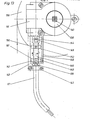
- FIG. 11 shows a cross section through the crank deflection gear with the wrap spring rotary lock arranged between the crank deflection gear and the articulated hand crank.
- FIG. 12 shows a cross section through the coupling part that connects the articulated hand crank to the crank deflection gear.
- Figure 13 is a side view of the slip-on transmission gear with the adapter part that connects the slip-on transmission gear with the flexible shaft and to which the protective hose of the flexible shaft is attached, as well as the roller shutter stroke limiting device that can be optionally installed in the adapter part.
- Figure 14 shows a section of the side view of the roller shutter roller bearing part with the gear plate, which is screwed to the fasteners of the corner pieces.
- Figure 15 is a view of the gear unit mounted on the gear plate, consisting of at least two gear stages located between the electric motor and the spur gear of the belt pulley and a wrap spring rotary lock arranged between them, and a control spindle connected to the gear unit, the spindle nut of which actuates two limit switches which are assigned to the beginning and end of the roller shutter stroke, with a limit switch being arranged displaceably and being adjustable according to the roller shutter length.
- Figure 16 is a view of the gear unit mounted on the gear plate, which is screwed axially in alignment with the roller shutter roller on the roller shutter roller bearing part and whose gear is connected via a pinion to the internal spur gear teeth of the belt pulley.
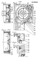
- roller shutter head piece 1 shows a roller shutter head piece 1 of a roller shutter box 2, which is fastened to a door or window frame 3 with suitable means and whose roller shutter armor 4 is actuated with a tension belt 5.
- This roller shutter head piece 1 consists of the roller shutter roller bearing part 6, which has support surfaces 7, 8, 9 on the roller shutter side for supporting the cladding profiles 10, 11, 12, and the guide lugs 13 and 14 for sliding on the tension belt deflection part 15, and the unscrewable ones Corner pieces 16, 17, which serve with their support surfaces 18, 19 and 20, 21 to support the cladding profiles 12, 22 and 11.
- the corner pieces 16 and 17 have the bolts 23, 24 and the guide lugs 25, 26 and 27, 28.
- a cam disk 33 is rotatably mounted, which has a spur gear toothing 34 on the roller shutter head piece side, which is in engagement with the spur gear toothing 35 of the belt pulley 36, which is also located on the roller shutter head piece side and forms a unit with the belt pulley 36 .
- the switch 38 is actuated when the belt disk 36 rotates, which triggers a warning signal after an optical or acoustic warning device has been switched on.
- roller shutter curtain 4 which is fastened to the roller shutter roller 39 by suitable means and is secured against pulling down by unauthorized pulling on the roller shutter curtain 4 by the blocked tension belt 5, is deflected by the roller shutter roller 39 via the roller shutter curtain guide element 40 which is rigidly attached to the pivotable base plate 41, and the roller shutter rail 42 is listed.
- the clamping piece 44 Above the roller shutter armor element 43 sliding over the roller shutter armor guide element 40, the clamping piece 44 is rotatably mounted on the base plate 41, the clamping arm 45 of which is pressed with the leg spring 46 against the stop 47, which is arranged such that the roller shutter armor 4 is unobstructed by actuating the roller shutter actuating device can slide through.
- the clamping piece 44 and its clamping arm 45 are designed such that when the roller shutter curtain elements 43 are pushed up, they fold over at the deflection point 48 and thus press the clamping arm 45 upwards, as a result of which the roller shutter curtain 4 is clamped at the clamping point 49 and thus blocks the roller shutter curtain 4 and prevents it from being pushed up.
- This roller shutter securing device is attached to the roller shutter head piece 1 on both sides of the roller shutter armor 4 and can also be used with other roller shutter head pieces as a roller shutter securing device with an adapter part (not shown).
- the tension belt 5 is coming from the belt reel 36 through the tension belt - deflection element 15 - which is fastened with its guide grooves to the guide lugs 13 and 25 - and through the hollow profile of the door or window frame 3, deflected via a support part 50 and through the Opening 51 in the belt reel cover 52 is guided outwards in such a way that a grip space 54 for pulling the tension belt 5 is formed between the visible belt piece 53 and the belt reel cover 52.
- Via the rotatably mounted clamping lever 55 the tension belt between the clamping axis 56 and the clamping plate 57 is fed to the belt latch 58 with the belt tension spiral spring 59.
- the switch 61 for switching on the warning device is located below the belt reel 58 in the cover plate 60 of the belt reel cover 52.
- the replaceable header plate 62 i which is connected to the roller shutter headpiece 1 and serves to fasten the cladding profiles 10, 11, 12 and 22.
- FIG. 2 shows the roller shutter head piece 1 of the roller shutter box 2, the corner piece 16 and the tension belt deflection part 15 removed (FIG. 1) is replaced by the deflection gear 62 2 which is described in more detail in FIGS. 9 and 10 and the spur gear 63 with the spur gear teeth 35 the belt pulley 36 is engaged.
- the upper gear plate 64 is designed so that it serves with its side surfaces 65, 66 to support the cladding profiles 13 and 22 and to which the protective tube 67 of the flexible shaft 68 is fastened with the clamp 69. With this reversing gear 62, the belt tension drive can be replaced by a crank drive with gear reduction without removing the roller shutter roller 39.
- FIG. 3 shows the roller shutter roller bearing part 6 with the roller shutter roller 39 mounted therein, on which the belt pulley 36, with the spur gear toothing 35 present on the roller shutter head piece side, where an internal toothing 70 may also be located under this toothing, is non-positively and positively connected.
- the interchangeable roller shutter head plate 62 is screwed into its smallest size on the rear side of the roller shutter roller bearing part 6.
- FIG. 4 shows the roller shutter roller bearing part 6 in connection with a roller shutter head plate 71, which has larger external dimensions than the roller shutter head plate 62 and is provided on all sides with the circumferential support web 72, which makes it possible to use different cladding profiles, which are provided on the inside with sound and heat insulation materials 74 of different thicknesses.
- FIG. 5 shows a cross section through a hollow profile 75 through a metal or plastic door or window frame, through the large hollow chamber 76 of which the flexible shaft 68 with the protective tube 67 is guided.
- FIG. 6 shows a cross section through a profile 77 of a wooden door or window frame which has a groove 78 which is introduced from the wall connection side 79 to accommodate the flexible shaft 68 with the protective tube 67 and after the flexible shaft 68 has been received the protective tube 67 is closed with a sealing strip 80.
- FIG. 8 shows a side view of the roller shutter head piece 1, with the connecting pipe 82 laid in the masonry 81 - for receiving the flexible shaft 68 with the protective hose 67 - to the installation housing 83, which has a pipe - connecting piece 85 for connection to the connecting pipe 82, and a screw-on plate 86 with preformed holes 87 for fastening the crank deflection gear 84.
- the connecting tube 82 serves to receive control lines and the installation housing 83 of the front plate with the switching elements, which is not shown here.
- the protective tube 67 surrounding the flexible shaft 68 is fastened in a rotationally and tension-proof manner on the guide plate 93 of the gear plate 64 with the clamp 69.
- the articulated hand crank 119 has the fork joint arm 124, the fork 125 of which is arranged offset by 90 ° to the fork 126, and can be pulled apart telescopically, both parts being pushed together as in FIG pulled apart state, are held with a releasable snap connection (this is not shown in the drawing).
- the hand crank intermediate piece 127 has the flat shaped parts 128, 129 which are arranged in alignment with one another, the flat shaped part 128 being pivotably mounted in the fork 126 and the flat shaped part 129 in the fork 130 of the hand crank part 131.
Landscapes
- Engineering & Computer Science (AREA)
- Structural Engineering (AREA)
- Architecture (AREA)
- Civil Engineering (AREA)
- Operating, Guiding And Securing Of Roll- Type Closing Members (AREA)
Priority Applications (1)
| Application Number | Priority Date | Filing Date | Title |
|---|---|---|---|
| AT85100092T ATE55804T1 (de) | 1984-01-10 | 1985-01-06 | Rolladenbetaetigungsvorrichtung als baukastensystem fuer gurtzug-kurbel- und elektroantrieb. |
Applications Claiming Priority (4)
| Application Number | Priority Date | Filing Date | Title |
|---|---|---|---|
| DE3400528 | 1984-01-10 | ||
| DE3400528 | 1984-01-10 | ||
| DE3436890 | 1984-10-08 | ||
| DE3436890 | 1984-10-08 |
Publications (3)
| Publication Number | Publication Date |
|---|---|
| EP0150000A2 true EP0150000A2 (fr) | 1985-07-31 |
| EP0150000A3 EP0150000A3 (en) | 1986-03-12 |
| EP0150000B1 EP0150000B1 (fr) | 1990-08-22 |
Family
ID=25817456
Family Applications (1)
| Application Number | Title | Priority Date | Filing Date |
|---|---|---|---|
| EP19850100092 Expired - Lifetime EP0150000B1 (fr) | 1984-01-10 | 1985-01-06 | Dispositif de manoeuvre de volet roulant comme système modulaire pour commande à gland, à manivelle et électrique |
Country Status (1)
| Country | Link |
|---|---|
| EP (1) | EP0150000B1 (fr) |
Cited By (4)
| Publication number | Priority date | Publication date | Assignee | Title |
|---|---|---|---|---|
| US5609196A (en) * | 1993-10-11 | 1997-03-11 | Kraler; Franz | Roller blind system |
| US5655587A (en) * | 1993-10-11 | 1997-08-12 | Kraler; Franz | Roller blind system |
| ES2154113A1 (es) * | 1996-03-15 | 2001-03-16 | Fuertes Justo Miedes | Sistema de accionamiento de persianas de lamas enrollables. |
| CN108386118A (zh) * | 2018-04-20 | 2018-08-10 | 瑞安市雅木窗饰有限公司 | 一种百叶窗帘 |
Family Cites Families (5)
| Publication number | Priority date | Publication date | Assignee | Title |
|---|---|---|---|---|
| DE2415738A1 (de) * | 1974-04-01 | 1975-10-16 | Home Fertigelemente Gmbh | Rolladenkasten |
| DE2514283A1 (de) * | 1975-04-02 | 1976-10-21 | Paul Spahr | Nothandkurbeltrieb fuer elektrisch angetriebene rolltore, rolladen, rollgitter o.dgl. |
| DE7625001U1 (de) * | 1976-08-09 | 1976-11-25 | Helge, Hans, Tossa De Mar, Gerona (Spanien) | Bausatz fuer einen rolladenkasten insbesondere fuer altbauten |
| DE7806067U1 (de) * | 1978-03-01 | 1978-07-06 | Dyna-Plastik-Werke Gmbh, 5060 Bergisch Gladbach | Rolladenkasten |
| DE8226980U1 (de) * | 1982-09-25 | 1983-02-10 | Ernst Selve GmbH & Co KG, 5880 Lüdenscheid | Halterung fuer einen rolladenantrieb |
-
1985
- 1985-01-06 EP EP19850100092 patent/EP0150000B1/fr not_active Expired - Lifetime
Cited By (5)
| Publication number | Priority date | Publication date | Assignee | Title |
|---|---|---|---|---|
| US5609196A (en) * | 1993-10-11 | 1997-03-11 | Kraler; Franz | Roller blind system |
| US5655587A (en) * | 1993-10-11 | 1997-08-12 | Kraler; Franz | Roller blind system |
| ES2154113A1 (es) * | 1996-03-15 | 2001-03-16 | Fuertes Justo Miedes | Sistema de accionamiento de persianas de lamas enrollables. |
| CN108386118A (zh) * | 2018-04-20 | 2018-08-10 | 瑞安市雅木窗饰有限公司 | 一种百叶窗帘 |
| CN108386118B (zh) * | 2018-04-20 | 2024-01-19 | 瑞安市雅木窗饰有限公司 | 一种百叶窗帘 |
Also Published As
| Publication number | Publication date |
|---|---|
| EP0150000A3 (en) | 1986-03-12 |
| EP0150000B1 (fr) | 1990-08-22 |
Similar Documents
| Publication | Publication Date | Title |
|---|---|---|
| EP0526522B1 (fr) | Fermeture a levier pivotant verrouillee par une serrure a pompe | |
| DE69602799T2 (de) | Manuell freigebbare Kupplung zur Verbindung einer langgestreckten Betätigungsvorrichtung mit einem Flügelrahmen u. ein schwenkbares Fenster mit Kettenbetätigung und einer solchen Kupplung | |
| EP1818490A2 (fr) | Dispositif d'actionnement pour portes | |
| DE4230729A1 (de) | Vorrichtung zur antriebsabschaltung des motors elektrisch betriebener rollaeden, rolltore, markisen o. dgl. | |
| EP0601454A1 (fr) | Store à enrouleur pour véhicule | |
| EP1921233A1 (fr) | Entraînement de commande pouvant être rééquipé pour une porte pivotante ou analogue | |
| DE19518493C2 (de) | Antriebseinrichtung für ein Torblatt | |
| EP1002923A2 (fr) | Dispositif d'ouverture et de fermeture d'une ouverture dans une paroi au moyen d'une porte coulissante | |
| EP0725204B1 (fr) | Dispositif de commande électrique pour une sangle d'un volet à rouleau ou des choses pareilles | |
| EP1964700B1 (fr) | Store de fenêtre de véhicule | |
| EP0150000A2 (fr) | Dispositif de manoeuvre de volet roulant comme système modulaire pour commande à gland, à manivelle et électrique | |
| DE29817616U1 (de) | Torwellenantriebsaggregat für Tore mit einer Antriebs- und/oder Torsionsfeder-Welle | |
| EP1865130A1 (fr) | Agencement de déverrouillage d'une fenêtre, d'une porte ou analogue | |
| DE3500285A1 (de) | Rolladenbetaetigungsvorrichtung als baukastensystem fuer gurtzug- kurbel- und elektroantrieb | |
| AT1463U1 (de) | Antriebsanordnung für verdrehbare lamellen eines eine fenster- oder türöffnung abdeckenden ladens | |
| EP0610948A1 (fr) | Appareil pour l'ouverture et la fermeture mécanique de fenêtres avec ferrure cachée | |
| DE10058483B4 (de) | Selbst sperrende Verriegelungseinrichtung für Flügel mit Überschlag | |
| DE1244609B (de) | Vorrichtung zum elektromotorischen Bewegen von vorzugsweise lotrecht schiebbaren Fenstern, insbesondere von Kraftfahrzeugen | |
| DE1555632B2 (fr) | ||
| DE102006059224A1 (de) | Antrieb für Drehflügeltüren | |
| DE3151224A1 (de) | Vorrichtung zur befestigung eines getriebes an einem rahmen von fenstern, tueren oder dergleichen | |
| DE4200868A1 (de) | Zusatz-schliesseinrichtung fuer fenster | |
| EP0374271B1 (fr) | Dispositif de commande d'une porte coulissant horizontalement sur des poulies le long d'un rail de guidage | |
| EP1746235B1 (fr) | Ensemble de ferrure | |
| DE19617740C1 (de) | Vorrichtung zur Antriebsabschaltung des Motors elektrisch betriebener Markisen, Markisoletten u. dgl. |
Legal Events
| Date | Code | Title | Description |
|---|---|---|---|
| PUAI | Public reference made under article 153(3) epc to a published international application that has entered the european phase |
Free format text: ORIGINAL CODE: 0009012 |
|
| AK | Designated contracting states |
Designated state(s): AT BE CH FR GB IT LI NL SE |
|
| PUAL | Search report despatched |
Free format text: ORIGINAL CODE: 0009013 |
|
| AK | Designated contracting states |
Kind code of ref document: A3 Designated state(s): AT BE CH FR GB IT LI NL SE |
|
| 17P | Request for examination filed |
Effective date: 19860911 |
|
| 17Q | First examination report despatched |
Effective date: 19880624 |
|
| GRAA | (expected) grant |
Free format text: ORIGINAL CODE: 0009210 |
|
| AK | Designated contracting states |
Kind code of ref document: B1 Designated state(s): AT BE CH FR GB IT LI NL SE |
|
| PG25 | Lapsed in a contracting state [announced via postgrant information from national office to epo] |
Ref country code: SE Free format text: THE PATENT HAS BEEN ANNULLED BY A DECISION OF A NATIONAL AUTHORITY Effective date: 19900822 Ref country code: NL Effective date: 19900822 Ref country code: IT Free format text: LAPSE BECAUSE OF FAILURE TO SUBMIT A TRANSLATION OF THE DESCRIPTION OR TO PAY THE FEE WITHIN THE PRESCRIBED TIME-LIMIT;WARNING: LAPSES OF ITALIAN PATENTS WITH EFFECTIVE DATE BEFORE 2007 MAY HAVE OCCURRED AT ANY TIME BEFORE 2007. THE CORRECT EFFECTIVE DATE MAY BE DIFFERENT FROM THE ONE RECORDED. Effective date: 19900822 Ref country code: GB Effective date: 19900822 Ref country code: FR Effective date: 19900822 Ref country code: BE Effective date: 19900822 |
|
| REF | Corresponds to: |
Ref document number: 55804 Country of ref document: AT Date of ref document: 19900915 Kind code of ref document: T |
|
| PG25 | Lapsed in a contracting state [announced via postgrant information from national office to epo] |
Ref country code: AT Effective date: 19910106 |
|
| EN | Fr: translation not filed | ||
| PG25 | Lapsed in a contracting state [announced via postgrant information from national office to epo] |
Ref country code: LI Effective date: 19910131 Ref country code: CH Effective date: 19910131 |
|
| NLV1 | Nl: lapsed or annulled due to failure to fulfill the requirements of art. 29p and 29m of the patents act | ||
| GBV | Gb: ep patent (uk) treated as always having been void in accordance with gb section 77(7)/1977 [no translation filed] | ||
| PLBE | No opposition filed within time limit |
Free format text: ORIGINAL CODE: 0009261 |
|
| STAA | Information on the status of an ep patent application or granted ep patent |
Free format text: STATUS: NO OPPOSITION FILED WITHIN TIME LIMIT |
|
| 26N | No opposition filed | ||
| REG | Reference to a national code |
Ref country code: CH Ref legal event code: PL |