EP0150046A2 - Bracelet pour pièce d'horlogerie - Google Patents
Bracelet pour pièce d'horlogerie Download PDFInfo
- Publication number
- EP0150046A2 EP0150046A2 EP85100437A EP85100437A EP0150046A2 EP 0150046 A2 EP0150046 A2 EP 0150046A2 EP 85100437 A EP85100437 A EP 85100437A EP 85100437 A EP85100437 A EP 85100437A EP 0150046 A2 EP0150046 A2 EP 0150046A2
- Authority
- EP
- European Patent Office
- Prior art keywords
- sleeve
- bracelet
- teeth
- strand
- clasp
- Prior art date
- Legal status (The legal status is an assumption and is not a legal conclusion. Google has not performed a legal analysis and makes no representation as to the accuracy of the status listed.)
- Withdrawn
Links
Images
Classifications
-
- B—PERFORMING OPERATIONS; TRANSPORTING
- B65—CONVEYING; PACKING; STORING; HANDLING THIN OR FILAMENTARY MATERIAL
- B65D—CONTAINERS FOR STORAGE OR TRANSPORT OF ARTICLES OR MATERIALS, e.g. BAGS, BARRELS, BOTTLES, BOXES, CANS, CARTONS, CRATES, DRUMS, JARS, TANKS, HOPPERS, FORWARDING CONTAINERS; ACCESSORIES, CLOSURES, OR FITTINGS THEREFOR; PACKAGING ELEMENTS; PACKAGES
- B65D63/00—Flexible elongated elements, e.g. straps, for bundling or supporting articles
- B65D63/10—Non-metallic straps, tapes, or bands; Filamentary elements, e.g. strings, threads or wires; Joints between ends thereof
- B65D63/1018—Joints produced by application of integral securing members, e.g. buckles, wedges, tongue and slot, locking head and teeth or the like
- B65D63/1027—Joints produced by application of integral securing members, e.g. buckles, wedges, tongue and slot, locking head and teeth or the like the integral securing member being formed as a female and male locking member, e.g. locking head and locking teeth, or the like
- B65D63/1063—Joints produced by application of integral securing members, e.g. buckles, wedges, tongue and slot, locking head and teeth or the like the integral securing member being formed as a female and male locking member, e.g. locking head and locking teeth, or the like the female locking member being provided with at least one plastic barb
- B65D63/1072—Joints produced by application of integral securing members, e.g. buckles, wedges, tongue and slot, locking head and teeth or the like the integral securing member being formed as a female and male locking member, e.g. locking head and locking teeth, or the like the female locking member being provided with at least one plastic barb the barb having a plurality of serrations
-
- A—HUMAN NECESSITIES
- A44—HABERDASHERY; JEWELLERY
- A44C—PERSONAL ADORNMENTS, e.g. JEWELLERY; COINS
- A44C5/00—Bracelets; Wrist-watch straps; Fastenings for bracelets or wrist-watch straps
- A44C5/0053—Flexible straps
-
- A—HUMAN NECESSITIES
- A44—HABERDASHERY; JEWELLERY
- A44C—PERSONAL ADORNMENTS, e.g. JEWELLERY; COINS
- A44C5/00—Bracelets; Wrist-watch straps; Fastenings for bracelets or wrist-watch straps
- A44C5/18—Fasteners for straps, chains or the like
- A44C5/20—Fasteners for straps, chains or the like for open straps, chains or the like
- A44C5/2076—Fasteners for straps, chains or the like for open straps, chains or the like with the two ends of the strap or chain abutting each other or sliding in the main plane or a plane parallel to the main plane of these two ends
-
- Y—GENERAL TAGGING OF NEW TECHNOLOGICAL DEVELOPMENTS; GENERAL TAGGING OF CROSS-SECTIONAL TECHNOLOGIES SPANNING OVER SEVERAL SECTIONS OF THE IPC; TECHNICAL SUBJECTS COVERED BY FORMER USPC CROSS-REFERENCE ART COLLECTIONS [XRACs] AND DIGESTS
- Y10—TECHNICAL SUBJECTS COVERED BY FORMER USPC
- Y10T—TECHNICAL SUBJECTS COVERED BY FORMER US CLASSIFICATION
- Y10T24/00—Buckles, buttons, clasps, etc.
- Y10T24/14—Bale and package ties, hose clamps
- Y10T24/1402—Packet holders
- Y10T24/1406—Adjustable bands
-
- Y—GENERAL TAGGING OF NEW TECHNOLOGICAL DEVELOPMENTS; GENERAL TAGGING OF CROSS-SECTIONAL TECHNOLOGIES SPANNING OVER SEVERAL SECTIONS OF THE IPC; TECHNICAL SUBJECTS COVERED BY FORMER USPC CROSS-REFERENCE ART COLLECTIONS [XRACs] AND DIGESTS
- Y10—TECHNICAL SUBJECTS COVERED BY FORMER USPC
- Y10T—TECHNICAL SUBJECTS COVERED BY FORMER US CLASSIFICATION
- Y10T24/00—Buckles, buttons, clasps, etc.
- Y10T24/14—Bale and package ties, hose clamps
- Y10T24/1498—Plastic band
-
- Y—GENERAL TAGGING OF NEW TECHNOLOGICAL DEVELOPMENTS; GENERAL TAGGING OF CROSS-SECTIONAL TECHNOLOGIES SPANNING OVER SEVERAL SECTIONS OF THE IPC; TECHNICAL SUBJECTS COVERED BY FORMER USPC CROSS-REFERENCE ART COLLECTIONS [XRACs] AND DIGESTS
- Y10—TECHNICAL SUBJECTS COVERED BY FORMER USPC
- Y10T—TECHNICAL SUBJECTS COVERED BY FORMER US CLASSIFICATION
- Y10T24/00—Buckles, buttons, clasps, etc.
- Y10T24/15—Bag fasteners
- Y10T24/153—Plastic band bag tie
Definitions
- the present invention relates to a bracelet for a timepiece.
- a cable harness clamp which comprises a clasp comprising a sleeve defining a passage which extends longitudinally relative to the strand of the collar to which it is attached and in which can be inserted the other strand of the collar, one of the faces of this other strand being provided with a toothing whose teeth extend transversely and cooperate with the teeth of a complementary toothing provided in the sleeve so as to be able be locked by snap-fastening on the teeth of the sleeve, the latter being transversely deformable to allow the snap-fastening to be released when the collar is opened.
- this collar and more precisely of its clasp makes it suitable for playing the role for which it is intended, that is to say to hold the cables together in a bundle and also to allow the collar to be loosened in case the beam needs to be changed for any reason.
- the collar has a relatively small width so that, when the sleeve is deformed laterally when the collar is opened, it takes a shape of circular section, which easily releases the teeth one of the other.
- the invention consists precisely in creating a bracelet for a timepiece whose basic design is taken from the aforementioned prior art, but which is adapted in a particular way to make it usable for this purpose.
- the invention therefore relates to such a bracelet which comprises a clasp comprising a sleeve defining a passage which extends longitudinally with respect to the strand of the bracelet to which it is attached and into which the other strand of the bracelet, the one of the faces of this other strand being provided with a toothing whose teeth extend transversely and cooperate with the teeth of a complementary toothing provided in the sleeve so as to be able to be locked by snap-fastening on the teeth of the sleeve, the latter being deformable transversely to allow the latching to be released when the bracelet is opened, characterized in that the teeth of the sleeve are provided on the wall portion of the latter which is contiguous to the wrist when the bracelet is in place on the latter and in that the toothing of said other strand is on the face thereof facing towards the wrist.
- the bracelet according to the invention has the advantage of being able to be produced practically in one piece by injection molding and therefore of requiring very few assembly operations. In addition, it has a pleasant appearance.
- Figure 1 is a perspective view of a bracelet 1 according to the invention attached to a timepiece P. It has strands 2 and 3 whose free ends opposite to the timepiece P form a clasp 4
- the strand 3 has at its free end a sleeve 5 which defines a passage extending longitudinally relative to the length of the bracelet.
- the middle zones of the ends of the strands 2 and 3 are respectively provided with snap-fit teeth 6 and 7.
- the portion 8 of the sleeve 5 of the strand 3 opposite to the snap-back teeth 7 has longitudinal ribs 9, 10, 11 and 12 which extend inwards against the latching teeth 7, these ribs being intended to facilitate guiding the other strand 2 in the sleeve 5.
- a rectangular opening 13 is provided, the extent of which corresponds to the surface of the latching teeth 7. This opening 13 is intended to allow the fixing of the latching teeth 7 during the manufacture of the bracelet 1.
- FIG 2 there is shown a longitudinal sectional view of the clasp 4.
- the sleeve 5 protrudes from the general plane of the strand 3 on the outside, that is to say away from the wrist of the user, when the bracelet is in place.
- the toothing 7 is on the wall portion of the sleeve 5 which is contiguous to the wrist, as is the toothing formed by the teeth 6 which are formed on the other strand 2.
- the strands 2 and 3 can also be produced as attachments, that is to say be mounted as in the case of many conventional clasps. But advantageously the band-like extensions 14 and 15 of the clasp can be made directly to the desired length to form the bracelet. It is visible in the figure% that the front flanks 16 and 17 as well as the rear flanks 18 and 19 of the snap-fit teeth 6 and 7 have a shape such that they do with the planes parallel to the parts 14 and 15 in the form of strip angles other than 90 °.
- This sawtooth embodiment of teeth 6 and 7 has the advantage that the strand 2 can very easily be inserted into the sleeve 5 whereas, on the contrary, the withdrawal, that is to say an unexpected opening of the clasp, n is not possible.
- Figure 4 shows a cross-sectional view of the clasp in the closed configuration.
- FIG. 5 there is also shown a cross-sectional view of the clasp 4.
- the latching teeth 7 are released from the teeth 6 of the strand 2 due to the elastic deformation property of the sleeve 5.
- the strands 2 and 3 having an inherent tendency to deviate from one another so as to assume an almost flat shape, that is to say to constantly stress their free ends in the direction of the arrows F 1 in FIGS. 1, 2 and 5, it is clear that the teeth formed by the teeth 6 and 7 are in turn urged so as to disengage from one another, when by pressure lateral in the direction of the arrows F 2 (FIG. 5), the sleeve 5 is deformed.
- the teeth are only provided in the longitudinal middle parts of the strand 2, respectively of the sleeve 5, so that even at the lateral ends of their edges the teeth cannot catch on.
- the sleeve 5 returns to its initial shape so as to be ready to receive the strand 2 again.
- the sleeve 5 is provided on the side of the wrist instead of being located outside.
- the position of the teeth remains identical so that the same advantageous properties are inherent in this variant.
- This also has the advantage of keeping the strand 2 inside the loop formed by the bracelet, that is to say between the strand 3 and the wrist, which makes a possible sliding loop unnecessary. usually provided to maintain this strand.
- the clasp can be adjusted practically continuously, that is to say in steps corresponding to the distance between two snap-fit teeth which can be of about 2 mm.
- the adjustment can be carried out for example by introducing a nail between two teeth and then sliding the strand 2 in the sleeve 5.
- the clasp can be produced in two parts whereas the conventional snap-fasteners require at least six parts.
- the manufacture can be carried out by an injection operation of a suitable thermo-plastic material such as polyurethane.
Landscapes
- Engineering & Computer Science (AREA)
- Mechanical Engineering (AREA)
- Adornments (AREA)
Abstract
Le fermoir (4) de ce bracelet (1) comporte un manchon (5) attaché à l'un des brins (3). Le manchon comporte des dents transversales (7) disposées sur une portion de paroi du manchon contiguë au poignet. Ces dents coopèrent avec des dents complémentaires (6) ménagées sur l'autre brin (2) du bracelet. Le manchon (5) est élastiquement déformable dans le sens transversal pour permettre le dégagement des dents les unes des autres et ainsi l'ouverture du bracelet.
Celui-ci peut être réalisé en une seule pièce à partir d'une matière plastique telle que le polyuréthane.
Description
- La présente invention concerne un bracelet pour pièce d'horlogerie.
- D'après le brevet US-A-2 979 794 on connaît un collier de serrage pour faisceau de câbles qui comprend un fermoir comportant un manchon définissant un passage qui s'étend longitudinalement par rapport au brin du collier auquel il est attaché et dans lequel peut être inséré l'autre brin du collier, l'une des faces de cet autre brin étant pourvue d'une denture dont les dents s'étendent transversalement et coopèrent avec les dents d'une denture complémentaire prévue dans le manchon de manière à pouvoir se bloquer par encliquetage sur les dents du manchon, ce dernier étant déformable transversalement pour permettre le déblocage de l'encliquetage lors de l'ouverture du collier.
- L'agencement de ce collier et plus précisément de son fermoir le rend apte à jouer le rôle pour lequel il est destiné, c'est-à-dire de tenir assemblés les câbles d'un faisceau et de permettre en outre le desserrage du collier au cas où le faisceau doit être modifié pour une raison ou une autre. Il en est ainsi parce que le collier présente une largeur relativement faible de sorte que, lorsque le manchon est déformé latéralement lors de l'ouverture du collier, il prend une forme de section circulaire, ce qui dégage sans difficulté les dentures l'une de l'autre.
- Si on tente d'appliquer la construction de ce collier de serrage à la fabrication d'un bracelet pour pièce d'horlogerie, on aura d'emblée tendance à augmenter la largeur des brins pour leur donner une dimension usuelle en horlogerie. Cependant, ce faisant, on se heurte à des difficultés lors de l'ouverture du bracelet (toutes choses étant égales par ailleurs) car lors de la déformation latérale du manchon qui a alors une section nettement plus large que haute, ce manchon s'ovalise en déformant localement les bords du brin qui y est introduit. Dans ces conditions, les dentures ne peuvent se dégager l'une de l'autre car les arêtes des dents restent en prise surtout à leurs deux extrémités, c'est-à-dire près des bords latéraux du manchon. Ce défaut est d'ailleurs d'autant plus prononcé que le bracelet est plus serré autour du poignet de l'utilisateur.
- Un autre facteur qui aggrave encore ce phénomène est que les brins du bracelet ont tendance, de par leur élasticité propre, à s'écarter l'une de l'autre lorsqu'ils ne sont pas attachés par le fermoir. De ce fait, les dentures sont sollicitées à s'interpénétrer ce qui est favorable pour la tenue du collier contre une ouverture intempestive, mais ce qui en revanche ne facilite pas cette ouverture lorsqu'on veut l'effectuer à dessein. En effet, lorsque le manchon est déformé latéralement pour l'ouverture, les dentures continuent à être sollicitées dans le même sens à savoir à s'accrocher l'une dans l'autre.
- On conçoit que ces défauts de la technique antérieure surgissant lorsqu'on veut l'appliquer à un bracelet de pièce d'horlogerie n'incitent guère le spécialiste à l'utiliser dans ce but particulier.
- Or, l'invention consiste précisément à créer un bracelet pour pièce d'horlogerie dont la conception de base est tirée de la technique antérieure précitée, mais qui est adaptée de façon particulière pour la rendre utilisable dans ce but.
- L'invention a donc pour objet un tel bracelet qui comprend un fermoir comportant un manchon définissant un passage qui s'étend longitudinalement par rapport au brin du bracelet auquel il est attaché et dans lequel peut être inséré l'autre brin du bracelet, l'une des faces de cet autre brin étant pourvue d'une denture dont les dents s'étendent transversalement et coopèrent avec les dents d'une denture complémentaire prévue dans le manchon de manière à pouvoir se bloquer par encliquetage sur les dents du manchon, ce dernier étant déformable transversalement pour permettre le déblocage de l'encliquetage lors de l'ouverture du bracelet, caractérisé en ce que les dents du manchon sont prévues sur la portion de paroi de celui-ci qui est contiguë au poignet lorsque le bracelet est en place sur ce dernier et en ce que la denture dudit autre brin se trouve sur la face de celui-ci tournée vers le poignet.
- Il résulte de ces caractéristiques que l'ouverture du bracelet se fait toujours sans problèmes, car lorsque le manchon est déformé latéralement, l'élasticité propre du brin qui y est inséré a tendance à écarter les dentures l'une de l'autre, même dans le cas où la largeur du bracelet est comparativement importante.
- Le bracelet suivant l'invention présente l'avantage de pouvoir être fabriqué pratiquement en une seule pièce par moulage par injection et donc de ne nécessiter que très peu d'opérations de montage. En outre, il a un aspect agréable à la vue.
- L'invention sera mieux comprise à la lecture de la description qui va suivre, donnée uniquement à titre d'exemple et faite en se référant aux dessins annexés sur lesquels :
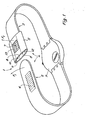
- la figure 1 est une vue en perspective d'un bracelet suivant l'invention;
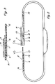
- la figure 2 est une vue en coupe longitudinale du fermoir en position ouverte;
- la figure 3 est une vue en coupe longitudinale du fermoir en position fermée;
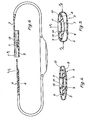
- les figures 4 et 5 montrent des vues en coupe transversale du fermoir, respectivement en position fermée et juste avant son ouverture;
- la figure 6 est une vue en coupe longitudinale d'un autre mode de réalisation.
- La figure 1 est une vue en perspective d'un bracelet 1 conforme à l'invention attaché à une pièce d'horlogerie P. Il comporte des brins 2 et 3 dont les extrémités libres opposées à la pièce d'horlogerie P forment un fermoir 4. Le brin 3 comporte à son extrémité libre un manchon 5 qui définit un passage s'étendant longitudinalement par rapport à la longueur du bracelet. Les zones médianes des extrémités des brins 2 et 3 sont respectivement pourvues de dents d'encliquetage 6 et 7. La portion 8 du manchon 5 du brin 3 opposée aux dents d'encliquetage 7 présente des nervures longitudinales 9, 10, 11 et 12 qui s'étendent vers l'intérieur contre les dents d'encliquetage 7, ces nervures étant destinées à facili'ter le guidage de l'autre brin 2 dans le manchon 5. Dans la portion 8 supérieure opposée aux dents d'encliquetage 7 du manchon 5, il est prévu une ouverture rectangulaire 13 dont l'étendue correspond à la surface des dents d'encliquetage 7. Cette ouverture 13 est destinée à permettre la fixation des dents d'encliquetage 7 au cours de la fabrication du bracelet 1.
- Sur la figure 2, on a représenté une vue en coupe longitudinale du fermoir 4. On voit que le manchon 5 est en saillie du plan général du brin 3 du côté extérieur, c'est-à-dire éloigné du poignet de l'utilisateur, lorsque le bracelet est en place. On voit également clairement que la denture 7 se trouve sur la portion de paroi du manchon 5 qui est contiguë au poignet comme l'est d'ailleurs la denture formée par les dents 6 qui sont ménagées sur l'autre brin 2.
- Au lieu de former partie intégrante du bracelet, et suivant une variante, les brins 2 et 3 peuvent également être réalisés comme pièces rapportées, c'est-à-dire être montés comme dans le cas de nombreux fermoirs classiques. Mais avantageusement les prolongements en forme de bande 14 et 15 du fermoir peuvent être réalisés directement à la longueur souhaitée pour former le bracelet. Il est visible sur la figure % que les flancs avant 16 et 17 ainsi que les flancs arrière 18 et 19 des dents d'encliquetage 6 et 7 ont une forme telle qu'ils fassent avec les plans parallèles aux parties 14 et 15 en forme de bande des angles différents de 90°. Cette réalisation en dents de scie des dents 6 et 7 présente l'avantage que le brin 2 peut très facilement être inséré dans le manchon 5 alors qu'au contraire le retrait, c'est-à-dire une ouverture inopinée du fermoir, n'est pas possible.
- Sur la figure 3, on a représenté une coupe longitudinale du fermoir dans sa configuration fermée.
- La figure 4 montre une vue en coupe transversale du fermoir en configuration fermée.
- A la figure 5, on a représenté également une vue en coupe transversale du fermoir 4. En effectuant une pression par exemple avec l'index et le pouce dans le sens des flèches F2 sur le manchon 5, les dents d'encliquetage 7 sont dégagées des dents 6 du brin 2 en raison de la propriété de déformation élastique du manchon 5.
- Les brins 2. et 3 ayant tendance eux-mêmes de façon inhérente à s'écarter l'un de l'autre de manière à assumer une forme à peu près plate, c'est-à-dire à solliciter constamment leurs extrémités libres dans le sens des flèches F1 sur les figures 1, 2 et 5, il est clair que les dentures formées par les dents 6 et 7 sont à leur tour sollicitées de manière à se dégager l'une de l'autre, lorsque par une pression latérale dans le sens des flèches F2 (figure 5), le manchon 5 est déformé. On peut alors simplement retirer le brin 2 du manchon 5, sans qu'en aucune manière, les dentures gênent ce mouvement. A cela s'ajoute que les dentures ne sont prévues que dans les parties médianes longitudinales du brin 2, respectivement du manchon 5, si bien que même aux extrémités latérales de leurs arêtes les dents ne peuvent pas s'accrocher. Bien entendu, après le retrait du brin 2, le manchon 5 reprend sa forme initiale pour être prêt à recevoir de nouveau le brin 2.
- Dans le mode de réalisation de la figure 6, le manchon 5 est prévu du côté du poignet au lieu d'être situé à l'extérieur. Toutefois, on remarquera que la position des dentures demeure identique de sorte que les mêmes propriétés avantageuses sont inhérentes à cette variante. Celle-ci a d'ailleurs l'avantage de maintenir le brin 2 à l'intérieur de la boucle formée par le bracelet, c'est-à-dire entre le brin 3 et le poignet, ce qui rend inutile un éventuel passant coulissant habituellement prévu pour maintenir ce brin.
- Un autre avantage considérable du fermoir que l'on vient de décrire consiste en ce qu'on peut le régler pratiquement en continu, c'est-à-dire par pas correspondant à la distance entre deux dents d'encliquetage qui peut être d'environ 2 mm. Le réglage peut être effectué par exemple en introduisant un ongle entre deux dents et en faisant coulisser ensuite le brin 2 dans le manchon 5. Le fermoir peut être réalisé en deux parties alors que les fermoirs à encliquetage classiques nécessitent au moins six pièces. En outre, la fabrication peut être réalisée en une opération d'injection d'une matière thermo-plastique appropriée telle que le polyuréthane.
- On notera enfin que pour ouvrir le fermoir 4, il faut nécessairement appliquer une force dans le sens des flèches F2 des deux côtés du manchon 5 (figure 5) sans quoi les dentures ne peuvent se dégager. Il est donc impossible que le bracelet s'ouvre lorsqu'on heurte latéralement le fermoir.
Claims (6)
1. Bracelet pour pièce d'horlogerie qui comprend un fermoir (4) comportant un manchon (5) définissant un passage qui s'étend longitudinalement par rapport au brin (3) du bracelet auquel il est attaché et dans lequel peut être inséré l'autre brin (2) du bracelet, l'une des faces de cet autre brin (2) étant pourvue d'une denture dont les dents (6) s'étendent transversalement et coopèrent avec les dents (7) d'une denture complémentaire prévue dans le manchon (5) de manière à pouvoir se bloquer par encliquetage sur les dents (7) du manchon (5), ce dernier étant déformable transversalement pour permettre le déblocage de l'encliquetage lors de l'ouverture du bracelet, celui-ci étant caractérisé en ce que les dents (7) du manchon (5) sont prévues sur la portion de paroi de celui-ci qui est contiguë au poignet lorsque le bracelet est en place sur ce dernier et en ce que la denture (6) dudit autre brin (2) se trouve sur la face de celui-ci tournée vers le poignet.
2. Bracelet suivant la revendication 1, caractérisé en ce que les dents (6, 7) des dentures prévues respectivement sur ledit autre brin (2) et ledit manchon (5) sont disposées dans des parties longitudinales médianes de ceux-ci.
3. Bracelet suivant l'une quelconque des revendications 1 et 2, caractérisé en ce que des nervures longitudinales (9 à 12) sont ménagées sur la portion de paroi du manchon (5) opposée à celle sur laquelle sont prévues les dents (7) de ce manchon (5).
4. Bracelet suivant l'une quelconque des revendications 1 à 3, caractérisé en ce que les deux flancs des dents (6, 7) prévues respectivement sur ledit autre brin (2) et ledit manchon (5) font avec des plans parallèles auxdits brins (2, 3) des angles différents de 90°.
5. Bracelet suivant l'une quelconque des revendications 1 à 4, caractérisé en ce que ledit manchon (5) est ménagé du côté du poignet de l'utilisateur.
6. Bracelet suivant l'une quelconque des revendications 1 à 4, caractérisé en ce que ledit manchon (5) est ménagé du côté extérieur du bracelet.
Applications Claiming Priority (2)
| Application Number | Priority Date | Filing Date | Title |
|---|---|---|---|
| CH265/84 | 1984-01-20 | ||
| CH26584 | 1984-01-20 |
Publications (2)
| Publication Number | Publication Date |
|---|---|
| EP0150046A2 true EP0150046A2 (fr) | 1985-07-31 |
| EP0150046A3 EP0150046A3 (fr) | 1985-09-11 |
Family
ID=4183063
Family Applications (1)
| Application Number | Title | Priority Date | Filing Date |
|---|---|---|---|
| EP85100437A Withdrawn EP0150046A3 (fr) | 1984-01-20 | 1985-01-17 | Bracelet pour pièce d'horlogerie |
Country Status (3)
| Country | Link |
|---|---|
| US (1) | US4615185A (fr) |
| EP (1) | EP0150046A3 (fr) |
| JP (1) | JPS60241402A (fr) |
Cited By (10)
| Publication number | Priority date | Publication date | Assignee | Title |
|---|---|---|---|---|
| EP0378867A1 (fr) * | 1989-01-19 | 1990-07-25 | Compagnia Nazionale S.P.A. | Montre-bracelet |
| EP0444238A1 (fr) * | 1990-02-28 | 1991-09-04 | JUWELIER WILHELM RüSCHENBECK | Bracelet-montre avec fermoir |
| FR2663694A1 (fr) * | 1990-06-22 | 1991-12-27 | Dubled Bernard | Dispositif d'attache pour la fixation mutuelle de deux objets. |
| WO1992017088A1 (fr) * | 1991-03-27 | 1992-10-15 | Hirsch Armbänder Gesellschaft M.B.H. | Bracelet de montre |
| DE4223720A1 (de) * | 1991-08-06 | 1993-02-11 | Alberts Gmbh & Co Kg G | Einschlagbodenhuelse |
| GB2290940A (en) * | 1994-07-05 | 1996-01-17 | Decca Jewellery Company Limite | Adjustable bracelet |
| EP0893360A1 (fr) * | 1997-07-21 | 1999-01-27 | Bowthorpe Plc | Collier de serrage en matière plastique ayant un mécanisme d' ouverture |
| WO2008025569A1 (fr) * | 2006-09-01 | 2008-03-06 | Hellermann Tyton Gmbh | Attache-câble |
| CN106535694A (zh) * | 2014-07-21 | 2017-03-22 | 微软技术许可有限责任公司 | 可调节带机制 |
| FR3071136A1 (fr) * | 2017-09-20 | 2019-03-22 | Commissariat A L'energie Atomique Et Aux Energies Alternatives | Sangle de serrage type bracelet de montre |
Families Citing this family (62)
| Publication number | Priority date | Publication date | Assignee | Title |
|---|---|---|---|---|
| JPH0520166Y2 (fr) * | 1984-09-19 | 1993-05-26 | ||
| FR2579427B1 (fr) * | 1985-04-02 | 1987-06-12 | Ebauchesfabrik Eta Ag | Article de fantaisie |
| JPS61170307U (fr) * | 1985-04-10 | 1986-10-22 | ||
| US4837959A (en) * | 1986-03-03 | 1989-06-13 | Celico Joseph M A | Marker device |
| USD301120S (en) | 1986-05-27 | 1989-05-16 | Bel Air Tool Corp. | Earring |
| US4941236A (en) * | 1989-07-06 | 1990-07-17 | Timex Corporation | Magnetic clasp for wristwatch strap |
| US4951362A (en) * | 1989-09-11 | 1990-08-28 | Dek, Inc. | Low profile bag clamp |
| US5377387A (en) * | 1993-02-25 | 1995-01-03 | Freed; Anna B. | Two-way adjustable tie |
| IT230921Y1 (it) * | 1993-04-15 | 1999-07-05 | Nordica Spa | Strutture di dispositivo di aggancio,particolarmente per fasce dentate per calzature sportive |
| JP2602582Y2 (ja) * | 1993-10-13 | 2000-01-17 | 株式会社キャットアイ | 自転車用取付部品 |
| GB2310130B (en) * | 1993-11-20 | 1997-12-17 | Roger Anderson | Key carrier |
| USD390803S (en) | 1995-04-26 | 1998-02-17 | Artime SA | Wristwatch buckle |
| US5605262A (en) * | 1995-06-01 | 1997-02-25 | Bond; James R. | Adjustable wrist band |
| US5810854A (en) * | 1997-01-24 | 1998-09-22 | Beach; William R. | Method and apparatus for attaching connective tissue to each other or underlying bone |
| US6085550A (en) * | 1998-02-09 | 2000-07-11 | Ishida; Mitsugi | Adjustable article of jewelry and related method |
| DE19832671C2 (de) * | 1998-07-21 | 2001-11-29 | Skidata Ag | Elektronischer Datenträger |
| US6003714A (en) * | 1998-08-11 | 1999-12-21 | Buermann; Henry | Compressed gas cylinder safety cap and valve seal retainer |
| US6119314A (en) * | 1999-03-09 | 2000-09-19 | Freed; Anna B. | Multi-function tie |
| FR2804841B1 (fr) * | 2000-02-11 | 2002-06-21 | Amine Hassani | Dispositif d'assemblage de deux extremites de bandes souples et procede de fabrication d'un tel dispositif |
| US6332223B1 (en) * | 2000-04-05 | 2001-12-25 | Gray Matter Holdings, Llc | Apparatus and method for making an ear warmer having interior seams |
| CA2858544C (fr) * | 2000-12-29 | 2018-01-30 | 180S, Inc. | Dispositif de protection pour les oreilles |
| US6467132B1 (en) * | 2001-04-24 | 2002-10-22 | Spencer Hart Robley | Band for securing items and method of use |
| US20030099162A1 (en) | 2001-11-29 | 2003-05-29 | Field Jean Marie | Snag-free wrist watch |
| US6735784B2 (en) | 2002-01-28 | 2004-05-18 | 180S, Inc. | Apparatus and method for making an ear warmer and an ear warmer frame |
| MC200057A1 (fr) * | 2002-03-22 | 2003-01-30 | Albert Hazan | Anneau et bijou à modules interchangeables et ajustables |
| EP1618434A4 (fr) * | 2003-04-24 | 2006-09-27 | Alphamicron Inc | Accessoires a cristaux liquides |
| US7212645B2 (en) | 2003-08-12 | 2007-05-01 | 180S, Inc. | Ear warmer with a speaker system |
| US7650649B2 (en) | 2003-08-12 | 2010-01-26 | 180S, Inc. | Ear warmer having an external frame |
| US7962970B2 (en) | 2003-08-12 | 2011-06-21 | 180S, Inc. | Ear warmer having a curved ear portion |
| US7222373B2 (en) | 2003-08-12 | 2007-05-29 | 180S, Inc. | Ear warmer having a membrane forming a receptacle |
| CA105900S (en) | 2003-08-12 | 2006-10-19 | 180S Inc | Frame for ear warmer |
| USD551576S1 (en) | 2006-09-22 | 2007-09-25 | Gerald Field | Watch |
| US8443466B2 (en) | 2007-01-22 | 2013-05-21 | 180S, Inc. | Ear protection device |
| TWM326400U (en) * | 2007-03-06 | 2008-02-01 | Swepo Co Ltd | Structure of identifying ring |
| USD581826S1 (en) * | 2007-11-30 | 2008-12-02 | Nike, Inc. | Portion of a watch |
| US8011124B1 (en) * | 2008-10-28 | 2011-09-06 | Safe And Secure Legacy, Llc | Bracelet identification system and method |
| DE202010004150U1 (de) | 2009-04-08 | 2010-10-07 | Klingenberg, Uwe, Dipl.-Kfm. | Kennzeichnungsband zur Kennzeichnung einer Person |
| DE102010012217A1 (de) | 2010-03-19 | 2011-09-22 | Uwe Klingenberg | Kennzeichnungsband zur Kennzeichnung einer Person und Verfahren zur Herstellung eines Kennzeichnungsbandes |
| DE102009016508B4 (de) * | 2009-04-08 | 2013-07-04 | Uwe Klingenberg | Band zur Befestigung am Handgelenk einer zu kennzeichnenden Person |
| US8029185B2 (en) * | 2009-05-28 | 2011-10-04 | Quiksilver, Inc. | Apparatus for securing and adjusting a watch strap |
| US20110056241A1 (en) * | 2009-09-04 | 2011-03-10 | Bosco Li | Spring lock mechanism for hinged pierced earring |
| AU2010202398B2 (en) * | 2009-09-18 | 2011-11-17 | Makedo Pty Ltd | Releasable locking clip |
| US8250797B2 (en) * | 2010-03-01 | 2012-08-28 | Disney Enterprises, LLC | Two-piece wristband with slidable extension for user-selectable sizing |
| EP2458458B1 (fr) * | 2010-11-26 | 2017-11-15 | The Swatch Group Research and Development Ltd. | Procédé de mesure de la précision d'une montre mécanique |
| KR101782773B1 (ko) | 2013-03-15 | 2017-09-27 | 애플 인크. | 부착 장치 및 관련된 사용 및 제조 방법 |
| US20140315455A1 (en) * | 2013-04-22 | 2014-10-23 | Hannes Simon Hänska | Leash mount and releasable leash system |
| IL230112B (en) * | 2013-12-23 | 2018-03-29 | Alexander Fedan | Alarm clock |
| US10016029B2 (en) * | 2014-08-09 | 2018-07-10 | Apple Inc. | Attachment systems for electronic devices |
| US9894964B2 (en) | 2014-08-11 | 2018-02-20 | Apple Inc. | Consumer product attachment systems having a locking assembly |
| US10085523B2 (en) | 2014-08-11 | 2018-10-02 | Apple Inc. | Attachment system for an electronic device |
| US10184506B2 (en) | 2014-08-11 | 2019-01-22 | Apple Inc. | Captive elements of an attachment system |
| US20160066842A1 (en) * | 2014-09-09 | 2016-03-10 | Polar Electro Oy | Wrist-worn apparatus for optical heart rate measurement |
| US9949537B2 (en) | 2015-03-06 | 2018-04-24 | Apple Inc. | Clasp mechanism for wrist-worn devices |
| US10064460B2 (en) | 2015-09-30 | 2018-09-04 | Apple Inc. | Frictional stabilization of band and securement mechanism |
| US9993709B2 (en) * | 2016-01-28 | 2018-06-12 | Re-Peat Sports, LLC | Wrist positioning training aid |
| US10219591B2 (en) | 2016-03-21 | 2019-03-05 | Apple Inc. | Attachment system for an electronic device |
| US10149518B1 (en) | 2016-08-08 | 2018-12-11 | Apple Inc. | Clasp assembly for a wearable device |
| CN107242649A (zh) * | 2017-07-20 | 2017-10-13 | 广东小天才科技有限公司 | 一种侧面咬合的表扣组件、手表及智能穿戴设备 |
| CN107252163A (zh) * | 2017-07-20 | 2017-10-17 | 广东小天才科技有限公司 | 一种表扣组件、手表及智能穿戴设备 |
| CN110973776B (zh) * | 2019-12-20 | 2022-04-15 | 歌尔科技有限公司 | 一种可穿戴设备及其伸缩式表带 |
| EP4082379B1 (fr) * | 2021-04-26 | 2024-05-29 | The Swatch Group Research and Development Ltd | Fermoir de bracelet |
| JP1771006S (ja) * | 2023-04-18 | 2024-05-21 | 腕時計用連結具 |
Family Cites Families (9)
| Publication number | Priority date | Publication date | Assignee | Title |
|---|---|---|---|---|
| CH327839A (de) * | 1956-05-24 | 1958-02-15 | Roxer S A | Bracelet |
| US2979794A (en) * | 1956-09-24 | 1961-04-18 | Bartolo Francis De | Wire or cable bundle tie |
| US3214808A (en) * | 1962-08-15 | 1965-11-02 | Walter J Litwin | Holder band |
| AU4322572A (en) * | 1971-06-10 | 1973-12-13 | Tucker Industries Pty. Limited | Improvements in or relating to fasteners |
| FR2153690A5 (fr) * | 1971-09-21 | 1973-05-04 | App Mat Elec Const | |
| US3886630A (en) * | 1974-07-15 | 1975-06-03 | Manx Mail Order Limited | Cable tie clips |
| CH594380A5 (en) * | 1976-01-08 | 1978-01-13 | Zodiac | Adjustable fastener system for bracelets |
| US4178751A (en) * | 1977-03-09 | 1979-12-18 | Liautaud James P | Integrally molded watch casing and band |
| US4499680A (en) * | 1982-01-29 | 1985-02-19 | Coburn James A | Identification band |
-
1985
- 1985-01-17 US US06/692,253 patent/US4615185A/en not_active Expired - Fee Related
- 1985-01-17 EP EP85100437A patent/EP0150046A3/fr not_active Withdrawn
- 1985-01-18 JP JP60005979A patent/JPS60241402A/ja active Pending
Cited By (11)
| Publication number | Priority date | Publication date | Assignee | Title |
|---|---|---|---|---|
| EP0378867A1 (fr) * | 1989-01-19 | 1990-07-25 | Compagnia Nazionale S.P.A. | Montre-bracelet |
| EP0444238A1 (fr) * | 1990-02-28 | 1991-09-04 | JUWELIER WILHELM RüSCHENBECK | Bracelet-montre avec fermoir |
| FR2663694A1 (fr) * | 1990-06-22 | 1991-12-27 | Dubled Bernard | Dispositif d'attache pour la fixation mutuelle de deux objets. |
| WO1992017088A1 (fr) * | 1991-03-27 | 1992-10-15 | Hirsch Armbänder Gesellschaft M.B.H. | Bracelet de montre |
| DE4223720A1 (de) * | 1991-08-06 | 1993-02-11 | Alberts Gmbh & Co Kg G | Einschlagbodenhuelse |
| GB2290940A (en) * | 1994-07-05 | 1996-01-17 | Decca Jewellery Company Limite | Adjustable bracelet |
| EP0893360A1 (fr) * | 1997-07-21 | 1999-01-27 | Bowthorpe Plc | Collier de serrage en matière plastique ayant un mécanisme d' ouverture |
| WO2008025569A1 (fr) * | 2006-09-01 | 2008-03-06 | Hellermann Tyton Gmbh | Attache-câble |
| CN106535694A (zh) * | 2014-07-21 | 2017-03-22 | 微软技术许可有限责任公司 | 可调节带机制 |
| CN106535694B (zh) * | 2014-07-21 | 2018-06-08 | 微软技术许可有限责任公司 | 可调节带机制 |
| FR3071136A1 (fr) * | 2017-09-20 | 2019-03-22 | Commissariat A L'energie Atomique Et Aux Energies Alternatives | Sangle de serrage type bracelet de montre |
Also Published As
| Publication number | Publication date |
|---|---|
| US4615185A (en) | 1986-10-07 |
| JPS60241402A (ja) | 1985-11-30 |
| EP0150046A3 (fr) | 1985-09-11 |
Similar Documents
| Publication | Publication Date | Title |
|---|---|---|
| EP2344924B1 (fr) | Élément de charnière élastique pour monture de lunettes | |
| EP0847710B1 (fr) | Articulation a ressort pour article de chevelure | |
| EP0560672B1 (fr) | Monture de barrette à cheveux | |
| WO2001021022A1 (fr) | Dispositif de verrouillage d'une position d'une piece mobile par rapport a une piece fixe | |
| FR2534646A1 (fr) | Collier en matiere plastique pour tubes | |
| CA1130902A (fr) | Appareil de commutation d'impulsions haute tension avec une precision de l'ordre de la picoseconde | |
| EP0661938B1 (fr) | Fermoir du type a boucle deployante pour bracelet | |
| FR2845872A3 (fr) | Attache pour cheveux | |
| FR2547368A1 (fr) | Collier de retenue d'organe allonge, tels que cables, tubes ou autres | |
| FR2561325A3 (fr) | Agrafe constituee par une piece de matiere plastique injectee | |
| EP0332482A1 (fr) | Embauchoir réglable | |
| FR2595973A1 (fr) | Dispositif de protection de l'ouverture de passage de main dans un profile creux | |
| CH627408A5 (fr) | Stylos a recharge a encre. | |
| FR2938350A1 (fr) | Element de charniere elastique pour monture de lunettes. | |
| FR2482418A1 (fr) | Embout de fermeture pour poche ostreicole | |
| FR2568650A1 (fr) | Dispositif de serrage d'un element souple tel que cordon, ficelle, lacet ou analogue | |
| CH682290A5 (en) | Wrist watch bracelet - has holder between two sections of bracelet on opposite side to watch, designed to hold second instrument or container | |
| EP3059826B1 (fr) | Dispositif de suspension pour suspendre un câble de diamètre prédéterminé à un support | |
| FR2743980A1 (fr) | Attache de fil, notamment pour un piquet de vigne et piquet la comportant | |
| EP0867132B1 (fr) | Fermoir de type automatique notamment pour bracelet-montre | |
| FR2688122A1 (fr) | Peigne-pince a cheveux. | |
| FR2484216A1 (fr) | Boucle autobloquante pour sangles | |
| CA2013965A1 (fr) | Dispositif de maintien des cheveux | |
| FR2709648A1 (fr) | Brosse à plaque de nettoyage librement coulissante et son procédé de fabrication. | |
| WO2008068292A1 (fr) | Bracelet de montre à fermoir comportant un bouton de réglage |
Legal Events
| Date | Code | Title | Description |
|---|---|---|---|
| PUAI | Public reference made under article 153(3) epc to a published international application that has entered the european phase |
Free format text: ORIGINAL CODE: 0009012 |
|
| PUAL | Search report despatched |
Free format text: ORIGINAL CODE: 0009013 |
|
| AK | Designated contracting states |
Designated state(s): CH DE FR GB LI |
|
| AK | Designated contracting states |
Designated state(s): CH DE FR GB LI |
|
| 17P | Request for examination filed |
Effective date: 19851214 |
|
| 17Q | First examination report despatched |
Effective date: 19860829 |
|
| STAA | Information on the status of an ep patent application or granted ep patent |
Free format text: STATUS: THE APPLICATION IS DEEMED TO BE WITHDRAWN |
|
| 18D | Application deemed to be withdrawn |
Effective date: 19870109 |
|
| RIN1 | Information on inventor provided before grant (corrected) |
Inventor name: BOLLINGER, HANS |