EP0150109A2 - Gerät zur Erweiterung der Benutzung von elektromechanischen Tastengegensprechanlagen - Google Patents
Gerät zur Erweiterung der Benutzung von elektromechanischen Tastengegensprechanlagen Download PDFInfo
- Publication number
- EP0150109A2 EP0150109A2 EP85300335A EP85300335A EP0150109A2 EP 0150109 A2 EP0150109 A2 EP 0150109A2 EP 85300335 A EP85300335 A EP 85300335A EP 85300335 A EP85300335 A EP 85300335A EP 0150109 A2 EP0150109 A2 EP 0150109A2
- Authority
- EP
- European Patent Office
- Prior art keywords
- station
- line
- mcu
- scu
- lcu
- Prior art date
- Legal status (The legal status is an assumption and is not a legal conclusion. Google has not performed a legal analysis and makes no representation as to the accuracy of the status listed.)
- Withdrawn
Links
- 230000002708 enhancing effect Effects 0.000 title claims description 3
- 230000011664 signaling Effects 0.000 claims abstract description 13
- 238000004891 communication Methods 0.000 claims description 26
- 238000005286 illumination Methods 0.000 claims description 9
- 238000001514 detection method Methods 0.000 claims description 3
- 230000008054 signal transmission Effects 0.000 claims 1
- 230000006870 function Effects 0.000 description 24
- 230000005540 biological transmission Effects 0.000 description 20
- 238000010586 diagram Methods 0.000 description 13
- 230000008901 benefit Effects 0.000 description 9
- 238000000034 method Methods 0.000 description 9
- 230000000007 visual effect Effects 0.000 description 9
- 230000008859 change Effects 0.000 description 8
- 239000003795 chemical substances by application Substances 0.000 description 6
- 230000003213 activating effect Effects 0.000 description 5
- 239000011159 matrix material Substances 0.000 description 5
- 230000005236 sound signal Effects 0.000 description 5
- 230000000694 effects Effects 0.000 description 4
- 230000010355 oscillation Effects 0.000 description 4
- 238000012546 transfer Methods 0.000 description 4
- 230000000994 depressogenic effect Effects 0.000 description 3
- 238000012544 monitoring process Methods 0.000 description 3
- 230000004913 activation Effects 0.000 description 2
- 238000007792 addition Methods 0.000 description 2
- 238000013475 authorization Methods 0.000 description 2
- 239000003990 capacitor Substances 0.000 description 2
- 230000009977 dual effect Effects 0.000 description 2
- 230000037361 pathway Effects 0.000 description 2
- 238000007639 printing Methods 0.000 description 2
- 230000004044 response Effects 0.000 description 2
- 239000004065 semiconductor Substances 0.000 description 2
- 230000001755 vocal effect Effects 0.000 description 2
- 230000003321 amplification Effects 0.000 description 1
- 230000009118 appropriate response Effects 0.000 description 1
- 239000000969 carrier Substances 0.000 description 1
- 230000008867 communication pathway Effects 0.000 description 1
- 230000001143 conditioned effect Effects 0.000 description 1
- 238000010276 construction Methods 0.000 description 1
- 230000008878 coupling Effects 0.000 description 1
- 238000010168 coupling process Methods 0.000 description 1
- 238000005859 coupling reaction Methods 0.000 description 1
- 230000000881 depressing effect Effects 0.000 description 1
- 230000005669 field effect Effects 0.000 description 1
- 238000010304 firing Methods 0.000 description 1
- 230000006872 improvement Effects 0.000 description 1
- 230000005764 inhibitory process Effects 0.000 description 1
- 230000000977 initiatory effect Effects 0.000 description 1
- 238000002955 isolation Methods 0.000 description 1
- 230000007246 mechanism Effects 0.000 description 1
- 238000012986 modification Methods 0.000 description 1
- 230000004048 modification Effects 0.000 description 1
- 238000003199 nucleic acid amplification method Methods 0.000 description 1
- 230000008569 process Effects 0.000 description 1
- 238000012552 review Methods 0.000 description 1
- 238000000926 separation method Methods 0.000 description 1
- 230000007704 transition Effects 0.000 description 1
Images


Classifications
-
- H—ELECTRICITY
- H04—ELECTRIC COMMUNICATION TECHNIQUE
- H04M—TELEPHONIC COMMUNICATION
- H04M9/00—Arrangements for interconnection not involving centralised switching
- H04M9/002—Arrangements for interconnection not involving centralised switching with subscriber controlled access to a line, i.e. key telephone systems
- H04M9/005—Arrangements for interconnection not involving centralised switching with subscriber controlled access to a line, i.e. key telephone systems with subscriber controlled access to an exchange line
- H04M9/007—Arrangements for interconnection not involving centralised switching with subscriber controlled access to a line, i.e. key telephone systems with subscriber controlled access to an exchange line wherein the key telephone sets are star-connected to a central unit by a limited number of lines
-
- Y—GENERAL TAGGING OF NEW TECHNOLOGICAL DEVELOPMENTS; GENERAL TAGGING OF CROSS-SECTIONAL TECHNOLOGIES SPANNING OVER SEVERAL SECTIONS OF THE IPC; TECHNICAL SUBJECTS COVERED BY FORMER USPC CROSS-REFERENCE ART COLLECTIONS [XRACs] AND DIGESTS
- Y10—TECHNICAL SUBJECTS COVERED BY FORMER USPC
- Y10S—TECHNICAL SUBJECTS COVERED BY FORMER USPC CROSS-REFERENCE ART COLLECTIONS [XRACs] AND DIGESTS
- Y10S379/00—Telephonic communications
- Y10S379/909—Alternatives
Definitions
- An alternative telephone system is the electronic key system in which each telephone apparatus is accessed by only one pair of tip and ring wires. Switching between the various CO lines and the telephone stations is done in a central, electrically or electronically controlled, switching matrix located in an EKSU (Electronic Key Service Unit). Typically, the telephone station contains keys which enable the user to identify to the switching matrix which CO line the user wishes to have connected to the station. Such keys are used in a similar manner to that of the former system, in that one key is used for each CO line. Signaling and visual status indicators are made available by additional one or two pair of wires, which carry the necessary electronic signals to perform the CO line selection and control, and to turn on and off the visual indicators.
- EKSU Electronic Key Service Unit
- the PBX In order to transfer an incoming call to a particular station, the PBX uses the same dialing principles used in a central office. Each station can be accessed by dialing its directory number to the PBX not only from the outside, but also by other stations making interconnection possible. Since all CO lines are under central control, the PBX permits automatic, and easier routing of calls from particular stations served by it through particular lines (for example, low cost lines), as well as easier and more efficient methods of distributing incoming calls to different stations, and monitoring and recording data associated with incoming and outgoing calls. These functions provide a high degree of management and control of the telephonic traffic, and help to increase work efficiency and reduce telephone use expenses, by programming communication schedules and pathways.
- the MCU has a microprocessor-based central control and a multistate line control unit (LCU) operatively associated with each outside CO line for connecting each station in parallel to the selected CO line and/or to the central control in accordance with the state of the LCU operatively associated with the selected CO line.
- LCU multistate line control unit
- Both the MCU and the LCU's can carry out addressing operations and are, themselves, addressable.
- the present invention provides for effecting addressing between the MCU and the SCU's and for controlling the state of the LCU's as a consequence of such addressing when the MCU is operative such that the MCU manages connections of the system to the CO lines and signalling between the stations according to a predetermined plan contained in the MCU.
- Each LCU is normally in a first state, when the MCU is operative, such that an off-hook station is connected to the central control via the LCU associated with the selected CO line, but is disconnected from the CO line itself whereby an active station normally is denied connection to a CO line.
- the central control can selectively change the state of any of the LCU's to a second state such that any of the CO lines can be connected to the stations of the system.
- an active station When an active station generates dialing information, such information is transmitted only to the central control because the LCU associated with the CO line selected by the active station is in its first state.
- the central control decodes the dialing information from the active station and carries out whatever function is requested.
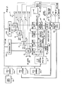
- Relays 35, 41 and 42 are operated by drivers 58 which are activated by microprocessor 21 in accordance with control signals sent through I/O expanders 24a and 24b (Fig. 2).
- These relays in combination with the three sensing circuits hook detect circuit 31, ring detect circuit 32, and DTMF receiver 33, which send status information to the microprocessor, permit the MCU to perform the functions listed below.
- DTMF transmitter 44 (which may be a key telephone), and the key pad operating it, can serve to address commands to the MCU to perform certain functions which have been programmed into its program memory. Furthermore, the digital content of each call made (such as number dialed) can be intercepted and stored in the data memory of the MCU.
- High frequency signals transmitted from microprocessor 21 to an SCU pass through time decoder 64 (such as National Semiconductor 567 phase-locked loop) after amplification by operational-amplifier 66, which utilize resistors 80, 81.
- time decoder 64 such as National Semiconductor 567 phase-locked loop
- operational-amplifier 66 which utilize resistors 80, 81.
- This arrangement results in automatically addressing the MCU by a station going off-hook using a unique address code which the MCU decodes to identify the originating station.
- This information is useful in many situations in which the MCU has to respond to a request specific of a particular station, e.g., a request to get a call back from the MCU when a redialed number is answered.
- the MCU itself dials the requested number on a CO line.
- the MCU detects a connection (answer)
- a similar pattern of modulated oscillations is sent back on the same comnunication link, but this time, the coded signals that identify the requesting station are sent from the tip and ring wires toward the SCU.
- Such coded signals are amplified on amplifier 66 and decoded by the requesting station by decoder 64. All of the other SCU's receive the coded signals, but only the requesting station will identify such signals.
- the MCU is programmed via microprocessor 59 to send back various sequences of high frequency "1" and "0" bits; and each SCU is programmed to respond to one and only one sequence.
- Piezoceramic buzzer 68 in the SCU is activated when the SCU decodes its own address alerting the user to a call initiated by the MCU.
- the digital communication between the SCU and the MCU can be used for other types of messages, for information transmission, and for activating visual indicators on the SCU side.
- the flexibility of using software on both microprocessors 21 and 59 permits other functions related to communication management of an electromechanical key system to be carried out utilizing the structure and principles of the enhancement devices described in this invention.
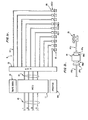
- Figs. 6 and 7 Important aspects of the invention are summarized in Figs. 6 and 7 to which reference is now made.
- station A is active because its hook switch has been closed, and because key 7 of line- select keys 6 has been actuated (depressed).
- key 7 is operatively associated with outside CO line 10-1 of CO lines 10
- actuation of key 7 will cause KSU 13 to connect tip wire 8 in cable 14A, which is coupled to SCU 16A operatively associated with station A, to tip wire 12-1 or inside CO lines 12.
- MCU 11 is operative, only fault relay 42 of the three relays, 35, 41 and 42 (Fig. 3) will be energized, and contacts 42b will be closed.
- LCU 34-1 establishes a communication link that effects addressing of SCU 16A (and any other SCU associated with a station that is active and which has selected line 10-1) by the central control which includes microprocessor 21, and addressing of the central control by SCU 16A.
- addressing information is transmitted between the central control and the various SCU's using modulated signals whose frequencies are above the audible range.
- voice information transferred via wire 12-1 between two active stations operating in an intercom mode can take place simultaneously with addressing information flowing in line 12-1 between the central control and a third SCU that becomes active.
- the address sent by SCU 16A identifies station A as being active.
- DTMF signals generated by the user at station A are transferred via link 53-1 only into the central control because LCU 34-1 is still in state I.
- Such signals are analyzed by the central control, and appropriate responses programmed into the memory of the central control are issued.
- audio information may be sent to the active station from speech ROM 48 or from tape circuit 49.
- the central control may issue a command through I/O expander 24b to change the state of LCU 34-1 by maintaining the energization of relay 42 and energizing relay 41 which closes contacts 41a coupling station A to outside line 10-1 through audio transformer 43.
- LCU 34-1 will be in state II (see Fig. 7) wherein link 53-1 will be connected directly to line 12-1 to effect the transfer of high frequency addressing information, and indirectly to line 10-1 through audio transformer 43 for effecting the transfer of audio information from the central control to both station A and to the outside line.
- relay 42 In the event of a power failure, relay 42 will be de-energized and contacts 42b and 42c will be closed; relay 41 will also be de-energized and contacts 41a will be closed. Under this condition, LCU 34-1 will be in state III; and station A will be connected via line 12-1 to line 10-1 through the audio transformer 43.
- a second embodiment of an SCU described below provides for improved signalling and communication between the MCU and various telephone sets of a system. To better appreciate the improved results achieved by the second embodiment of the SCU, a brief review of a conventional telephone system is provided.
- each telephone set is equipped with a number of push button keys respectively associated with a plurality of outside lines and constructed so that depression of a given key seizes the outside line associated with the given key. Keys on different sets associated with the same line are at equipotential.
- Each key includes a transparent cap covering a lamp that is illuminated for indicating various signals associated with the key system operation. For example, when a user wishes to engage a particular line, he depresses the push button key associated with such line; and as a consequence, the lamps in all of telephone sets associated with the particular line are simultaneously illuminated and remain in this state as long as the push button associated with the particular line remains depressed (and the line is engaged). Thus, all users are signalled that the particular line is engaged.
- the lamps at all of the telephone sets in the push button key associated with the line on which the call is coming flash simultaneously at a predetermined rate. This signals to all users that a call is coming in on that line.
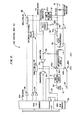
- Each line-card includes normally-open relay 105 which is activated upon depression of the particular key in each of the telephone sets associated with the CO line connected to the line-card.
- the arrangement is such that depressing the particular key in a telephone set associated with the CO line closes switch 109 within the telephone set causing the switch to connect wire 106 (commonly referred to as "A", and numbered by the CO line number lA, 2A etc.) to ground wire 107 connected to the system ground (“AG" wire).
- the resultant activation of relay 105 connects the voltage from lamp power supply 104 (typically 10 VAC) to all lamps 108 in each telephone set associated with the particular line.
- lamp power supply 104 typically 10 VAC
- All such lamps are connected across lamp wire 110, which is controlled by the relay and common to all lamps associated with same the line, and common lamp supply ground wire 111.
- the same wiring method is replicated for each line other than those shown in Fig. 8, each line being associated with its own particular keys and lamps in the telephone sets and wired in an identical way.
- Ring detect circuit 112 on line card 103 senses the high voltage caused by a ring, and operates interruptor circuit 113 which in turn intermittently activates relay 105. In this way, the lamps associated with the line having an incoming call are flashed intermittently.
- LA2 key systems Key systems like that just described, or their equivalents, are very common in the United States and elsewhere in the world, and their parts or components are standard and interchangeable irrespective of the manufacturer (AT&T, GTE, ITT etc.). Such systems are commonly termed "lA2 key systems".
- a basic condition of operation in conventional electromechanical key systems is that all lamps in the various telephone sets associated with the same CO telephone line are operated simultaneously. In the conventional key system, then, a lamp in one telephone set associated with a particular line always operates when other lamps in other sets associated with the same line are operated; and the pattern of illuminated lamps in each telephone set at any time will be the same.
- a number of advantages flow from the ability to turn lamps on and off under program control.
- the user can be signalled not only by operation of buzzer 68 of an SCU, but also by operation of lamps 108 on the telephone set.
- the illumination or blanking of these lamps indicates to the user the various MCU functions and LCU states as described previously.
- the independent nature of the control of the lamps permits a lamp associated with a particular line in one telephone to have a pattern of illumination different from other lamps in other telephone sets associated with the same line.
- the lamps can be used to convey different information to different users.
- the SCU's are effective to create distinctive indications at each or all of the various telephone sets.
- the SCU's can establish patterns of illuminated lamps in the telephone sets which differ from set to set. Consequently, lamps in the various telephone sets associated with the same CO line may have different levels of illumination permitting distinctive visual indications at each telephone set at the same time.
- the SCU's can alter the rate of change of bright and dim periods of the lamps as well as the levels of brightness. In this way, a user can be alerted to the various states of the LCU as well as various functions of the MCU such as:
- Each of the MCU functions can be indicated by a plurality of audible indications, thus permitting a number of permutations and combinations of audio visual signalling for purpose of alerting quickly and clearly the user to the system functions.
Landscapes
- Engineering & Computer Science (AREA)
- Signal Processing (AREA)
- Sub-Exchange Stations And Push- Button Telephones (AREA)
Applications Claiming Priority (2)
| Application Number | Priority Date | Filing Date | Title |
|---|---|---|---|
| US572514 | 1984-01-20 | ||
| US06/572,514 US4607144A (en) | 1984-01-20 | 1984-01-20 | Apparatus for enhancing the use of electromechanical key telephone systems |
Publications (1)
| Publication Number | Publication Date |
|---|---|
| EP0150109A2 true EP0150109A2 (de) | 1985-07-31 |
Family
ID=24288153
Family Applications (1)
| Application Number | Title | Priority Date | Filing Date |
|---|---|---|---|
| EP85300335A Withdrawn EP0150109A2 (de) | 1984-01-20 | 1985-01-17 | Gerät zur Erweiterung der Benutzung von elektromechanischen Tastengegensprechanlagen |
Country Status (5)
| Country | Link |
|---|---|
| US (1) | US4607144A (de) |
| EP (1) | EP0150109A2 (de) |
| JP (1) | JPS60180297A (de) |
| AU (1) | AU3795285A (de) |
| ZA (1) | ZA85386B (de) |
Families Citing this family (23)
| Publication number | Priority date | Publication date | Assignee | Title |
|---|---|---|---|---|
| JPS60162364A (ja) * | 1984-02-03 | 1985-08-24 | Nippo Tsushin Kogyo Kk | 音声による操作案内機能を有する通信システム |
| US6201950B1 (en) | 1984-09-14 | 2001-03-13 | Aspect Telecommunications Corporation | Computer-controlled paging and telephone communication system and method |
| US5588037A (en) * | 1984-09-14 | 1996-12-24 | Accessline Technologies, Inc. | Remote access telephone control system |
| US5375161A (en) | 1984-09-14 | 1994-12-20 | Accessline Technologies, Inc. | Telephone control system with branch routing |
| US5752191A (en) | 1984-09-14 | 1998-05-12 | Accessline Technologies, Inc. | Telephone control system which connects a caller with a subscriber AT A telephone address |
| US6545589B1 (en) | 1984-09-14 | 2003-04-08 | Aspect Communications Corporation | Method and apparatus for managing telecommunications |
| US4791662A (en) * | 1987-07-23 | 1988-12-13 | American Telephone And Telegraph Company, At&T Bell Laboratories | Controlling key-system groups from a distributed control switching system |
| US5572572A (en) * | 1988-05-05 | 1996-11-05 | Transaction Technology, Inc. | Computer and telephone apparatus with user friendly interface and enhanced integrity features |
| US5195130A (en) * | 1988-05-05 | 1993-03-16 | Transaction Technology, Inc. | Computer and telephone apparatus with user friendly computer interface and enhanced integrity features |
| US5485370A (en) * | 1988-05-05 | 1996-01-16 | Transaction Technology, Inc. | Home services delivery system with intelligent terminal emulator |
| US4885745A (en) * | 1988-10-19 | 1989-12-05 | General Datacomm, Inc. | Algorithm for minimizing excursion in placement of channel selects into multiplexer frame |
| CA1320290C (en) * | 1988-10-19 | 1993-07-13 | Kuldip Singh Bains | Algorithms for minimizing excursion in placement of channel selects into multiplexer frame |
| US4888770A (en) * | 1988-10-19 | 1989-12-19 | General Datacomm, Inc. | Algorithm for selecting channels for multiplexer frame |
| US5870724A (en) | 1989-12-08 | 1999-02-09 | Online Resources & Communications Corporation | Targeting advertising in a home retail banking delivery service |
| US5159626A (en) * | 1990-07-10 | 1992-10-27 | Execudyne Ltd. | Multi-line telephone switching system |
| JPH06225354A (ja) * | 1993-01-25 | 1994-08-12 | Toshiba Corp | ボタン電話装置 |
| US6026156A (en) * | 1994-03-18 | 2000-02-15 | Aspect Telecommunications Corporation | Enhanced call waiting |
| US5727055A (en) * | 1995-05-17 | 1998-03-10 | Ies Technologies, Inc. | Information communication systems |
| US6411682B1 (en) | 1995-09-21 | 2002-06-25 | Aspect Telecommunications Corporation | Computer controlled paging and telephone communication system and method |
| US5796832A (en) | 1995-11-13 | 1998-08-18 | Transaction Technology, Inc. | Wireless transaction and information system |
| US7162730B1 (en) | 1998-01-07 | 2007-01-09 | Honeywell International, Inc. | Information communication systems |
| US20050129219A1 (en) * | 2003-12-12 | 2005-06-16 | Robert Williamson | Method and apparatus for dialing from a directory for a communication terminal |
| US10650621B1 (en) | 2016-09-13 | 2020-05-12 | Iocurrents, Inc. | Interfacing with a vehicular controller area network |
Family Cites Families (8)
| Publication number | Priority date | Publication date | Assignee | Title |
|---|---|---|---|---|
| US29884A (en) * | 1860-09-04 | Improvement in sap-conductors | ||
| USRE29884E (en) | 1974-10-05 | 1979-01-16 | Oki Electric Industry Company, Ltd. | Key telephone system for subscribers |
| US4112261A (en) * | 1977-05-16 | 1978-09-05 | The Anaconda Company | Key telephone system and method |
| JPS54162714U (de) * | 1978-05-02 | 1979-11-14 | ||
| JPS6022868B2 (ja) * | 1979-07-03 | 1985-06-04 | 株式会社田村電機製作所 | ボタン電話交換システム |
| US4363936A (en) * | 1980-02-11 | 1982-12-14 | Stromberg-Carlson Corporation | Telephone network including common equipment with message information and control information circuits for connecting to stations having multifunction telephones |
| CA1146245A (en) * | 1980-05-16 | 1983-05-10 | Patrick R. Beirne | Keyless and indicatorless local telephone switching system |
| US4339633A (en) * | 1980-10-06 | 1982-07-13 | International Standard Electric Corporation | Modular telecommunications system |
-
1984
- 1984-01-20 US US06/572,514 patent/US4607144A/en not_active Expired - Fee Related
-
1985
- 1985-01-17 ZA ZA85386A patent/ZA85386B/xx unknown
- 1985-01-17 EP EP85300335A patent/EP0150109A2/de not_active Withdrawn
- 1985-01-21 JP JP60009805A patent/JPS60180297A/ja active Pending
- 1985-01-21 AU AU37952/85A patent/AU3795285A/en not_active Abandoned
Also Published As
| Publication number | Publication date |
|---|---|
| US4607144A (en) | 1986-08-19 |
| AU3795285A (en) | 1985-08-01 |
| ZA85386B (en) | 1985-08-28 |
| JPS60180297A (ja) | 1985-09-14 |
Similar Documents
| Publication | Publication Date | Title |
|---|---|---|
| EP0150109A2 (de) | Gerät zur Erweiterung der Benutzung von elektromechanischen Tastengegensprechanlagen | |
| US4451705A (en) | Call completion circuit and method | |
| US4850012A (en) | Automated access facilities for use with key telephone systems | |
| US5048076A (en) | Control apparatus for an automated telephone attendant | |
| US5550900A (en) | Apparatus and method for routing messages in a telephone message center | |
| US4922526A (en) | Automated access facilities for use with key telephone systems | |
| US5022069A (en) | Modular automatic telephone switching system | |
| US5086458A (en) | Telephone answering system and apparatus for direct caller selection of a party line extension | |
| US4291199A (en) | Communication system tracking arrangement | |
| JPH0566780B2 (de) | ||
| WO1989003622A1 (en) | Direct access test unit for central office | |
| JPH01213094A (ja) | キーテレホンシステム | |
| JPS6410150B2 (de) | ||
| CA2035716C (en) | Private branch exchange system | |
| US3665112A (en) | Multi-line telephone set with switching capability | |
| EP0515241B1 (de) | Fernsprechkonferenzsystem | |
| JP2721367B2 (ja) | 電話装置 | |
| US4536615A (en) | Key telephone equipment and associated method | |
| JPH11513854A (ja) | 遠隔通信スイッチ | |
| JPH0147067B2 (de) | ||
| EP0018844B1 (de) | Fernsprechsysteme | |
| US5005199A (en) | Telephone interface circuit | |
| EP0176291A2 (de) | Tastengegensprechanlage mit verteilter Steuerung | |
| US3299217A (en) | Auxiliary interconnecting unit for multi-line subscriber telephone system | |
| GB2243518A (en) | "pbx" |
Legal Events
| Date | Code | Title | Description |
|---|---|---|---|
| PUAI | Public reference made under article 153(3) epc to a published international application that has entered the european phase |
Free format text: ORIGINAL CODE: 0009012 |
|
| AK | Designated contracting states |
Designated state(s): DE FR GB IT |
|
| STAA | Information on the status of an ep patent application or granted ep patent |
Free format text: STATUS: THE APPLICATION IS DEEMED TO BE WITHDRAWN |
|
| 18D | Application deemed to be withdrawn |
Effective date: 19870804 |
|
| RIN1 | Information on inventor provided before grant (corrected) |
Inventor name: SONESH, ARIE Inventor name: CARMON, AMIRAM |