EP0150120A2 - Système de vidange pour appareil de traitement de carburant - Google Patents
Système de vidange pour appareil de traitement de carburant Download PDFInfo
- Publication number
- EP0150120A2 EP0150120A2 EP85300377A EP85300377A EP0150120A2 EP 0150120 A2 EP0150120 A2 EP 0150120A2 EP 85300377 A EP85300377 A EP 85300377A EP 85300377 A EP85300377 A EP 85300377A EP 0150120 A2 EP0150120 A2 EP 0150120A2
- Authority
- EP
- European Patent Office
- Prior art keywords
- chamber
- fuel
- water
- fuel processor
- impurities
- Prior art date
- Legal status (The legal status is an assumption and is not a legal conclusion. Google has not performed a legal analysis and makes no representation as to the accuracy of the status listed.)
- Ceased
Links
Images


Classifications
-
- F—MECHANICAL ENGINEERING; LIGHTING; HEATING; WEAPONS; BLASTING
- F02—COMBUSTION ENGINES; HOT-GAS OR COMBUSTION-PRODUCT ENGINE PLANTS
- F02D—CONTROLLING COMBUSTION ENGINES
- F02D33/00—Controlling delivery of fuel or combustion-air, not otherwise provided for
- F02D33/003—Controlling the feeding of liquid fuel from storage containers to carburettors or fuel-injection apparatus ; Failure or leakage prevention; Diagnosis or detection of failure; Arrangement of sensors in the fuel system; Electric wiring; Electrostatic discharge
-
- B—PERFORMING OPERATIONS; TRANSPORTING
- B01—PHYSICAL OR CHEMICAL PROCESSES OR APPARATUS IN GENERAL
- B01D—SEPARATION
- B01D17/00—Separation of liquids, not provided for elsewhere, e.g. by thermal diffusion
-
- B—PERFORMING OPERATIONS; TRANSPORTING
- B01—PHYSICAL OR CHEMICAL PROCESSES OR APPARATUS IN GENERAL
- B01D—SEPARATION
- B01D17/00—Separation of liquids, not provided for elsewhere, e.g. by thermal diffusion
- B01D17/02—Separation of non-miscible liquids
- B01D17/0208—Separation of non-miscible liquids by sedimentation
- B01D17/0214—Separation of non-miscible liquids by sedimentation with removal of one of the phases
-
- B—PERFORMING OPERATIONS; TRANSPORTING
- B01—PHYSICAL OR CHEMICAL PROCESSES OR APPARATUS IN GENERAL
- B01D—SEPARATION
- B01D17/00—Separation of liquids, not provided for elsewhere, e.g. by thermal diffusion
- B01D17/08—Thickening liquid suspensions by filtration
- B01D17/10—Thickening liquid suspensions by filtration with stationary filtering elements
-
- B—PERFORMING OPERATIONS; TRANSPORTING
- B01—PHYSICAL OR CHEMICAL PROCESSES OR APPARATUS IN GENERAL
- B01D—SEPARATION
- B01D17/00—Separation of liquids, not provided for elsewhere, e.g. by thermal diffusion
- B01D17/12—Auxiliary equipment particularly adapted for use with liquid-separating apparatus, e.g. control circuits
-
- B—PERFORMING OPERATIONS; TRANSPORTING
- B01—PHYSICAL OR CHEMICAL PROCESSES OR APPARATUS IN GENERAL
- B01D—SEPARATION
- B01D36/00—Filter circuits or combinations of filters with other separating devices
- B01D36/003—Filters in combination with devices for the removal of liquids
-
- C—CHEMISTRY; METALLURGY
- C10—PETROLEUM, GAS OR COKE INDUSTRIES; TECHNICAL GASES CONTAINING CARBON MONOXIDE; FUELS; LUBRICANTS; PEAT
- C10G—CRACKING HYDROCARBON OILS; PRODUCTION OF LIQUID HYDROCARBON MIXTURES, e.g. BY DESTRUCTIVE HYDROGENATION, OLIGOMERISATION, POLYMERISATION; RECOVERY OF HYDROCARBON OILS FROM OIL-SHALE, OIL-SAND, OR GASES; REFINING MIXTURES MAINLY CONSISTING OF HYDROCARBONS; REFORMING OF NAPHTHA; MINERAL WAXES
- C10G33/00—Dewatering or demulsification of hydrocarbon oils
- C10G33/06—Dewatering or demulsification of hydrocarbon oils with mechanical means, e.g. by filtration
-
- F—MECHANICAL ENGINEERING; LIGHTING; HEATING; WEAPONS; BLASTING
- F02—COMBUSTION ENGINES; HOT-GAS OR COMBUSTION-PRODUCT ENGINE PLANTS
- F02M—SUPPLYING COMBUSTION ENGINES IN GENERAL WITH COMBUSTIBLE MIXTURES OR CONSTITUENTS THEREOF
- F02M31/00—Apparatus for thermally treating combustion-air, fuel, or fuel-air mixture
- F02M31/02—Apparatus for thermally treating combustion-air, fuel, or fuel-air mixture for heating
- F02M31/12—Apparatus for thermally treating combustion-air, fuel, or fuel-air mixture for heating electrically
- F02M31/125—Fuel
-
- F—MECHANICAL ENGINEERING; LIGHTING; HEATING; WEAPONS; BLASTING
- F02—COMBUSTION ENGINES; HOT-GAS OR COMBUSTION-PRODUCT ENGINE PLANTS
- F02M—SUPPLYING COMBUSTION ENGINES IN GENERAL WITH COMBUSTIBLE MIXTURES OR CONSTITUENTS THEREOF
- F02M37/00—Apparatus or systems for feeding liquid fuel from storage containers to carburettors or fuel-injection apparatus; Arrangements for purifying liquid fuel specially adapted for, or arranged on, internal-combustion engines
- F02M37/0047—Layout or arrangement of systems for feeding fuel
-
- F—MECHANICAL ENGINEERING; LIGHTING; HEATING; WEAPONS; BLASTING
- F02—COMBUSTION ENGINES; HOT-GAS OR COMBUSTION-PRODUCT ENGINE PLANTS
- F02M—SUPPLYING COMBUSTION ENGINES IN GENERAL WITH COMBUSTIBLE MIXTURES OR CONSTITUENTS THEREOF
- F02M37/00—Apparatus or systems for feeding liquid fuel from storage containers to carburettors or fuel-injection apparatus; Arrangements for purifying liquid fuel specially adapted for, or arranged on, internal-combustion engines
- F02M37/22—Arrangements for purifying liquid fuel specially adapted for, or arranged on, internal-combustion engines, e.g. arrangements in the feeding system
- F02M37/24—Arrangements for purifying liquid fuel specially adapted for, or arranged on, internal-combustion engines, e.g. arrangements in the feeding system characterised by water separating means
- F02M37/26—Arrangements for purifying liquid fuel specially adapted for, or arranged on, internal-combustion engines, e.g. arrangements in the feeding system characterised by water separating means with water detection means
- F02M37/28—Arrangements for purifying liquid fuel specially adapted for, or arranged on, internal-combustion engines, e.g. arrangements in the feeding system characterised by water separating means with water detection means with means activated by the presence of water, e.g. alarms or means for automatic drainage
-
- F—MECHANICAL ENGINEERING; LIGHTING; HEATING; WEAPONS; BLASTING
- F02—COMBUSTION ENGINES; HOT-GAS OR COMBUSTION-PRODUCT ENGINE PLANTS
- F02M—SUPPLYING COMBUSTION ENGINES IN GENERAL WITH COMBUSTIBLE MIXTURES OR CONSTITUENTS THEREOF
- F02M37/00—Apparatus or systems for feeding liquid fuel from storage containers to carburettors or fuel-injection apparatus; Arrangements for purifying liquid fuel specially adapted for, or arranged on, internal-combustion engines
- F02M37/22—Arrangements for purifying liquid fuel specially adapted for, or arranged on, internal-combustion engines, e.g. arrangements in the feeding system
- F02M37/30—Arrangements for purifying liquid fuel specially adapted for, or arranged on, internal-combustion engines, e.g. arrangements in the feeding system characterised by heating means
-
- F—MECHANICAL ENGINEERING; LIGHTING; HEATING; WEAPONS; BLASTING
- F02—COMBUSTION ENGINES; HOT-GAS OR COMBUSTION-PRODUCT ENGINE PLANTS
- F02M—SUPPLYING COMBUSTION ENGINES IN GENERAL WITH COMBUSTIBLE MIXTURES OR CONSTITUENTS THEREOF
- F02M37/00—Apparatus or systems for feeding liquid fuel from storage containers to carburettors or fuel-injection apparatus; Arrangements for purifying liquid fuel specially adapted for, or arranged on, internal-combustion engines
- F02M37/22—Arrangements for purifying liquid fuel specially adapted for, or arranged on, internal-combustion engines, e.g. arrangements in the feeding system
- F02M37/32—Arrangements for purifying liquid fuel specially adapted for, or arranged on, internal-combustion engines, e.g. arrangements in the feeding system characterised by filters or filter arrangements
-
- F—MECHANICAL ENGINEERING; LIGHTING; HEATING; WEAPONS; BLASTING
- F02—COMBUSTION ENGINES; HOT-GAS OR COMBUSTION-PRODUCT ENGINE PLANTS
- F02B—INTERNAL-COMBUSTION PISTON ENGINES; COMBUSTION ENGINES IN GENERAL
- F02B3/00—Engines characterised by air compression and subsequent fuel addition
- F02B3/06—Engines characterised by air compression and subsequent fuel addition with compression ignition
-
- Y—GENERAL TAGGING OF NEW TECHNOLOGICAL DEVELOPMENTS; GENERAL TAGGING OF CROSS-SECTIONAL TECHNOLOGIES SPANNING OVER SEVERAL SECTIONS OF THE IPC; TECHNICAL SUBJECTS COVERED BY FORMER USPC CROSS-REFERENCE ART COLLECTIONS [XRACs] AND DIGESTS
- Y02—TECHNOLOGIES OR APPLICATIONS FOR MITIGATION OR ADAPTATION AGAINST CLIMATE CHANGE
- Y02T—CLIMATE CHANGE MITIGATION TECHNOLOGIES RELATED TO TRANSPORTATION
- Y02T10/00—Road transport of goods or passengers
- Y02T10/10—Internal combustion engine [ICE] based vehicles
- Y02T10/12—Improving ICE efficiencies
Definitions
- the invention relates generally to automatic drain systems and more particularly to such drain systems for fuel processing apparatus for diesel and other types of engines.
- one important object of this invention is to provide a new and improved fuel processor apparatus particularly for diesel trucks and other diesel-powered automotive vehicles to remove water and other impurities from the diesel fuel and to provide improved means for draining the water or other impurities from the processor apparatus.
- An improved fuel processor apparatus broadly includes a fluid-tight chamber or canister through which the fuel flows and in which water and other inpurities are separated in a lower portion of the chamber or cannister.
- a sensing apparatus is located in the lower portion of the chamber for detecting the presence of a predetermined quantity of water or other impurities, and a drain device is actuable, either manually or preferably automatically, in response to detection of said predetermined quantity to discharge at least a substantial portion of the water or other impurities in order to maintain them at or below said predetermined quantity.
- automatic control means is provided for automatically actuating the drain device in response to detection of said predetermined quantity and for automatically deactuating the drain device in response to detection of a second lower quantity of such water or other impurities.
- the quantity of water or other impurities is maintained generally between said predetermined and second quantities in order to substantially ensure that fuel is not discharged when the drain device is actuated.
- This invention contemplates fuel processing systems which are located within an engine supply circuit and further systems which are employed to draw fuel from a tank and recirculate it to the tank after processing.
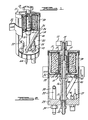
- Figures 1 through 5 of the drawings illustrate exemplary embodiments of the present invention as incorporated into a diesel fuel processing apparatus having an electric heating element and an integral filter section with a filter cartridge therein.
- One skilled in the art will readily recognize from the following discussion that the principles of the invention are equally applicable to other types of fluid separator devices as well as to other types of fuel processing apparatus other than that shown in the drawings, including the fuel processing devices disclosed in U.S. Patent No. 4,368,716, issued January 18, 1983, and copending application, serial no. 287,149, filed July 27, 1981, both of which are assigned to the same assignee as the assignee herein.
- the disclosures of said patent and said copending application are incorporated by reference herein.
- the embodiments shown by Figures 1 through 5 are most preferably enplcyed within the fuel supply circuit of the motor vehicle engine. In this manner, fuel is treated as it is drawn by the engine fuel supply system.
- Reference character 10 designates generally a fluid-tight open-topped cylindrical enclosure or chamber to which a gasketed fluid-tight cover 11 is removably and clampingly secured by means of a wing nut 12.
- a two-part tubular support and conduit assembly designated generally at 15 is positioned axially in the chamber 10 and has a bottom section 16 rigidly and threadably secured in, and upstanding from, a suitably tapped opening 17 in the bottom wall 23 of the chamber 10.
- the support and conduit assembly 15 has an upper section 18 rigidly and threadably attached to the lower section 16.
- the interiors of the tubular sections 16 and 18 communicate to define an axial passage 20 which communicates with the exterior of the chamber 10 through a fitting 22 to which a fuel outlet conduit (not shown) is adapted to be sealingly attached.
- the threadably interfitted male and female portions 24 and 24a, respectively, of the upper and lower sections 18 and 16 serve as means for rigidly supporting a combined baffle and filter supporting plate 25 clamped therebetween.
- Supporting plate 25 is of a diameter slightly less than the inside diameter of the canister or chamber, thereby providing a relatively narrow annular slot 26 for a purpose described below.
- the upper end of the tubular section 18 is tapped to threadably receive a stud 14 for attachment to the wing nut 12 and to provide a firm support for attachment of the cover 11.
- a fuel inlet fitting 30 attached to, and extending through the bottom wall 23 of the chamber 10 is adapted to deliver fuel to the lower chamber portion 32 below the supporting plate 25.
- An inlet pipe 33 connected to the fitting 30 extends upwardly within the chamber 32 and has an outlet generally tangential to the inside wall of the chamber to impart a rotary motion to the fuel therein.
- the fuel flows upwardly from the lower chamber portion 32 through the gap or slot 26 into the upper chamber portion 35 above the supporting plate 25. After passing inwardly through a filter element 50, the fuel enters the upper passage portion 21 in the upper support tube section 18, by way of radially-extending holes 36, and is then conveyed downwardly through passage 20, out through the fuel discharge fitting 22, and to the fuel inlet of the engine.
- An electric heating element 40 is provided in the lower chamber portion 32 and is bent to an inverted U-shaped form, having its lower ends in communication with electrical connections 42 and 44 being supported in the bottom wall 23 of the chamber. It should be noted that the upper end of the heating element 40 extends to a position close to the gap 26 through which the fuel flows to the upper chamber portion 35, which contains the filter 50. If a different type of heating unit is employed, such as the fluid-conveying tubular heater shown in the above-mentioned U.S. Patent No. 4,368,716 and in the oopending application, serial no. 287,419, it also projects upwardly from the bottom wall to a position close to the gap 26 so that its upper portion is positioned comparably to the bight portion 41 of the heating element 40. Such a heater, as well as other types of beaters known in the art, may be substituted for the heating element 40 shown in the drawings herein for purposes of illustration.
- the bight portion 41 of the heater element 40 is slightly spaced from both the supportable plate 25 and the inner wall of the chamber 10.
- the heating element is also energized and warmed very quickly, and consequently the fuel close to the heating element is also warmed very quickly. This is important in cold weather, because wax crystals which have formed in the cold fuel tend to readily clog the filter element 50.
- the heating element 40 When the heating element 40 is initially energized, there is insufficient heat build-up to heat all of the fuel adequately to melt wax or ice crystals, but only a small amount of heat is needed to melt such cyrstals in a small region of the gap 26 and the lower edge of the side of the filter 50 that is adjacent the bight portion 41 of the heating element.
- the portion of the fuel flowing through the gap 26 at a position close to the bight portion 41 of the heating element is sufficiently heated quickly enough to maintain a clear, wax-free path or "window" through the filter 50 until the fuel processing apparatus, and the engine itself, can reach normal, steady state operating temperatures.
- the fuel in the entire lower chamber portion 32 When the fuel in the entire lower chamber portion 32 is warmed, it of course freely flows upwardly through the entire annular gap.
- the bottom wall 23 of the chamber 10 also supports a drain valve means, indicated generally by reference numeral 45, for discharging water and other impurities that have been separated out into the lower chamber portion 32.
- the drain valve means 45 is an electric solenoid-operated valve, as shown in the drawings, but may alternately be operated manually or by pneumatic, hydraulic, or other means known to those skilled in the art.
- a chamber quantity sensing means, indicated generally ty reference numeral 55, is also provided for detecting the presence of various quantities of water or other impurities in the lower chamber portion 32 and for generating a signal in response thereto.
- the fuel processing apparatus may also optionally, if desired, include a chamber temperature sensing means 48 for detecting and monitoring the temperature of the water or other fluids or impurities in the lower chamber portion 32 and for generating a signal in response to detection of said temperatures below a predetermined value.
- a chamber temperature sensing means 48 for detecting and monitoring the temperature of the water or other fluids or impurities in the lower chamber portion 32 and for generating a signal in response to detection of said temperatures below a predetermined value.
- the filter element or cartridge 50 may be of a known commercially-available cylindrical drop-in type, supported and clamped between the cover and the supporting plate 25 on suitable hub portions 13 and 19 projecting from the cover and from the upper tube section 18, respectively, with suitable gasketing means being provided as indicated at 51 and 52.
- suitable gasketing means being provided as indicated at 51 and 52.
- other filters of the drop-in, internal, or spin-on types as disclosed in the above-mentioned U.S. Patent No. 4,368,716 and in the copending application, serial no. 287,419, for example, may be employed.
- the fuel processing unit is adapted to be mounted in a suitable location by means of a bracket 56 at a position where the upper portion is readily accessible so that when desired the cover 11 may be removed and the filter element 50 replaced.
- FIGS 3 through 5 schematically illustrate several exemplary variations of the preferred form of the present invention.
- the lower portion 32 of the chanber 10 which is under a positive pressure, includes a chamber quantity sensing means and a drain valve means.
- the sensing means preferably comprises a chamber fluid level sensor 60 having an electrical probe 62, a lower portion of which is surrounded by insulating means 64, extending generally upwardly therein.
- the drain valve means preferably comprises a solenoid-operated valve 70 located at the bottan of the chamber and having at least one inlet 72 and an outlet 74, which are configured such that the valve 70 provides fluid communication between the interior of the lower chamber portion 32 and the exterior of the chamber 10 when actuated and prevents such fluid communication when deactuated.
- the chamber fluid level sensor 60 is adapted to generate distinct signals when the electrical probe 62 is exposed at various points along its vertical length or height to one or more fluids having distinct electrical characteristics, such as electrical conductivity or resistance, for example.
- the sensor 60 is connected by way of an electrical conductor 61 to an automatic controller 80, and similarly the solenoid-operated valve 70 is connected by way of electrical conductor 63 to the controller 80.
- water and/or other inpurities are separated from the fuel and settle to the bottom of the lower chamber portion 32, thereby creating an interface between the fuel and the water and/or other impurities. Since the fuel and such water and/or impurities typically have different electrical characteristics, the signal generated by the probe 62 changes as the level of such interface moves up and down its vertical length or height.
- Such signal therefore changes as greater quantities of water and/or other impurities are separated from the fuel in the lower chamber portion 32, ranging fran a condition wherein the interface is at a level below the upper end of the insulating means 64 and the probe 62 is exposed only to fuel, to a condition wherein the interface has risen to various intermediate positions on the probe 62 so that the probe is exposed to varying amounts of fuel and water and/or other inpurities, and finally to a condition wherein the interface is at or above the upper end of the probe and the probe is exposed only to water/impurities.
- the controller 80 which preferably comprises a conventional microprocessor unit or other electronic circuitry known to those skilled in the art, is adapted to receive, and differentiate between, the varying signals from the sensor 60 as the level of the above-mentioned interface changes.
- the controller 80 is pre-set, adapted, or programmed to cause the solenoid-operated valve 70 to be actuated at a predetermined high level of such interface between the fuel and the water and/or other impurities, such as at the level 90.
- the controller 80 is also pre-set, adapted, or programmed such that when the valve 70 is actuated, the water and/or other impurities are discharged through the outlet 74 of the valve 70 until the level of the interface recedes to a predetermined low interface level, such as the level 92, at which time the valve 70 is deactuated and closed.
- a predetermined low interface level such as the level 92
- the level 92 should be established so that the interface is above the inlet 72 of the valve 70 in order to avoid dunping or discharging fuel along with the water and/or other impurities.
- the temperature sensing means 48 may optionally be included and connected to the controller 80, such as by way of electrical conductor 65, to override and prevent the controller 80 fran causing the valve 70 to discharge the water and/or other impurities if the temperature in the lower chamber portion 32 is below a predetermined temperature level.
- a predetermined temperature level should be slightly above the freezing point of the mixture of water and other impurities in order to avoid damage to, or improper operation of, the valve 70 due to frozen solids being introduced therein.
- the heating element 40 may optionally be connected to a power source (not shown) by way of the controller 80 so that the controller may also be used to regulate the power to the heating element in response to signals from the temperature sensing means 48.
- the tenperature sensing means 48 may comprise a thermostat device, a thermistor, or other such temperature sensing devices known to those skilled in the art.
- FIG. 4 The variation of the present invention represented schematically in Figure 4 is substantially similar to that described above in connection with Figure 3, except that the exemplary single-probe chamber fluid level sensor 60 of Figure 3 is replaced by an exemplary dual-probe chamber fluid level sensor 60'.
- Chamber fluid level sensor 60' includes a pair of electrical probes 68 extending generally upwardly in the lower chamber portion 32 and located closely adjacent to one another.
- the dual-probe sensor 60' measures such electrical quantities between the two probes 68, themselves.
- the dual-probe sensor 60' is capable of more accurate measurements of the level of the interface between the fuel and the water and/or other impurities. Such increased accuracy is believed to exist especially when the fuel processor apparatus is disposed at an attitude such that the fluids therein are not substantially horizontal, such as when a vehicle having the apparatus thereon is travelling on uneven terrain or is engaged in sharp cornering maneuvers, for example.
- the chamber fluid level sensor 60' is adapted to generate distinct signals when the probes 68 are exposed to one or more fluids extending between them at various corresponding levels along their lengths.
- the sensor 60' generates a signal that changes as the level of the interface between the fuel and the water or other ispurities moves up and down at various levels on the probes 68.
- signal changes as is described above in connection with Figure 3, as greater quantities of the water and/or other impurities are separated from the fuel in the lower chamber portion 32.
- the controller 80 is pre-set,' adapted, or programmed to receive and differentiate between the varying signals from the sensor 60' in order to actuate the solenoid-operated valve 70 at a predetermined high level of the interface, such as at the level 90, and to deactuate the solenoid-operated valve at a predetermined low level, such as the level 92.
- the variation of the present invention which is represented schematically in Figure 5 is substantially similar to those shown and described above in connection with Figures 3 and 4, but is particularly adapted for use in a chamber 10 that is under a negative pressure.
- Such negative pressure at least inhibits, if not prevents, the water and/or other impurities fran being discharged under the force of gravity through the solenoid-operated valve 70, as in the positive-pressure arrangements shown schematically in Figures 3 and 4. Therefore, the solenoid-operated valve 70' in Figure 5 includes a pump means 96 incorporated therein.
- the controller 80 when the controller 80 receives a signal from the chamber fluid level sensor 60 or 60', which corresponding to an interface level at the predetermined level 90, the controller 80 causes the solenoid-operated valve 70' and the pump means 96, which is preferably a positive displacement pump, to be activated to forcibly discharge the water or other impurities from the chamber 10.
- the controller 80 causes the solenoid-operated valve 70' and the pump means 96 to be deactuated.
- the controller 80 may be pre-set, adapted, or programmed to actuate the solenoid-operated valve 70' and the punp means 96 only for a predetermined time period after the fluid level sensor senses an interface level at the predetermind high level 90.
- such predetermined timed actuation of the solenoid-operated valve 70' and the pump means 96 may be used in conjunction with the above-described actuation and deactuation in response to interface levels 90 and 92, respectively, and therefore serve as a redundant back-up feature for such normal operation.
- the arrangement shown schematically in Figure 5 may alternately include either a single-probe sensor as in Figure 3 or a multi-probe sensor as in Figure 4.
- FIG. 6 An additional embodiment of a fuel processor apparatus according to this invention is described with reference to Figures 6 and 7.
- the embodiment described by those Figures is preferably employed in connection with a fuel processor system which draws fuel from the fuel tank, circulates it through the fuel processor, and then returns it to the fuel tank.
- a fuel processor system which draws fuel from the fuel tank, circulates it through the fuel processor, and then returns it to the fuel tank.
- Such configuration does not require fuel flow to an engine or another fuel consuming device in order to treat the fuel.
- This system permits fuel in a fuel tank to be treated irrespective of operation of an engine or other fuel consuming device.
- fuel may be drawn from the tank, circulated through the fuel processor where it is heated and water is removed and then returned to the fuel tank.
- a fuel processor generally referred to by reference character 108 may include a completely enclosed cylindrical vessel 110 forming fluid inlet 112 and fluid outlet 114.
- Fluid inlet l12 is located near the vertical center of cylindrical enclosure 110 which is elongated in a vertical direction.
- Fluid outlet 114 is located at or near the vertical top of the enclosure 110.
- This configuration permits water, which has a specific gravity greater than that of the fuel contained within fuel tank 116, to settle to the bottom region of cylindrical enclosure 110, as previously described.
- Fuel processor cylindrical enclosure 110 is shown without an internal particulate filter, unlike the previously described embodiments. Since fuel circulating through processor 108 is returned to the fuel tank, and not to the engine, such a filter is unnecessary. However, it may be desired in sane applications to provide such a filter, and such modification is entirely within the scope of this invention.
- Fuel processor 108 is connected to fuel tank 116 via inlet conduit 118 and outlet conduit 120.
- inline fuel pump 122 which is preferably energized by electrical power.
- fuel is drawn from near the bottom of fuel tank 116, circulated through fuel processor 108 and returned to the fuel tank at a point some distance from the inlet conduit pickup.
- a fuel tank water sensor 124 provides a signal responsive to water accumulation within the fuel tank.
- Fuel tank 116 may also include a temperature sensing apparatus 126. As will be subsequently described, fuel tank water sensor 124 will function to energize inline fuel pump 122 when a predetermined quantity of water or other impurity is sensed within fuel tank 116. Temperature sensor 126 within fuel tank 116 may also be employed to energize inline fuel pump 122 when the fuel temperature falls below a desired level.
- Fuel processor 108 employs many of the elements previously described in connection with other embodiments of this invention.
- Cylindrical enclosure bottom 111 forms a mounting location for a solenoid operated water valve 70, having an inlet 72 and an outlet 74 acting to controllably permit the discharge of or retention of fluid within cylindrical enclosure 110.
- inline fuel pump 122 is connected to outlet conduit 120, causing a negative fluidic pressure within enclosure 110, it will be necessary to replace solenoid operated water valve 70 with a pump means 96, as previously described.
- Beating element 40 is also installed within cylindrical enclosure 110. As previously described, such a heating element may comprise an electrical resistance-type heating element or a number of other types.
- Temperature sensing means 48 is further incorporated within the cylindrical enclosure 110, and preferably located in enclosure bottom 111.
- This embodiment of the invention further features a modified system for sensing the presence of water within fluid contained by cylindrical enclosure 110.
- this embodiment features a pair of substantially flat probes 128 and 130 installed within the side surface of enclosure 110 which are both installed at an equal vertical height.
- Probes 128 and 130 like probes 62 and 68, provide a signal responsive to the differing electrical characteristics of fuel and water or impurities and are insulated electrically from enclosure 110 by insulators 148 and 150 in the event that the enclosure is formed from an electrically conductive material.
- a pair of such probes are located directly opposing one another and oriented such that they face the fore and aft directions of the associated motor vehicle.
- Such configuration permits the water sensing mechanism to compensate for the affects of vehicle acceleration and deceleration which causes the interface surface between retained water and fuel within the processor to become inclined. These effects may be compensated for by requiring that both probes 128 and 130 detect the presence of impurities before valve 70 is caused to discharge fluid. Further, the effects of transient changes in the fluid within enclosure 110 may be minimized by requiring that the probes sense the presence of impurities for at least a minimum period of time, for example five seconds.
- the means for detecting the presence of impurities within enclosure 110 including probes 128 and 130 is equally useful if used in connection with the embodiment of the invention previously described and such use is entirely within the scope of this invention.
- Probes 128 and 130 unlike the earlier described probes 62 and 68, are not capable of providing signals responsive to several predetermined quantities of water retained within enclosure 110, therefore means are provided to cause a desired quantity of fluid to be discharged from solenoid operated water valve 70 in the event that water is detected as is described below in connection with the operation of the system.
- Controller 80 preferably of integrated circuit-type, operates to perform two distinct functions when used in connection with the embodiment shown by Figures 6 and 7.
- a pair of electrical conductors 132 and 134 transmit signals between controller 80 and fuel tank water sensor 124 and fuel tank temperature sensor 126. Signals generated by these fuel tank mounted sensors are employed by the controller to selectively energize and de-energize inline fuel pump 122.
- inline fuel pump 122 is caused to energize and circulate fuel through fuel processor 108.
- Inline fuel pump 122 may also be caused to energize when tank temperature sensor 126 detects a fuel temperature below a predetermined level, and would be caused to de-energize once the fuel temperature is warmed sufficiently by fuel processor 108.
- Controller 80 also functions to monitor the conditions within fuel processor 108 to selectively cause solenoid operated water valve 70 to allow material accumulating within cylindrical enclosure 110 to be dumped or retained as desired.
- Sensors 128 and 130 are connected to controller 80 by conductors 136 and 138 respectively.
- valve 70 is connected to the controller by conductor 140.
- probes 128 and 130 are capable of detecting only one predetermined quantity of water retained within enclosure 110.
- This predetermined quantity which probes 128 and 130 respond to is a function of their vertical positioning within enclosure 110.
- This predetermined level occurs as the interface between fuel and water in the enclosure is at the position indicated by line 146 whereupon the interface reaches both sensors 128 and 130.
- valve 70 could be caused by controller 80 to open for a predetermined duration, calculated to cause the expulsion of a desired portion of the fluid existing below the level at which probes 128 and 130 are placed.
- the quantity of fluid which would be expelled over a given time duration can be estimated by opening the valve only when pump 122 is operated. In such conditions, it could be assumed that all of the fluid pumped by the pump is displacing fluid within enclosure 110 which is being dumped by valve 70. This assumption can be made since the fluid flow path of resistance is much less restrictive through valve 70 as compared with outlet conduit 120, and therefore, when the valve is opened the fluid flow through the outlet conduit becomes negligible.
- Controller 80 may also be employed to monitor the temperature of fluid within enclosure 110. By receiving a temperature signal supplied by sensor 48 via conductor 142, the electrical power provided to heater 40 through conductor 144 can be modulated. In addition, a temperature signal may be used to prevent the opening of valve 70 when ice has formed in the enclosure, thereby preventing damage to the valve.
Landscapes
- Engineering & Computer Science (AREA)
- Chemical & Material Sciences (AREA)
- Mechanical Engineering (AREA)
- Chemical Kinetics & Catalysis (AREA)
- Combustion & Propulsion (AREA)
- General Engineering & Computer Science (AREA)
- Thermal Sciences (AREA)
- Physics & Mathematics (AREA)
- Oil, Petroleum & Natural Gas (AREA)
- General Chemical & Material Sciences (AREA)
- Organic Chemistry (AREA)
- Production Of Liquid Hydrocarbon Mixture For Refining Petroleum (AREA)
- Cooling, Air Intake And Gas Exhaust, And Fuel Tank Arrangements In Propulsion Units (AREA)
- Filtration Of Liquid (AREA)
- Feeding And Controlling Fuel (AREA)
Applications Claiming Priority (2)
| Application Number | Priority Date | Filing Date | Title |
|---|---|---|---|
| US573292 | 1984-01-23 | ||
| US06/573,292 US4539109A (en) | 1983-02-01 | 1984-01-23 | Drain system for fuel processor apparatus |
Publications (2)
| Publication Number | Publication Date |
|---|---|
| EP0150120A2 true EP0150120A2 (fr) | 1985-07-31 |
| EP0150120A3 EP0150120A3 (fr) | 1985-12-04 |
Family
ID=24291392
Family Applications (1)
| Application Number | Title | Priority Date | Filing Date |
|---|---|---|---|
| EP85300377A Ceased EP0150120A3 (fr) | 1984-01-23 | 1985-01-21 | Système de vidange pour appareil de traitement de carburant |
Country Status (4)
| Country | Link |
|---|---|
| US (1) | US4539109A (fr) |
| EP (1) | EP0150120A3 (fr) |
| JP (1) | JPS60159362A (fr) |
| CA (1) | CA1245569A (fr) |
Cited By (10)
| Publication number | Priority date | Publication date | Assignee | Title |
|---|---|---|---|---|
| GB2272652A (en) * | 1992-11-20 | 1994-05-25 | Knecht Filterwerke Gmbh | A fuel filter |
| EP1081371A3 (fr) * | 1999-09-03 | 2001-10-24 | Salvatore Italiano | Dispositif pour enlever automatiquement de l'eau et de l'air des filtres à carburant |
| WO2001096731A1 (fr) * | 2000-06-12 | 2001-12-20 | Sogefi Filtration S.P.A. | Filtre de carburant diesel de moteur |
| SG115574A1 (en) * | 2002-10-21 | 2005-10-28 | Hasan Hamdan Abdelqader Ali | Diesel fuel purifier |
| US6974120B2 (en) | 2002-07-11 | 2005-12-13 | Parker Hannifin (Uk) Ltd. | Solenoid fuel drain valve |
| EP1642632A1 (fr) * | 2004-10-04 | 2006-04-05 | Mann+Hummel Gmbh | Filtre à liquide |
| DE202005015595U1 (de) * | 2005-09-30 | 2007-02-08 | Mann + Hummel Gmbh | Vorrichtung zur Wasserabführung aus einem Kraftstoffbehälter |
| DE202006019301U1 (de) * | 2006-12-23 | 2008-04-30 | Mann+Hummel Gmbh | Kraftstofffilter |
| EP1567762B2 (fr) † | 2002-12-03 | 2011-11-09 | UFI Filters S.p.A. | Filtre de carburant pour moteur diesel a injection directe sous haute pression du type de systeme a galerie commune et analogue |
| DK201670613A1 (en) * | 2016-08-11 | 2018-02-26 | Maersk As | A fuel system for a marine engine |
Families Citing this family (24)
| Publication number | Priority date | Publication date | Assignee | Title |
|---|---|---|---|---|
| AU2906189A (en) * | 1987-12-18 | 1989-07-19 | Houston Winn | Fuel filter and separator |
| US5174892A (en) * | 1989-05-08 | 1992-12-29 | Daco Manufacturing Corporation | Permanent fuel filter |
| US5078901A (en) * | 1989-09-13 | 1992-01-07 | Cummins Engine Company, Inc. | Automatic fuel decontamination system and method |
| DE4006216A1 (de) * | 1990-02-28 | 1991-09-05 | Mtu Friedrichshafen Gmbh | Vorrichtung zum ableiten von sich im behaelter eines wasserabscheiders einer brennkraftmaschine ansammelnden wassers |
| US5091095A (en) * | 1990-07-23 | 1992-02-25 | Focus Enterprises, Inc. | System for controlling drain system treatment using temperature and level sensing means |
| US5378358A (en) * | 1993-05-10 | 1995-01-03 | Park; Robert | Fuel processing unit |
| US5682661A (en) * | 1993-12-30 | 1997-11-04 | Hurner; Erwin E. | Fuel system with sight-glass |
| US5484522A (en) * | 1994-05-16 | 1996-01-16 | Entrekin; James L. | Automatic oil spill containment system with thermal dispersion control |
| US5534161A (en) * | 1994-12-16 | 1996-07-09 | Cummins Engine Company, Inc. | Automatic water drain and priming pump for fuel systems |
| US5783078A (en) * | 1996-10-12 | 1998-07-21 | Dana Corporation | Fuel/water separator filter without flow diverters and method of making same |
| US5880674A (en) * | 1997-05-12 | 1999-03-09 | Cummins Engine Company, Inc. | System for processing output signals associated with multiple vehicle condition sensors |
| US6207045B1 (en) * | 1999-06-15 | 2001-03-27 | Fleetguard, Inc. | Water-in-fuel integrated control module |
| KR101098177B1 (ko) * | 2002-12-30 | 2011-12-27 | 로베르트 보쉬 게엠베하 | 연료 필터 |
| DE102006024013B4 (de) * | 2006-05-23 | 2008-10-09 | Hydac Filtertechnik Gmbh | Verfahren und Vorrichtung zum Abscheiden und Abführen von in flüssigen Kraftstoffen enthaltenem Wasser, insbesondere von Wasser aus Dieselöl |
| DE102006039581B4 (de) * | 2006-08-23 | 2017-07-06 | Mahle International Gmbh | Kraftstofffilter |
| KR100980882B1 (ko) * | 2008-04-17 | 2010-09-10 | 현대자동차주식회사 | 에탄올 차량용 연료펌프 모듈 |
| GB0811144D0 (en) * | 2008-06-18 | 2008-07-23 | Parker Hannifin U K Ltd | A liquid drain system |
| EP2264369A1 (fr) * | 2009-03-27 | 2010-12-22 | Alley Enterprises Limited | Dispositif de sécurité pour chaudière à fioul |
| DE102009016601B4 (de) * | 2009-04-08 | 2025-07-17 | Mann+Hummel Gmbh | Filtereinrichtung für Fluide, insbesondere für Kraftstoffe |
| PL2969109T3 (pl) * | 2013-03-15 | 2020-03-31 | Davco Technology, L.L.C. | Automatyczny odpływ dla procesora paliwowego |
| US9951881B2 (en) * | 2015-03-20 | 2018-04-24 | Rotex Automation Limited | Solenoid operated unit for detecting and bleeding undesired fluid |
| CN111779604B (zh) | 2015-08-17 | 2022-07-08 | 康明斯过滤Ip公司 | 用于真空侧和压力侧油水分离器的自动排放系统 |
| US10350523B2 (en) | 2017-03-06 | 2019-07-16 | Caterpillar Inc. | Filter housing |
| CN111212973B (zh) * | 2017-10-20 | 2022-08-16 | 康明斯滤清系统知识产权公司 | 气体/液体聚结过滤器的自动排放 |
Family Cites Families (62)
| Publication number | Priority date | Publication date | Assignee | Title |
|---|---|---|---|---|
| US2437453A (en) * | 1948-03-09 | Electrical heating apparatus for | ||
| US1623074A (en) * | 1927-04-05 | Eugene henki tabtbais | ||
| US14386A (en) * | 1856-03-11 | Improved hot-blast apparatus | ||
| CA495157A (fr) * | 1953-08-11 | C. Schwalge William | Regenerateur d'huile pour moteurs a combustion interne | |
| US916003A (en) * | 1909-03-23 | Ambrose A Osborn | Oil-gas generator. | |
| US26186A (en) * | 1859-11-22 | Cut-off arrangement for steam-valves | ||
| US1133845A (en) * | 1914-02-02 | 1915-03-30 | Fred Wallace Thurston | Explosive-engine. |
| US1318068A (en) * | 1916-10-24 | 1919-10-07 | Fulton Co | Fuel-heating system. |
| FR563799A (fr) * | 1923-03-14 | 1923-12-12 | Installation pour l'alimentation des pompes d'injection de combustible dans les moteurs à huiles lourdes | |
| US1866970A (en) * | 1926-03-01 | 1932-07-12 | Garland Charles Samuel | Apparatus for purifying used lubricating oil and the like |
| US2068395A (en) * | 1932-07-21 | 1937-01-19 | Michiana Products Corp | Filter and heat exchanger |
| US2084743A (en) * | 1935-05-17 | 1937-06-22 | Westinghouse Electric & Mfg Co | Heat exchanger |
| US2070189A (en) * | 1936-07-29 | 1937-02-09 | Rene J Bienvenu | Diesel gas device or heater |
| FR840643A (fr) * | 1938-01-03 | 1939-04-28 | Procédé et appareil pour l'alimentation en air et vapeurs hydrocarburées des moteurs à explosion | |
| US2348670A (en) * | 1940-09-06 | 1944-05-09 | Brown Instr Co | Control system |
| US2377988A (en) * | 1941-10-27 | 1945-06-12 | Universal Oil Reclaimer Compan | Oil reclaiming device |
| US2408605A (en) * | 1944-08-28 | 1946-10-01 | Charles F Brookes | Fuel heater for internal-combustion engines |
| US2680600A (en) * | 1950-05-10 | 1954-06-08 | Maschf Augsburg Nuernberg Ag | Heat interchanger |
| GB687872A (en) * | 1950-07-25 | 1953-02-25 | Napier & Son Ltd | Improvements in or relating to aircraft power unit installations |
| US2747555A (en) * | 1951-04-03 | 1956-05-29 | Sulzer Ag | Fuel supply system for internal combustion engines |
| US2693942A (en) * | 1952-06-09 | 1954-11-09 | Gulf Oil Corp | Heat transfer apparatus |
| US2942855A (en) * | 1955-08-17 | 1960-06-28 | Rekuperator K G Dr Ing Schack | Recuperator |
| US2917285A (en) * | 1956-09-08 | 1959-12-15 | Rekuperator K G Dr Ing | Radiation recuperators |
| FR1159005A (fr) * | 1956-10-06 | 1958-06-23 | Filtre de bord à décolmatage manuel ou automatique pour fluides liquides ou gazeux | |
| US2980172A (en) * | 1959-10-14 | 1961-04-18 | American Metal Prod | Oil heater |
| US3088592A (en) * | 1961-03-20 | 1963-05-07 | California Research Corp | Control system |
| US3122014A (en) * | 1961-07-05 | 1964-02-25 | Murrell R Dobbins | Chromatography column enclosure |
| USRE26186E (en) | 1963-04-26 | 1967-04-04 | Fuel heater and separator | |
| FR1411759A (fr) * | 1964-07-23 | 1965-09-24 | Moteur diesel alimenté en combustible lourd | |
| US3396512A (en) * | 1966-09-22 | 1968-08-13 | Black Sivalls & Bryson Inc | Method and apparatus for the treatment of liquids |
| US3447511A (en) * | 1967-08-31 | 1969-06-03 | Franklin Beard | Fuel generator |
| US3557959A (en) * | 1968-02-05 | 1971-01-26 | Jacques Muller | Filter for viscous fluids |
| US3568835A (en) * | 1968-07-01 | 1971-03-09 | Int Marketing Corp The | Liquid separator and filter unit |
| US3616885A (en) * | 1970-12-02 | 1971-11-02 | Glen R Priest | Oil reclaimer |
| US3768730A (en) * | 1971-04-29 | 1973-10-30 | Int Research & Dev Co Ltd | Fuel pre-heater |
| US3762548A (en) * | 1971-11-19 | 1973-10-02 | Chicago Bridge & Iron Co | Underwater tanker ballast water/oil separation |
| FR2177581B1 (fr) * | 1972-03-30 | 1974-12-20 | Mecanique Et Transport | |
| GB1422646A (en) * | 1973-02-08 | 1976-01-28 | Lacrex Brevetti Sa | Apparatus for pre-heating fuel for an internal combustion engine |
| CA973439A (en) * | 1973-03-14 | 1975-08-26 | Henri Richard | Fuel heating system for an internal combustion engine |
| US3935901A (en) * | 1974-06-03 | 1976-02-03 | Virgil Eldon E | Diesel fuel line heater |
| DE2439311B2 (de) * | 1974-08-16 | 1978-05-11 | Hans Stausberg | Filtereinrichtung für die Reinigung von Flüssigkeiten |
| US3962999A (en) * | 1974-09-09 | 1976-06-15 | Aqua-Chem, Inc. | Heat transfer fluid heater with continuously flushed vent and drain |
| US4027639A (en) * | 1974-10-23 | 1977-06-07 | Toyota Jidosha Kogyo Kabushiki Kaisha | Isothermal fuel supply system |
| US4003356A (en) * | 1975-03-12 | 1977-01-18 | Harry E. Naylor | Vaporized fuel system for internal combustion engines |
| US4015567A (en) * | 1975-05-12 | 1977-04-05 | Jan Wassing | Gasoline preheater |
| US4091265A (en) * | 1975-08-06 | 1978-05-23 | Racor Industries, Inc. | Fuel filter heating assembly |
| US4044742A (en) * | 1975-08-18 | 1977-08-30 | Linder Henry C | Method and apparatus for processing fuel into an internal combustion engine |
| US4091782A (en) * | 1976-06-30 | 1978-05-30 | Barnabas Dunnam | Fuel preheating apparatus |
| US4072138A (en) * | 1976-07-22 | 1978-02-07 | Hawkins Enterprises, Inc. | Fuel system |
| US4146002A (en) * | 1976-08-19 | 1979-03-27 | Quinn Raymond L | Internal combustion engine fuel system |
| DE2807024A1 (de) * | 1977-02-22 | 1978-08-31 | Gunther Bernecker | Vergaser |
| US4237850A (en) * | 1979-03-13 | 1980-12-09 | Nationwide Carriers Incorporated | System for heating fuel oil |
| US4263833A (en) * | 1979-05-15 | 1981-04-28 | Illinois Tool Works Inc. | Removable one-piece drive rivet |
| US4264442A (en) * | 1979-05-29 | 1981-04-28 | Jackson Dirk C | Liquid traps |
| JPS5939179Y2 (ja) * | 1979-06-21 | 1984-10-31 | 日産自動車株式会社 | デイ−ゼルエンジンの燃料フイルタ装置 |
| GB2065336B (en) * | 1979-11-23 | 1983-12-07 | Mackenzie J R S | Automatic level control system for an oil contaminant |
| US4296723A (en) * | 1979-12-17 | 1981-10-27 | General Motors Corporation | Engine fuel system with fuel/water separation |
| US4326491A (en) * | 1980-01-25 | 1982-04-27 | Burchett Lawrence R | Fuel heater |
| US4326492A (en) * | 1980-04-07 | 1982-04-27 | Runfree Enterprise, Inc. | Method and apparatus for preheating fuel |
| US4368716A (en) * | 1980-09-19 | 1983-01-18 | Davco, Inc. | Fuel processor apparatus for diesel powered vehicles |
| US4354946A (en) * | 1981-07-22 | 1982-10-19 | Frank M. Warlick | Oil reconditioning apparatus and method |
| US4488970A (en) * | 1981-10-14 | 1984-12-18 | Clark Joseph H | Diesel fuel monitor system, negative pressure type |
-
1984
- 1984-01-23 US US06/573,292 patent/US4539109A/en not_active Expired - Fee Related
-
1985
- 1985-01-03 CA CA000471419A patent/CA1245569A/fr not_active Expired
- 1985-01-21 EP EP85300377A patent/EP0150120A3/fr not_active Ceased
- 1985-01-22 JP JP60008564A patent/JPS60159362A/ja active Pending
Cited By (14)
| Publication number | Priority date | Publication date | Assignee | Title |
|---|---|---|---|---|
| GB2272652A (en) * | 1992-11-20 | 1994-05-25 | Knecht Filterwerke Gmbh | A fuel filter |
| FR2698411A1 (fr) * | 1992-11-20 | 1994-05-27 | Knecht Filterwerke Gmbh | Filtre à carburant. |
| GB2272652B (en) * | 1992-11-20 | 1996-08-14 | Knecht Filterwerke Gmbh | A fuel filter |
| EP1081371A3 (fr) * | 1999-09-03 | 2001-10-24 | Salvatore Italiano | Dispositif pour enlever automatiquement de l'eau et de l'air des filtres à carburant |
| WO2001096731A1 (fr) * | 2000-06-12 | 2001-12-20 | Sogefi Filtration S.P.A. | Filtre de carburant diesel de moteur |
| US6974120B2 (en) | 2002-07-11 | 2005-12-13 | Parker Hannifin (Uk) Ltd. | Solenoid fuel drain valve |
| SG115574A1 (en) * | 2002-10-21 | 2005-10-28 | Hasan Hamdan Abdelqader Ali | Diesel fuel purifier |
| EP1567762B2 (fr) † | 2002-12-03 | 2011-11-09 | UFI Filters S.p.A. | Filtre de carburant pour moteur diesel a injection directe sous haute pression du type de systeme a galerie commune et analogue |
| EP1642632A1 (fr) * | 2004-10-04 | 2006-04-05 | Mann+Hummel Gmbh | Filtre à liquide |
| DE202005015595U1 (de) * | 2005-09-30 | 2007-02-08 | Mann + Hummel Gmbh | Vorrichtung zur Wasserabführung aus einem Kraftstoffbehälter |
| DE202006019301U1 (de) * | 2006-12-23 | 2008-04-30 | Mann+Hummel Gmbh | Kraftstofffilter |
| US8388834B2 (en) | 2006-12-23 | 2013-03-05 | Mann+Hummel Gmbh | Fuel filter |
| DK201670613A1 (en) * | 2016-08-11 | 2018-02-26 | Maersk As | A fuel system for a marine engine |
| DK179250B1 (en) * | 2016-08-11 | 2018-03-05 | Maersk As | A fuel system for a marine engine |
Also Published As
| Publication number | Publication date |
|---|---|
| CA1245569A (fr) | 1988-11-29 |
| US4539109A (en) | 1985-09-03 |
| JPS60159362A (ja) | 1985-08-20 |
| EP0150120A3 (fr) | 1985-12-04 |
Similar Documents
| Publication | Publication Date | Title |
|---|---|---|
| EP0150120A2 (fr) | Système de vidange pour appareil de traitement de carburant | |
| US4495069A (en) | Drain system for fuel processor apparatus | |
| EP0168160B1 (fr) | Dispositif de traitement de carburant monté sur une embase | |
| US5705055A (en) | Apparatus for automatically recovering grease from a grease separator | |
| US4428351A (en) | Fuel processor apparatus | |
| US4491120A (en) | Fuel conditioner | |
| CA1060334A (fr) | Systeme d'evacuation d'eau par evaporation instantanee | |
| US5604441A (en) | In-situ oil analyzer and methods of using same, particularly for continuous on-board analysis of diesel engine lubrication systems | |
| US4579653A (en) | Side-by-side fuel processor apparatus | |
| US4437986A (en) | Separating device and cartridge therefor | |
| US4976852A (en) | Fuel filter | |
| CA1160917A (fr) | Dispositif de traitement du combustible liquide pour vehicules a moteur diesel | |
| US4676895A (en) | Fluid flow baffle for fuel processor | |
| US6423213B1 (en) | Continuous level measurement for grease separator | |
| JPS61223641A (ja) | 燃料容器内の水を検知する装置 | |
| US4732671A (en) | Diesel fuel filter/water separator | |
| RU2345241C2 (ru) | Топливный фильтр для дизельных двигателей с системой непосредственного впрыска под высоким давлением типа "общая магистраль" и подобных им | |
| US4618423A (en) | Disposable fuel filter/water separator element | |
| GB2140319A (en) | Diesel engine fuel filter | |
| US4580542A (en) | Fuel heater and fuel contamination detecting apparatus | |
| US4476028A (en) | Heater and water probe | |
| US4421090A (en) | Fuel processor apparatus for diesel engine powered vehicles | |
| US4358372A (en) | Filler tube fuel strainer | |
| EP1893865A1 (fr) | Unité de filtration de carburant à double effet | |
| US3971248A (en) | Unit for ascertaining the presence of water in lubricating oil |
Legal Events
| Date | Code | Title | Description |
|---|---|---|---|
| PUAI | Public reference made under article 153(3) epc to a published international application that has entered the european phase |
Free format text: ORIGINAL CODE: 0009012 |
|
| AK | Designated contracting states |
Designated state(s): DE FR GB IT SE |
|
| PUAL | Search report despatched |
Free format text: ORIGINAL CODE: 0009013 |
|
| AK | Designated contracting states |
Designated state(s): DE FR GB IT SE |
|
| 17P | Request for examination filed |
Effective date: 19860529 |
|
| 17Q | First examination report despatched |
Effective date: 19861120 |
|
| STAA | Information on the status of an ep patent application or granted ep patent |
Free format text: STATUS: THE APPLICATION HAS BEEN REFUSED |
|
| 18R | Application refused |
Effective date: 19880621 |
|
| RIN1 | Information on inventor provided before grant (corrected) |
Inventor name: DAVIS, LELAND POWELL |