EP0150254A2 - Krankenliegengestell, insbesondere Krankentragenbühne - Google Patents
Krankenliegengestell, insbesondere Krankentragenbühne Download PDFInfo
- Publication number
- EP0150254A2 EP0150254A2 EP84103873A EP84103873A EP0150254A2 EP 0150254 A2 EP0150254 A2 EP 0150254A2 EP 84103873 A EP84103873 A EP 84103873A EP 84103873 A EP84103873 A EP 84103873A EP 0150254 A2 EP0150254 A2 EP 0150254A2
- Authority
- EP
- European Patent Office
- Prior art keywords
- brake
- sprung
- bed frame
- stretcher
- pneumatic
- Prior art date
- Legal status (The legal status is an assumption and is not a legal conclusion. Google has not performed a legal analysis and makes no representation as to the accuracy of the status listed.)
- Granted
Links
Images
Classifications
-
- A—HUMAN NECESSITIES
- A61—MEDICAL OR VETERINARY SCIENCE; HYGIENE
- A61G—TRANSPORT, PERSONAL CONVEYANCES, OR ACCOMMODATION SPECIALLY ADAPTED FOR PATIENTS OR DISABLED PERSONS; OPERATING TABLES OR CHAIRS; CHAIRS FOR DENTISTRY; FUNERAL DEVICES
- A61G3/00—Ambulance aspects of vehicles; Vehicles with special provisions for transporting patients or disabled persons, or their personal conveyances, e.g. for facilitating access of, or for loading, wheelchairs
- A61G3/006—Means for reducing the influence of acceleration on patients, e.g. suspension systems of platforms
-
- A—HUMAN NECESSITIES
- A61—MEDICAL OR VETERINARY SCIENCE; HYGIENE
- A61G—TRANSPORT, PERSONAL CONVEYANCES, OR ACCOMMODATION SPECIALLY ADAPTED FOR PATIENTS OR DISABLED PERSONS; OPERATING TABLES OR CHAIRS; CHAIRS FOR DENTISTRY; FUNERAL DEVICES
- A61G1/00—Stretchers
- A61G1/06—Supports for stretchers, e.g. to be placed in or on vehicles
Definitions
- the invention relates to a bed frame, in particular a stretcher or a treatment table or the like. in ambulance vehicles, with pneumatic suspension, which may also allow height adjustment of the sprung frame part.
- Corresponding stretcher platforms are known for example from DE-OS 29 36 617 and are characterized by a simple construction by high suspension comfort. In particular, a highly progressive suspension can also be achieved if desired.
- the spring-loaded frame part is connected to a linkage part which executes a longitudinal displacement in the case of suspension strokes of the spring-loaded frame part and can be determined by means of a pneumatically actuated brake with respect to the unsprung frame part.
- the invention is based on the general idea that the sprung frame part on stretcher platforms and the like. is supported with vertical guidance to prevent roll movements, so that only vertical movements of the lying surface are permitted and the same maintains its set horizontal position or inclined position (e.g. head-down position) unchanged even when deflected; due to this design, it is sufficient to lock a single rod part which is connected directly or via a lifting frame to the sprung frame part and which undergoes a longitudinal displacement during suspension strokes, in order to switch off the suspension.
- the brake can preferably cooperate with a linkage part of the pneumatic suspension unit, for example with the piston rod of a piston-cylinder unit serving to provide resilient support for the support frame, or also with a tappet which is resiliently supported, for example, on a diaphragm supported by the pneumatic medium or a pneumatic bellows .
- the brake engages around the rod part interacting with it by means of its brake shoes in the manner of a chuck, the brake shoes preferably interacting with a slide part actuating the same by means of wedge surfaces.
- the slide part is actuated pneumatically in the brake actuating direction and in the brake releasing direction by means of a tensioned spring, so that the pneumatic actuator actuating the brake only has to be pressurized during a cardiac massage or other treatment requiring the fixed positioning of the patient and the Brake is held securely in its inactive position when not in use, without causing undesirable friction.
- a stretcher platform 1 is arranged on the floor of an ambulance, which essentially consists of a frame 2, the two longitudinal beams 3 of which are designed as U-rails, in which a positioning slide 4 forming an upper frame can be displaced in the longitudinal direction by means of rollers 5 is led.
- the stretcher sled 4 serves to accommodate a stretcher 6, which in turn rests on the longitudinal rails of the sled 4 by means of its feet 7 and can be locked thereon.
- the frame 2 and thus the entire stretcher platform 1 is pivotally mounted on its rear end facing the rear door of the ambulance, not shown, in a joint 8 with a horizontal transverse axis on the floor and at its front end by a scissor system 9, which e.g. is formed from two pairs of links arranged on both sides of the vertical central plane of the stretcher platform, guided in the vertical direction or secured against lateral evasion.
- a scissor system 9 may also be omitted.
- Pneumatic medium can be supplied to the interior of the pressure vessel 14 via a line 15 from a pressure source, not shown.
- the pressure vessel 14 is fastened to a bracket 16 mounted on the floor, on which a pneumatically actuable brake 17 is also arranged, which cooperates with the tappet 12.
- a pneumatically actuable brake 17 is also arranged, which cooperates with the tappet 12.
- the frame 2 is supported by a scissor frame 20, the scissor arms are pivotally mounted on their left ends in the drawing on the frame 2 or a base frame 21 about transverse axes, while the other ends of the scissor arms on the frame 2nd and on the base frame 21 are pivotally and displaceably mounted in guide links 22.
- the scissor-type frame 20 can thus be adjusted to different heights by means of a pneumatic piston-cylinder unit 23, which is connected to a pneumatic pressure source (not shown) and is arranged between the one scissor arm of the scissor-type frame 20 and the floor or the base frame 21, due to the compressibility of the pneumatic medium in any height setting, a suspension of the frame 2 remains possible.
- the pneumatically actuated brake 17 is arranged on the cylinder of the piston-cylinder unit, which cooperates with the piston rod 23 'of the piston-cylinder unit.
- the pneumatically actuable brake has an annular housing 25, the axial opening of which is penetrated by the plunger 12 (see FIG. 1) or the piston rod 23 '(see FIG. 2). Inside the housing 25 there is an annular space 26 which can be changed in volume and which is closed off by means of an annular piston 27 which is arranged displaceably within the housing 25.
- a return spring 28 tries to push the annular piston 27 upward into a rest position in FIG. 3, while pneumatic medium introduced into the annular space 26 is able to push the annular piston 27 downward against the force of the spring 28.
- a cylinder part 29 is arranged, which by means of ent speaking bearing shells or the like.
Landscapes
- Health & Medical Sciences (AREA)
- Public Health (AREA)
- Life Sciences & Earth Sciences (AREA)
- Animal Behavior & Ethology (AREA)
- General Health & Medical Sciences (AREA)
- Veterinary Medicine (AREA)
- Invalid Beds And Related Equipment (AREA)
- Devices For Medical Bathing And Washing (AREA)
- Accommodation For Nursing Or Treatment Tables (AREA)
- Massaging Devices (AREA)
Abstract
Description
- Die Erfindung betrifft ein Krankenliegengestell, insbesondere eine Krankentragenbühne oder einen Behandlungstisch od.dgl. in Ambulanzfahrzeugen, mit pneumatischer Federung, welche gegebenenfalls auch eine Höhenverstellung des gefederten Gestellteiles zuläßt.
- Entsprechende Krankentragenbühnen sind beispielsweise aus der DE-OS 29 36 617 bekannt und zeichnen sich bei einfacher Konstruktion durch hohen Federungskomfort aus. Insbesondere läßt sich auch gewünschtenfalls eine stark progressive Federung erzielen.
- Zur Durchführung einer Herzmassage muß allerdings der zu behandelnde Patient auf einer festen, nicht federnden Unterlage liegen. Deshalb muß an Krankentragenbühnen die Möglichkeit vorgesehen werden, die Federung gegebenenfalls ausschalten zu können. Bei pneumatisch gefederten Krankentragenbühnen wird dazu die Bühne oftmals in ihre unterste Endlage abgesenkt. Abgesehen davon, daß dazu vergleichsweise viel Zeit benötigt wird, kann die Herzmassage nicht in einer für das Sanitätspersonal günstigen Arbeitshöhe am Patienten durchgeführt werden. Aus diesem Grunde wurde schon vorgesehen, die Tragenbühne aus einer angehobenen Lage auf einsetzbare Stützen abzusenken, welche den Patienten auf einer für die Herzmassage optimalen Arbeitshöhe halten. Jedoch ist auch hier die entsprechende Bedienung der Krankentragenbühne relativ zeitraubend und darüber hinaus umständlich. Deshalb ist es Aufgabe der Erfindung, eine Krankentragenbühne der eingangs angegebenen Art dahingehend zu verbessern, daß eine Arretierung der im Normalfalle abgefederten Liegefläche in jeder gewünschten und durch die Konstruktion der pneumatischen Federung zugelassenen Höhe bei einfachster Bedienung möglich ist.
- Diese Aufgabe wird dadurch gelöst, daß das gefederte Gestellteil mit einem Gestängeteil verbunden ist, welches bei Federungshüben des gefederten Gestellteiles eine Längsverschiebung ausführt und mittels einer pneumatisch betätigbaren Bremse gegenüber dem ungefederten Gestellteil feststellbar ist.
- Die Erfindung geht von dem allgemeinen Gedanken aus, daß das gefederte Gestellteil bei Krankentragenbühnen u.dgl. zur Verhinderung von Schlingerbewegungen mit vertikaler Führung abgestützt ist, so daß lediglich vertikale Bewegungen der Liegefläche zugelassen werden und dieselbe auch beim Einfedern ihre eingestellte Horizontallage oder Schrägstellung (z.B. Kopf-Tief-Lage) unverändert beibehält; aufgrund dieser Bauweise genügt es, ein einziges unmittelbar oder über ein Hubgestell mit dem gefederten Gestellteil verbundenes Gestängeteil, welches bei Federungshüben eine Längsverschiebung erleidet, zur Ausschaltung der Federung zu arretieren. Dabei kann die Bremse bevorzugt mit einem Gestängeteil des pneumatischen Federungsaggregates zusammenwirken, beispielsweise mit der Kolbenstange eines zur federnden Abstützung des Tragengestelles dienenden Kolben-Zylinder-Aggregates oder auch mit einem Stößel, welcher beispielsweise federnd auf einer vom pneumatischen Medium gestützten Membrane oder einem Pneumatikbalg abgestützt ist.
- Gemäß einer zweckmäßigen Ausgestaltung der Erfindung umgreift die Bremse das mit ihr zusammenwirkende Gestängeteil mittels ihrer Bremsbacken nach Art eines Spannfutters, wobei die Bremsbacken vorzugsweise mit einem dieselben betätigenden Schieberteil mittels Keilflächen zusammenwirken. Bei derartiger Anordnung können auch bei geringen Pneumatikdrucken und entsprechend spitzwinklig angeordneten Keilflächen sehr hohe Bremskräfte erreicht werden.
- Zweckmäßigerweise wird dabei das Schieberteil in die Bremse betätigender Richtung pneumatisch und in die Bremse lösender Richtung mittels gespannter Feder beaufschlagt, so daß das die Bremse betätigende Pneumatikorgan lediglich während einer Herzmassage oder einer sonstigen die feste Lagerung des Patienten erfordernden Behandlung unter Druck gesetzt werden muß und die Bremse bei Nichtgebrauch sicher in ihrer unwirksamen Stellung gehalten wird, ohne unerwünschte Reibung zu verursachen.
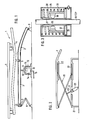
- Nachfolgend wird die Erfindung anhand der Zeichnung noch genauer erläutert, in der bevorzugte Ausführungsbeispiele der Erfindung in schematisierter Form dargestellt sind. Dabei zeigt
- Fig. 1 eine Seitenansicht eines pneumatisch gefederten Tragenlagerungsgestelles,
- Fig. 2 eine abgewandelte Ausführungsform eines erfindungsgemäßen Tragenlagerungsgestelles und
- Fig. 3 ein schematisiertes Schnittbild der pneumatisch betätigbaren Bremse.
- Einander entsprechende Teile haben in allen Figuren gleiche Bezugszeichen.
- Nach Fig. 1 ist auf dem Boden eines Krankenfahrzeuges eine Krankentragenbühne 1 angeordnet, welches im wesentlichen aus einem Rahmengestell 2 besteht, dessen beide Längsträger 3 als U-Schienen ausgebildet sind, in denen ein einen oberen Gestellrahmen bildender Lagerungsschlitten 4 in Längsrichtungrichtung verschiebbar mittels Rollen 5 geführt ist.
- Der Tragenlagerungsschlitten 4 dient zur Aufnahme einer Krankentrage 6, die ihrerseits mittels ihrer Füße 7 auf den Längsschienen des Schlittens 4 aufruht und auf demselben arretiert werden kann.
- Das Rahmengestell 2 und damit die gesamte Krankentragenbühne 1 ist an ihrem der nicht dargestellten Hecktür des Krankenfahrzeuges zugewandten hinteren Ende in einem Gelenk 8 mit waagerechter Querachse am Boden schwenkbar gelagert und an seinem vorderen Ende durch ein Scherensystem 9, welches z.B. aus zwei beiderseits der lotrechten Mittelebene der Krankentragenbühne angeordnete Lenkerpaare gebildet wird, in Höhenrichtung geführt bzw. gegen seitliches Ausweichen gesichert. Bei entsprechend stabiler Ausbildung des Gelenkes 8 kann das Scherensystem 9 gegebenenfalls auch entfallen.
- Zur Abfederung des Tragengestelles dient eine pneumatische Federung 10, welche einen mit dem Rahmengestell 2 verbundenen Stößel 12 aufweist, welcher in an sich bekannter Weise auf der pneumatisch abgestützten Membrane 13 eines pneumatischen Druckgefäßes 14 abgestützt ist. Dem Innenraum des Druckgefäßes 14 kann über eine Leitung 15 pneumatisches Medium von einer nicht dargestellten Druckquelle zugeführt werden.
- Das Druckgefäß 14 ist an einem am Boden montierten Bock 16 befestigt, an dem außerdem eine pneumatisch betätigbare Bremse 17 angeordnet ist, die mit dem Stößel 12 zusammenwirkt. Bei Arretierung des Stößels 12 wird das Rahmengestell 2 unfederbar festgehalten.
- Bei der in Fig. 2 dargestellten Krankentragenbühne ist das Rahmengestell 2 mittels eines Scherengestelles 20 abgestützt, dessen Scherenarme an ihren in der Zeichnung linken Enden am Rahmengestell 2 bzw. einem Sockelrahmen 21 um Querachsen schwenkbar gelagert sind, während die anderen Enden der Scherenarme am Rahmengestell 2 sowie am Sockelrahmen 21 in Führungskulissen 22 schwenk- und verschiebbar gelagert sind. Damit kann das Scherengestell 20 mittels eines pneumatischen Kolben-Zylinder-Aggregates 23, welches mit einer nicht dargestellten pneumatischen Druckquelle verbunden und zwischen dem einen Scherenarm des Scherengestelles 20 sowie dem Boden bzw. dem Sockelrahmen 21 angeordnet ist, in verschiedene Höhen verstellt werden, wobei aufgrund der Kompressibilität des Pneumatikmediums in jeder Höheneinstellung eine Federung des Rahmengestelles 2 möglich bleibt.
- Zur Ausschaltung der Federung ist hier am Zylinder des Kolben-Zylinder-Aggregates die pneumatisch betätigte Bremse 17 angeordnet, welche mit der Kolbenstange 23' des Kolben-Zylinder-Aggregates zusammenwirkt.
- Gemäß Fig. 3 besitzt die pneumatisch betätigbare Bremse ein ringförmiges Gehäuse 25, dessen axiale Öffnung vom Stößel 12 (vgl. Fig. 1) bzw. der Kolbenstange 23' (vgl. Fig.2) durchsetzt wird. Innerhalb des Gehäuses 25 befindet sich ein volumenveränderlicher Ringraum 26, welcher mittels eines ringförmigen Kolbens 27 abgeschlossen ist, der innerhalb des Gehäuses 25 verschiebbar angeordnet ist. Eine Rückstellfeder 28 sucht den Ringkolben 27 in Fig. 3 nach oben in eine Ruhelage zu schieben, während in den Ringraum 26 eingeleitetes Pneumatikmedium den Ringkolben 27 gegen die Kraft der Feder 28 nach unten zu schieben vermag. Am Kolben 27 ist ein Zylinderteil 29 angeordnet, welches mittels entsprechender Lagerschalen od.dgl. zur Lagerung von Kugeln 30 dient, die bei Verschiebung des Kolbens 27 über die Rückseite von Bremskeilen 31 geschoben werden, die an der inneren Umfangswand des Gehäuses 25 angeordnet sind und aufgrund ihres keilförmigen Querschnittes bei Verschiebung der Kugeln 30 nach aufwärts zunehmend gegen die Kolbenstange 23' bzw. den Stößel 12 angedrückt werden und denselben unbeweglich gegenüber dem Gehäuse 25 festhalten. Wird der Kolben bei Druckverminderung im Ringraum 26 durch die Feder 28 wiederum zurückgeschoben, können die von den Kugeln 30 nunmehr freigegebenen Bremskeile 31 unter Einwirkung nicht dargestellter Rückholfedern von der Kolbenstange 23' bzw. dem Stößel 12 abheben, d.h. eine Federung der Krankentragenbühnen ist wiederum möglich.
Claims (5)
Priority Applications (1)
| Application Number | Priority Date | Filing Date | Title |
|---|---|---|---|
| AT84103873T ATE40288T1 (de) | 1984-01-24 | 1984-04-07 | Krankenliegengestell, insbesondere krankentragenbuehne. |
Applications Claiming Priority (2)
| Application Number | Priority Date | Filing Date | Title |
|---|---|---|---|
| DE8401865 | 1984-01-24 | ||
| DE8401865U | 1984-01-24 |
Publications (3)
| Publication Number | Publication Date |
|---|---|
| EP0150254A2 true EP0150254A2 (de) | 1985-08-07 |
| EP0150254A3 EP0150254A3 (en) | 1986-12-03 |
| EP0150254B1 EP0150254B1 (de) | 1989-01-25 |
Family
ID=6762713
Family Applications (1)
| Application Number | Title | Priority Date | Filing Date |
|---|---|---|---|
| EP84103873A Expired EP0150254B1 (de) | 1984-01-24 | 1984-04-07 | Krankenliegengestell, insbesondere Krankentragenbühne |
Country Status (3)
| Country | Link |
|---|---|
| EP (1) | EP0150254B1 (de) |
| AT (1) | ATE40288T1 (de) |
| DE (1) | DE3476333D1 (de) |
Cited By (9)
| Publication number | Priority date | Publication date | Assignee | Title |
|---|---|---|---|---|
| GB2203032A (en) * | 1987-02-12 | 1988-10-12 | Hoskins Ltd | Resiliently suspended load carrier |
| FR2636230A1 (fr) * | 1988-09-15 | 1990-03-16 | Heuliez Henri France Design | Dispositif de support auto-porteur pour brancard loge notamment dans un vehicule sanitaire |
| US5477575A (en) * | 1993-12-01 | 1995-12-26 | Siemens Aktiengesellschaft | Patient support mechanism for medical examination apparatus |
| DE19814233A1 (de) * | 1998-03-30 | 1999-10-07 | Mark Hanke | Fahrgerät für Krankentragen |
| US6282738B1 (en) * | 1998-08-07 | 2001-09-04 | Hill-Rom, Inc. | Ob/Gyn stretcher |
| US7533429B2 (en) | 1999-12-29 | 2009-05-19 | Hill-Rom Services, Inc. | Lift system for hospital bed |
| US7610637B2 (en) | 1999-12-29 | 2009-11-03 | Hill-Rom Services, Inc. | Lift system for hospital bed |
| CN108514476A (zh) * | 2017-05-12 | 2018-09-11 | 卡塞纳有限责任公司 | 用于担架的锚定系统 |
| WO2023129136A1 (en) * | 2021-12-28 | 2023-07-06 | Jelka, Llc | Ambulance shock-absorbing platform for stretcher |
Families Citing this family (3)
| Publication number | Priority date | Publication date | Assignee | Title |
|---|---|---|---|---|
| EP1286640B1 (de) | 2000-06-02 | 2009-08-05 | Hill-Rom Services, Inc. | Fussstütze für patientenliege |
| US7657953B2 (en) | 2005-11-17 | 2010-02-09 | Hill-Rom Services, Inc. | Birthing bed calf support |
| IT202100030476A1 (it) * | 2021-12-02 | 2022-03-02 | Francesco Dadone | Sistema di movimentazione di una base di supporto per barella |
Family Cites Families (3)
| Publication number | Priority date | Publication date | Assignee | Title |
|---|---|---|---|---|
| DE1910111C2 (de) * | 1969-02-28 | 1971-03-04 | Binz & Co | Tragenbuehne fuer Krankenwagen |
| DE2552344B2 (de) * | 1975-11-21 | 1979-09-06 | Christian Miesen Fahrzeug- Und Karosseriewerk Gmbh, 5300 Bonn | In einem Krankentransportfahrzeug angeordnetes, innerhalb des Krankenraumes durch einen Hubantrieb in verschiendene Höhenlagen einstellbares, abgefedertes Gestell |
| DE2948005C2 (de) * | 1979-11-29 | 1986-05-07 | Keiper Dynavit GmbH & Co, 6750 Kaiserslautern | Halterung für einen Sitzträger |
-
1984
- 1984-04-07 AT AT84103873T patent/ATE40288T1/de not_active IP Right Cessation
- 1984-04-07 EP EP84103873A patent/EP0150254B1/de not_active Expired
- 1984-04-07 DE DE8484103873T patent/DE3476333D1/de not_active Expired
Cited By (14)
| Publication number | Priority date | Publication date | Assignee | Title |
|---|---|---|---|---|
| GB2203032A (en) * | 1987-02-12 | 1988-10-12 | Hoskins Ltd | Resiliently suspended load carrier |
| GB2203032B (en) * | 1987-02-12 | 1990-05-02 | Hoskins Ltd | Resiliently suspended load carrier |
| FR2636230A1 (fr) * | 1988-09-15 | 1990-03-16 | Heuliez Henri France Design | Dispositif de support auto-porteur pour brancard loge notamment dans un vehicule sanitaire |
| US5477575A (en) * | 1993-12-01 | 1995-12-26 | Siemens Aktiengesellschaft | Patient support mechanism for medical examination apparatus |
| DE19814233A1 (de) * | 1998-03-30 | 1999-10-07 | Mark Hanke | Fahrgerät für Krankentragen |
| US6412126B2 (en) | 1998-08-07 | 2002-07-02 | Hill-Rom Services, Inc. | OB/GYN stretcher |
| US6282738B1 (en) * | 1998-08-07 | 2001-09-04 | Hill-Rom, Inc. | Ob/Gyn stretcher |
| US6618882B2 (en) | 1998-08-07 | 2003-09-16 | Hill-Rom Services, Inc. | Ob/Gyn stretcher |
| US6983501B2 (en) | 1998-08-07 | 2006-01-10 | Hill-Rom Services, Inc. | Ob/Gyn stretcher |
| US7533429B2 (en) | 1999-12-29 | 2009-05-19 | Hill-Rom Services, Inc. | Lift system for hospital bed |
| US7610637B2 (en) | 1999-12-29 | 2009-11-03 | Hill-Rom Services, Inc. | Lift system for hospital bed |
| US10251797B2 (en) | 1999-12-29 | 2019-04-09 | Hill-Rom Services, Inc. | Hospital bed |
| CN108514476A (zh) * | 2017-05-12 | 2018-09-11 | 卡塞纳有限责任公司 | 用于担架的锚定系统 |
| WO2023129136A1 (en) * | 2021-12-28 | 2023-07-06 | Jelka, Llc | Ambulance shock-absorbing platform for stretcher |
Also Published As
| Publication number | Publication date |
|---|---|
| DE3476333D1 (en) | 1989-03-02 |
| EP0150254B1 (de) | 1989-01-25 |
| ATE40288T1 (de) | 1989-02-15 |
| EP0150254A3 (en) | 1986-12-03 |
Similar Documents
| Publication | Publication Date | Title |
|---|---|---|
| DE69117204T2 (de) | Aufhängungseinrichtung mit einem Nockenunterstützungselement und einer federunterstützten Höhenverstellung | |
| EP0150254B1 (de) | Krankenliegengestell, insbesondere Krankentragenbühne | |
| EP0139939B1 (de) | Sitzträger für Stühle, insb. Arbeitsdrehstühle | |
| DE10238059B4 (de) | Federelement | |
| DE2538411A1 (de) | Tragenlagerungsgestell mit durch ein hydraulisches bzw. pneumatisches hilfsmittel anhebbarer tragenbuehne | |
| DE2363392A1 (de) | Verstellbarer sessel | |
| EP1047316B1 (de) | Höhenverstellbarer tisch oder dergleichen | |
| DE2035237A1 (de) | Fahrzeugsitz | |
| DE69104883T2 (de) | Operationstische. | |
| DE69500003T2 (de) | Gabelhubwagen mit Stabilisationsrädern | |
| DE4227954A1 (de) | Dreiradfahrzeug, insbesondere Flurförderzeug | |
| DE19821021C2 (de) | Rahmen für einen Rollstuhl | |
| DE8401865U1 (de) | Krankenliegengestell, insbesondere Krankentragenbühne | |
| DE3009195C2 (de) | Hublader, der innerhalb der Radbasis quergeteilt ist | |
| DE19524075C1 (de) | Bremseinrichtung für ein Flurförderfahrzeug | |
| DE2936617C2 (de) | ||
| AT500201A2 (de) | Vorrichtung zur sekundärfederung eines wagenkastens bei einem schienenfahrzeug mit einem aktiven federelement | |
| CH691266A5 (de) | Oberwalzenträger für Streckwerke von Spinnereimaschinen. | |
| DE2361623C3 (de) | ||
| DE3041926A1 (de) | Stuhl | |
| EP3085274B1 (de) | Stuhl | |
| DE10114702C1 (de) | Patientenliege | |
| EP0303125A1 (de) | Tragenlagerungsgestell | |
| DE2312632C3 (de) | Lenkrolle für Sitzmöbel | |
| DE2146801B2 (de) | Bremseinrichtung für Schienenfahrzeuge mit zwei an gegenüberliegenden Schienenflanschen anliegenden Bremsbacken |
Legal Events
| Date | Code | Title | Description |
|---|---|---|---|
| PUAI | Public reference made under article 153(3) epc to a published international application that has entered the european phase |
Free format text: ORIGINAL CODE: 0009012 |
|
| AK | Designated contracting states |
Designated state(s): AT DE FR GB IT NL SE |
|
| PUAL | Search report despatched |
Free format text: ORIGINAL CODE: 0009013 |
|
| AK | Designated contracting states |
Kind code of ref document: A3 Designated state(s): AT DE FR GB IT NL SE |
|
| 17P | Request for examination filed |
Effective date: 19870122 |
|
| 17Q | First examination report despatched |
Effective date: 19880325 |
|
| ITF | It: translation for a ep patent filed | ||
| GRAA | (expected) grant |
Free format text: ORIGINAL CODE: 0009210 |
|
| AK | Designated contracting states |
Kind code of ref document: B1 Designated state(s): AT DE FR GB IT NL SE |
|
| REF | Corresponds to: |
Ref document number: 40288 Country of ref document: AT Date of ref document: 19890215 Kind code of ref document: T |
|
| REF | Corresponds to: |
Ref document number: 3476333 Country of ref document: DE Date of ref document: 19890302 |
|
| ET | Fr: translation filed | ||
| GBT | Gb: translation of ep patent filed (gb section 77(6)(a)/1977) | ||
| PLBE | No opposition filed within time limit |
Free format text: ORIGINAL CODE: 0009261 |
|
| STAA | Information on the status of an ep patent application or granted ep patent |
Free format text: STATUS: NO OPPOSITION FILED WITHIN TIME LIMIT |
|
| 26N | No opposition filed | ||
| PGFP | Annual fee paid to national office [announced via postgrant information from national office to epo] |
Ref country code: DE Payment date: 19900308 Year of fee payment: 7 |
|
| PGFP | Annual fee paid to national office [announced via postgrant information from national office to epo] |
Ref country code: GB Payment date: 19900331 Year of fee payment: 7 |
|
| PGFP | Annual fee paid to national office [announced via postgrant information from national office to epo] |
Ref country code: FR Payment date: 19900417 Year of fee payment: 7 |
|
| PGFP | Annual fee paid to national office [announced via postgrant information from national office to epo] |
Ref country code: SE Payment date: 19900423 Year of fee payment: 7 |
|
| PGFP | Annual fee paid to national office [announced via postgrant information from national office to epo] |
Ref country code: AT Payment date: 19900425 Year of fee payment: 7 |
|
| ITTA | It: last paid annual fee | ||
| PGFP | Annual fee paid to national office [announced via postgrant information from national office to epo] |
Ref country code: NL Payment date: 19900430 Year of fee payment: 7 |
|
| PG25 | Lapsed in a contracting state [announced via postgrant information from national office to epo] |
Ref country code: GB Effective date: 19910407 Ref country code: AT Effective date: 19910407 |
|
| PG25 | Lapsed in a contracting state [announced via postgrant information from national office to epo] |
Ref country code: SE Effective date: 19910408 |
|
| PG25 | Lapsed in a contracting state [announced via postgrant information from national office to epo] |
Ref country code: NL Effective date: 19911101 |
|
| GBPC | Gb: european patent ceased through non-payment of renewal fee | ||
| NLV4 | Nl: lapsed or anulled due to non-payment of the annual fee | ||
| PG25 | Lapsed in a contracting state [announced via postgrant information from national office to epo] |
Ref country code: FR Effective date: 19911230 |
|
| PG25 | Lapsed in a contracting state [announced via postgrant information from national office to epo] |
Ref country code: DE Effective date: 19920201 |
|
| REG | Reference to a national code |
Ref country code: FR Ref legal event code: ST |
|
| EUG | Se: european patent has lapsed |
Ref document number: 84103873.0 Effective date: 19911108 |