EP0150321B1 - Abluftleuchte für eine Unterdruckdecke - Google Patents
Abluftleuchte für eine Unterdruckdecke Download PDFInfo
- Publication number
- EP0150321B1 EP0150321B1 EP84114327A EP84114327A EP0150321B1 EP 0150321 B1 EP0150321 B1 EP 0150321B1 EP 84114327 A EP84114327 A EP 84114327A EP 84114327 A EP84114327 A EP 84114327A EP 0150321 B1 EP0150321 B1 EP 0150321B1
- Authority
- EP
- European Patent Office
- Prior art keywords
- exhaust air
- roof
- housing
- reflector
- hole
- Prior art date
- Legal status (The legal status is an assumption and is not a legal conclusion. Google has not performed a legal analysis and makes no representation as to the accuracy of the status listed.)
- Expired
Links
- 238000010137 moulding (plastic) Methods 0.000 claims 1
- 241000446313 Lamella Species 0.000 description 1
- 239000003990 capacitor Substances 0.000 description 1
- 230000001419 dependent effect Effects 0.000 description 1
- 239000002991 molded plastic Substances 0.000 description 1
- 239000004033 plastic Substances 0.000 description 1
- 239000007858 starting material Substances 0.000 description 1
Images

Classifications
-
- F—MECHANICAL ENGINEERING; LIGHTING; HEATING; WEAPONS; BLASTING
- F24—HEATING; RANGES; VENTILATING
- F24F—AIR-CONDITIONING; AIR-HUMIDIFICATION; VENTILATION; USE OF AIR CURRENTS FOR SCREENING
- F24F13/00—Details common to, or for air-conditioning, air-humidification, ventilation or use of air currents for screening
- F24F13/02—Ducting arrangements
- F24F13/06—Outlets for directing or distributing air into rooms or spaces, e.g. ceiling air diffuser
- F24F13/078—Outlets for directing or distributing air into rooms or spaces, e.g. ceiling air diffuser combined with lighting fixtures
Definitions
- the invention relates to an exhaust air lamp for a rod-shaped lamp according to the preamble of claim 1.
- the invention has for its object to significantly reduce the housing height of an exhaust air lamp of the type mentioned, while still maintaining the largest possible range of adjustable operating points and a low flow noise.
- the invention enables the successful use of the known exhaust air technology in likewise known lamps with a very low housing height, in which the housing roof is part of the channel-shaped reflector.
- a fluidically sufficient area for the individual exhaust air openings is achieved in that each exhaust air opening extends over a housing edge with a roof-side cutout into the surface of the housing roof, but only to such an extent that it is still covered by the side reflector underneath and therefore not through the light outlet opening is visible.
- the two cutouts are preferably rectangular and have the same cutout depth.
- the cutout length is preferably in a range from 150 to 300 mm with a gap height of the exhaust air gap between the housing roof and the side reflector of 5 to 15 mm.
- plastic covers which consist of several sections separated by notches and which can be resiliently clamped between the longitudinal edges of an exhaust air opening with the aid of undercut strips.
- An exhaust air lamp according to the invention can also be connected directly to an exhaust air duct via an exhaust air connector: an exhaust air connector with two partial flanges arranged at an appropriate angle to one another is used and placed on a central exhaust air opening of the housing; the other exhaust openings are completely closed by a cover.
- the two partial flanges can be designed identically, so that it can be connected to the lamp housing in two positions: With the same exhaust air duct, an exhaust air duct is then possible parallel or perpendicular to the light outlet opening of the exhaust air lamp.
- the housing of the exhaust air lamp consists of side walls 11, 12 which enclose a light outlet opening 100 and which are connected to one another by a housing roof 10 parallel to the light outlet opening.
- Two rod-shaped lamps 3 and two channel-shaped reflectors 20 assigned to them are arranged in the housing, which together form a reflector insert 2 and each consist of side reflectors 201, 202 and a roof reflector 200, which is designed as a reflecting section of the housing roof 10.
- An exhaust air gap 204 is left free between the side reflectors 201, 202 and the housing roof 10, the gap height d of which is between 5 and 15 mm.
- the accessory 4 (choke / starter / capacitors) is arranged on the housing roof 10 in the region of a V-shaped web 21 which is formed by the two adjacent side reflectors 202 of the two adjacent reflectors 20 and which covers these accessories. This design enables a very low housing height e, which is less than 100 mm, in particular 80 mm.
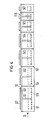
- each exhaust opening 110 is arranged symmetrically to the central transverse plane Q (FIG. 2).
- Each exhaust air opening consists of a side cutout 1101 with the cutout depth a2 and a roof-side cutout 1102 with the cutout depth a1.
- These cutouts which thus overlap the housing edge 111, have a rectangular cross section.
- the roof-side cutout depth is a1 equal to or smaller than the reflector width c, which is determined by the projection of the side reflector 201 adjacent to the side wall 11 onto the housing roof 10.
- each exhaust air opening is chosen so that the maximum exhaust air flow can be extracted without disturbing noise; it is between 150 and 300 mm and is to be dimensioned larger the smaller the gap height d is dimensioned.
- the gap height d is preferably 10 mm, the lateral and roof-side cutout depth a2 and a1 is 20 mm and the cutout length b is 200 mm; the total area of the two cutouts of each exhaust air opening is then 80 cm 2 . If all six exhaust air openings are completely open, an exhaust air flow of 190 m 3 per hour with a pressure drop of 7 N / m 2 and a sound level of 25 dB can be achieved with such an exhaust air lamp, and a volume flow of 300 m at a sound level of 35 dB Cope with 3 per hour at a pressure drop of 19 N / m 2 .
- each cover element - FIGS. 3, 4 - is a molded plastic part with two legs 51, 52 standing perpendicular to one another, which have ribs 53 on the inside for stiffening and on the Each have a strip 511, 521 with a nose-shaped cross section on the outside. These strips have undercuts and are arranged such that they overlap the longitudinal edges of the exhaust air opening and thereby hold the cover element 5 in the exhaust air opening. Since the areas of the legs 51, 52 are somewhat larger than the cutouts 1101, 1102 of the housing, the exhaust air opening is completely closed by the cover element 5.
- the cover element 5 is divided in its longitudinal direction by notches 50 into several sections 501 to 507 of different lengths: by separating one or more such sections along such a notch, an exhaust air opening of the housing can thus also be partially covered.
- a targeted fine adjustment of the exhaust air flow and / or pressure drop can be achieved, if necessary in conjunction with several completely covered exhaust air openings.
- the exhaust air lamp which is initially intended for a vacuum ceiling, can also be used in connection with an exhaust air duct:
- a central exhaust air opening is closed by an exhaust air connector 6, which has two identical cutouts 1101, 1102 Has partial flanges 61, 62; the remaining exhaust openings are completely closed by cover elements 5.
- the bisector W between the cutouts 1101, 1102 of each exhaust air opening and thus between the partial flanges 61, 62 of the exhaust air connector encloses an angle of 45 ° with the light outlet opening 100 and with the longitudinal axis 600 of the connecting pipe piece 60: Two connection options can then be realized with the same exhaust air connector , namely connecting pipe piece 60 parallel or perpendicular to the light exit opening 100.
Landscapes
- Engineering & Computer Science (AREA)
- Chemical & Material Sciences (AREA)
- Combustion & Propulsion (AREA)
- Mechanical Engineering (AREA)
- General Engineering & Computer Science (AREA)
- Arrangement Of Elements, Cooling, Sealing, Or The Like Of Lighting Devices (AREA)
- Ventilation (AREA)
- Eye Examination Apparatus (AREA)
- Vehicle Interior And Exterior Ornaments, Soundproofing, And Insulation (AREA)
- Duct Arrangements (AREA)
Description
- Die Erfindung betrifft eine Abluftleuchte für eine stabförmige Lampe gemäß Oberbegriff von Anspruch 1.
- Die Seitenwände einer solchen, aus der DE-PS 3 013 147 bekannten Abluftleuchte hat nur verhältnismäßig wenige - maximal 10 - Abluftöffnungen, die jedoch einen ungewöhnlich großen Querschnitt von mindestens 20 cm2 haben. Durch vollständige oder teilweise Abdeckung dieser Abluftöffnungen durch Abdeckungen mit definierten Schneidrillen läßt sich das mit einer solchen Abluftleuchte absaugbare Luftvolumen und der dabei jeweils gewünschte Druckabfall in einem sehr weiten Bereich einfach einstellen.
- In dem bekannten Fall liegen diese großen Abluftöffnungen vollständig in den Seitenwänden des Gehäuses; daraus resultiert eine verhältnismäßig große Gehäusehöhe, wenn ein bestimmter maximaler Schallpegel bei geforderten Maximalwerten für Volumenstrom und Druckabfall nicht überschritten werden soll.
- Der Erfindung liegt die Aufgabe zugrunde, die Gehäusehöhe einer Abluftleuchte einer eingangs genannten Art wesentlich zu reduzieren, dabei aber trotzdem einen möglichst großen Bereich von einstellbaren Arbeitspunkten und ein niedriges Strömungsrauschen beizubehalten.
- Diese Aufgabe ist durch die im Kennzeichen von Anspruch 1 angegebenen Merkmale gelöst.
- Die Erfindung ermöglicht die erfolgreiche Anwendung der bekannten Ablufttechnik bei ebenfalls bekannten Leuchten mit sehr niedriger Gehäusehöhe, bei denen das Gehäusedach Teil des rinnenförmigen Reflektors ist. Eine strömungstechnisch ausreichende Fläche für die einzelnen Abluftöffnungen wird dabei dadurch erreicht, daß sich jede Abluftöffnung über eine Gehäusekante mit einem dachseitigen Ausschnitt in die Fläche des Gehäusedaches hineinerstreckt, jedoch nur so weit, daß sie durch den darunterliegenden Seitenreflektor noch abgedeckt und daher durch die Lichtaustrittsöffnung nicht sichtbar ist.
- Aus der DE-OS 3 029 812 ist es zwar bekannt, eine Abluftöffnung durch Ausschnitte in einer Seitenwand und im Gehäusedach des Leuchtengehäuses zu bilden. In dem bekannten Fall handelt es sich jedoch um eine Abluftöffnung zum Anschluß eines Abluftstutzens, wobei ein gesonderter Dachspiegel vorhanden ist, was zu einer entsprechend großen Gehäusehöhe führt; außerdem erstreckt sich der dachseitige Ausschnitt über den gesamten Dachspiegel hinweg.
- Vorzugsweise sind die beiden Ausschnitte rechteckförmig und haben gleiche Ausschnittiefe. Die Ausschnittlänge liegt vorzugsweise in einem Bereich von 150 bis 300 mm bei einer Spalthöhe des Abluftspaltes zwischen Gehäusedach und Seitenreflektor von 5 bis 15 mm.
- Zur vollständigen oder teilweisen Abdeckung einer jeden Abluftöffnung dienen Abdeckungen aus Kunststoff, die aus mehreren, durch Kerben voneinander getrennten Abschnitten bestehen und die mit Hilfe von hinterschnittenen Leisten zwischen den Längskanten einer Abluftöffnung federnd einklemmbar sind.
- Eine erfindungsgemäße Abluftleuchte kann auch über einen Abluftstutzen direkt an einen Abluftkanal angeschlossen werden: Hierzu wird ein Abluftstutzen mit zwei entsprechend winklig gegeneinander angeordneten Teilflanschen verwendet und auf eine mittlere Abluftöffnung des Gehäuses aufgesetzt; die übrigen Abluftöffnungen werden durch eine Abdeckung vollständig geschlossen. Die beiden Teilflansche können hierbei identisch ausgeführt sein, so daß er in zwei Positionen mit dem Leuchtengehäuse verbindbar ist: Mit demselben Abluftstutzen ist dann eine Abluftführung parallel oder senkrecht zur Lichtaustrittsöffnung der Abluftleuchte möglich.
- Weitere vorteilhafte Ausgestaltungen der Erfindung sind in den Unteränsprüchen gekennzeichnet.
- Die Erfindung wird anhand des in den Figuren dargestellten Ausführungsbeispieles näher erläutert; es zeigen
- Fig. 1 einen schematischen Querschnitt durch eine zweilampige Abluftleuchte (Schnittlinie I-I in Fig. 2),
- Fig. 2 eine Seitenansicht dieser Abluftleuchte in verkleinertem Maßstab,
- Fig. 3 ein Abdeckelement für eine Abluftöffnung in Stirnansicht (in Richtung des Pfeiles 111 in Fig. 4) und
- Fig. 4 eine Seitenansicht des Abdeckelementes in Richtung des Pfeiles IV in Fig. 3.
- Das Gehäuse der Abluftleuchte besteht aus Seitenwänden 11, 12, die eine Lichtaustrittsöffnung 100 einschließen und die durch ein Gehäusedach 10 parallel zu der Lichtaustrittsöffnung miteinander verbunden sind. In dem Gehäuse sind zwei stabförmige Lampen 3 und zwei diesen zugeordneten, rinnenförmige Reflektoren 20 angeordnet, die zusammen einen Reflektoreinsatz 2 bilden und jeweils aus Seitenreflektoren 201, 202 und einem Dachreflektor 200 bestehen, der als reflektierender Abschnitt des Gehäusedaches 10 ausgebildet ist.
- Zwischen den Seitenreflektoren 201, 202 und dem Gehäusedach 10 ist ein Abluftspalt 204freigelassen, dessen Spalthöhe d zwischen 5 und 15 mm liegt. Das Zubehör 4 (Drossel/Starter/Kondensatoren) ist an dem Gehäusedach 10 im Bereich eines V-förmigen Steges 21 angeordnet, der von den beiden benachbarten Seitenreflektoren 202 der beiden benachbarten Reflektoren 20 gebildet wird und der dieses Zubehör abdeckt. Diese Bauform ermöglicht eine sehr geringe Gehäusehöhe e, die unter 100 mm, insbesondere bei 80 mm liegt.
- Im Bereich jeder Seitenwand 11, 12 des Gehäuses sind drei Abluftöffnungen 110 symmetrisch zur mittleren Querebene Q (Fig. 2) angeordnet. Jede Abluftöffnung besteht aus einem seitlichen Ausschnitt 1101 mit der Ausschnittstiefe a2 und einem dachseitigen Ausschnitt 1102 mit der Ausschnittstiefe a1. Diese Ausschnitte, die somit die Gehäusekante 111 übergreifen, haben rechteckigen Querschnitt. Die dachseitige Ausschnittiefe a1 ist gleich oder kleiner als die Reflektorbreite c, die bestimmt ist durch die Projektion des der Seitenwand 11 benachbarten Seitenreflektors 201 auf das Gehäusedach 10.
- Die Ausschnittlänge b - Fig. 2 - jeder Abluftöffnung ist es so gewählt, daß sich der maximale Abluftstrom ohne störendes Rauschen absaugen läßt; er liegt zwischen 150 und 300 mm und ist um so größer zu bemessen, je geringer die Spalthöhe d bemessen ist.
- Vorzugsweise beträgt die Spalthöhe d gleich 10 mm, die seitliche und dachseitige Ausschnittiefe a2 und a1 gleich 20 mm und die Ausschnittlänge b gleich 200 mm; die gesamte Fläche der beiden Ausschnitte jeder Abluftöffnung liegt dann bei 80 cm2. Wenn alle sechs Abluftöffnungen vollständig offen sind, läßt sich mit einer solchen Abluftleuchte ein Abluftstrom von 190 m3 pro Stunde bei einem Druckabfall von 7 N/m2 und einem Schallpegel von 25 dB, bei einem Schallpegel von 35 dB sogar ein Volumenstrom von 300 m3 pro Stunde bei einem Druckabfall von 19 N/m2 bewältigen.
- Mit der Erfindung lassen sich aber auch gleiche oder sogar höhere Druckabfälle bei niedrigerem Abluftstrom einstellen; hierzu braucht lediglich ein Teil der gesamten Fläche aller Abluftöffnungen durch Abdeckelement 5 abgedeckt zu werden: Jedes Abdeckelement - Fig. 3, 4 - ist ein Kunststofformteil mit zwei senkrecht aufeinanderstehenden Schenkeln 51, 52, die auf der Innenseite Rippen 53 zur Versteifung aufweisen und auf der Außenseite jeweils eine Leiste 511, 521 mit nasenförmigem Querschnitt aufweisen. Diese Leisten haben Hinterschneidungen und sind so angeordnet, daß sie die Längskanten der Abluftöffnung übergreifen und dadurch das Abdeckelement 5 in der Abluftöffnung halten. Da die Flächen der Schenkel 51, 52 etwas größer als die Ausschnitte 1101, 1102 des Gehäuses sind, ist die Abluftöffnung durch das Abdeckelement 5 vollständig verschlossen.
- Gemäß Fig. 4 ist das Abdeckelement 5 in seiner Längsrichtung durch Kerben 50 in mehrere, unterschiedlich lange Abschnitte 501 bis 507 unterteilt: Durch Abtrennen eines oder mehrerer solcher Abschnitte entlang einer solchen Kerbe läßt sich somit eine Abluftöffnung des Gehäuses auch teilweise abdecken. Dadurch läßt sich - gegebenenfalls in Verbindung mit mehreren vollständig abgedeckten Abluftöffnungen - eine gezielte Feineinstellung von Abluftstrom und/oder Druckabfall erreichen.
- Anhand von Fig. 1 ist schließlich noch gezeigt, daß sich die zunächst für eine Unterdruckdecke bestimmte Abluftleuchte auch in Verbindung mit einem Abluftkanal einsetzen läßt: Hierzu wird eine mittlere Abluftöffnung durch einen Abluftstutzen 6 abgeschlossen, der zwei identische, zu den Ausschnitten 1101, 1102 passende Teilflansche 61, 62 hat; die übrigen Abluftöffnungen sind durch Abdeckelemente 5 vollständig geschlossen. Die Winkelhalbierende W zwischen den Ausschnitten 1101,1102 jeder Abluftöffnung und damit zwischen den Teilflanschen 61, 62 des Abluftstutzens schließt mit der Lichtaustrittsöffnung 100 und mit der Längsachse 600 des Anschlußrohrstückes 60 einen Winkel von 45° ein: Mit demselben Abluftstutzen lassen sich dann zwei Anschlußmöglichkeiten realisieren, nämlich Anschlußrohrstück 60 parallel oder senkrecht zur Lichtaustrittsöffnung 100.
-
- 10 Gehäusedach
- 11 Seitenwand
- 12 Seitenwand
- 100 Lichtaustrittsöffnung
- 110 Abluftöffnung
- 111 Gehäusekante
- 1101 seitlicher Ausschnitt
- 1102 dachseitiger Ausschnitt
- 2 Reflektoreinsatz
- 20 rinnenförmiger Reflektor
- 200 Dachreflektor
- 201 Seitenreflektor
- 202 Seitenreflektor
- 21 Steg
- 203 Querlamelle
- 204 Abluftspalt
- 3 Lampe
- 4 Zubehör
- 5 Abdeckelement
- 50 Kerbe
- 51 Schenkel
- 52 Schenkel
- 53 Rippe
- 511 Leiste
- 521 Leiste
- 501 bis 507 Abschnitte
- 6 Abluftstutzen
- 61,62 Teilflansch
- 60 Anschlußrohrstück
- 600 Längsachse
- a Ausschnittiefe
- b Ausschnittlänge
- c Reflektorbreite
- d Spalthöhe
- e Gehäusehöhe
Claims (13)
Priority Applications (1)
| Application Number | Priority Date | Filing Date | Title |
|---|---|---|---|
| AT84114327T ATE42141T1 (de) | 1984-01-25 | 1984-11-27 | Abluftleuchte fuer eine unterdruckdecke. |
Applications Claiming Priority (2)
| Application Number | Priority Date | Filing Date | Title |
|---|---|---|---|
| DE19848402071U DE8402071U1 (de) | 1984-01-25 | 1984-01-25 | Abluftleuchte fuer eine unterdruckdecke |
| DE8402071U | 1984-01-25 |
Publications (3)
| Publication Number | Publication Date |
|---|---|
| EP0150321A2 EP0150321A2 (de) | 1985-08-07 |
| EP0150321A3 EP0150321A3 (en) | 1987-04-29 |
| EP0150321B1 true EP0150321B1 (de) | 1989-04-12 |
Family
ID=6762781
Family Applications (1)
| Application Number | Title | Priority Date | Filing Date |
|---|---|---|---|
| EP84114327A Expired EP0150321B1 (de) | 1984-01-25 | 1984-11-27 | Abluftleuchte für eine Unterdruckdecke |
Country Status (4)
| Country | Link |
|---|---|
| EP (1) | EP0150321B1 (de) |
| AT (1) | ATE42141T1 (de) |
| DE (2) | DE8402071U1 (de) |
| ZA (1) | ZA85562B (de) |
Family Cites Families (4)
| Publication number | Priority date | Publication date | Assignee | Title |
|---|---|---|---|---|
| US3010378A (en) * | 1959-10-22 | 1961-11-28 | Thomas Industries Inc | Lighting and ventilating system |
| DE1489531A1 (de) * | 1965-12-29 | 1969-04-03 | Siemens Ag | Deckeneinbauleuchte fuer einen klimatisierten Raum |
| DE2740098C2 (de) * | 1977-09-06 | 1982-04-08 | Siemens AG, 1000 Berlin und 8000 München | Zuluftkasten |
| DE3029812C2 (de) * | 1980-08-06 | 1984-06-14 | Siemens AG, 1000 Berlin und 8000 München | Abluftleuchte |
-
1984
- 1984-01-25 DE DE19848402071U patent/DE8402071U1/de not_active Expired
- 1984-11-27 EP EP84114327A patent/EP0150321B1/de not_active Expired
- 1984-11-27 AT AT84114327T patent/ATE42141T1/de not_active IP Right Cessation
- 1984-11-27 DE DE8484114327T patent/DE3477690D1/de not_active Expired
-
1985
- 1985-01-24 ZA ZA85562A patent/ZA85562B/xx unknown
Also Published As
| Publication number | Publication date |
|---|---|
| ZA85562B (en) | 1986-09-24 |
| DE8402071U1 (de) | 1984-04-26 |
| EP0150321A3 (en) | 1987-04-29 |
| ATE42141T1 (de) | 1989-04-15 |
| DE3477690D1 (en) | 1989-05-18 |
| EP0150321A2 (de) | 1985-08-07 |
Similar Documents
| Publication | Publication Date | Title |
|---|---|---|
| DE3603839C2 (de) | ||
| DE68922245T2 (de) | Luftkasten mit drei Teilströmen. | |
| DE3013147C2 (de) | Abluftleuchte für eine Unterdruckdecke | |
| DE4037442A1 (de) | Anordnung zur laermverminderung bei staubsaugern | |
| DE102015014482A1 (de) | Filterelementeinheit für einen Luftfilter mit einer zweiteiligen durch Brücken verbundenen Dichtung | |
| DE102017000792A1 (de) | Filterelement mit optimierter Strömungsführung | |
| DE19526747A1 (de) | Luftströmungsrichtungs-Steuervorrichtung einer Klimaanlage | |
| EP0034354B1 (de) | Leuchtenraster mit gekrümmten Aussenreflektoren | |
| DE3441769A1 (de) | Lueftungsvorrichtung fuer raeume | |
| EP0150321B1 (de) | Abluftleuchte für eine Unterdruckdecke | |
| EP0359069A2 (de) | Verfahren zur Herstellung eines Leuchtenrasters | |
| EP0042539A2 (de) | Firstentlüftung an Dächern | |
| DE3034892C2 (de) | Leuchtenraster mit Außenreflektoren | |
| DE3940842A1 (de) | Bediengeraet fuer nachrichtentechnische geraete | |
| DE2842161C2 (de) | Lüftungsvorrichtung für Räume | |
| DE3519498A1 (de) | Parabolspiegelartiges reflektorelement fuer leuchtroehren | |
| DE19647043C1 (de) | Filter für eine Lüftungsanlage | |
| DE3237560C2 (de) | ||
| DE69105947T2 (de) | Lüftungsanlage. | |
| DE3041111C2 (de) | Rechteckiger Leuchtenrahmen | |
| EP0002701B1 (de) | Abluftleitvorrichtung für Abluftkanal | |
| EP0149053A2 (de) | Lüftungsvorrichtung für Räume | |
| EP0539843A2 (de) | In eine Öffnung der Motorhaube eines Kraftfahrzeuges einsetzbare Lüftungseinrichtung | |
| DE60203915T2 (de) | Einsatzmodul für modulare Messvorrichtung | |
| DE4429144A1 (de) | Schlitzauslaß |
Legal Events
| Date | Code | Title | Description |
|---|---|---|---|
| PUAI | Public reference made under article 153(3) epc to a published international application that has entered the european phase |
Free format text: ORIGINAL CODE: 0009012 |
|
| 17P | Request for examination filed |
Effective date: 19841205 |
|
| AK | Designated contracting states |
Designated state(s): AT CH DE IT LI SE |
|
| PUAL | Search report despatched |
Free format text: ORIGINAL CODE: 0009013 |
|
| AK | Designated contracting states |
Kind code of ref document: A3 Designated state(s): AT CH DE IT LI SE |
|
| 17Q | First examination report despatched |
Effective date: 19880119 |
|
| GRAA | (expected) grant |
Free format text: ORIGINAL CODE: 0009210 |
|
| AK | Designated contracting states |
Kind code of ref document: B1 Designated state(s): AT CH DE IT LI SE |
|
| PG25 | Lapsed in a contracting state [announced via postgrant information from national office to epo] |
Ref country code: SE Effective date: 19890412 Ref country code: IT Free format text: LAPSE BECAUSE OF FAILURE TO SUBMIT A TRANSLATION OF THE DESCRIPTION OR TO PAY THE FEE WITHIN THE PRESCRIBED TIME-LIMIT;WARNING: LAPSES OF ITALIAN PATENTS WITH EFFECTIVE DATE BEFORE 2007 MAY HAVE OCCURRED AT ANY TIME BEFORE 2007. THE CORRECT EFFECTIVE DATE MAY BE DIFFERENT FROM THE ONE RECORDED. Effective date: 19890412 |
|
| REF | Corresponds to: |
Ref document number: 42141 Country of ref document: AT Date of ref document: 19890415 Kind code of ref document: T |
|
| REF | Corresponds to: |
Ref document number: 3477690 Country of ref document: DE Date of ref document: 19890518 |
|
| PG25 | Lapsed in a contracting state [announced via postgrant information from national office to epo] |
Ref country code: AT Effective date: 19891127 |
|
| PG25 | Lapsed in a contracting state [announced via postgrant information from national office to epo] |
Ref country code: LI Effective date: 19891130 Ref country code: CH Effective date: 19891130 |
|
| PLBE | No opposition filed within time limit |
Free format text: ORIGINAL CODE: 0009261 |
|
| STAA | Information on the status of an ep patent application or granted ep patent |
Free format text: STATUS: NO OPPOSITION FILED WITHIN TIME LIMIT |
|
| 26N | No opposition filed | ||
| REG | Reference to a national code |
Ref country code: CH Ref legal event code: PL |
|
| PG25 | Lapsed in a contracting state [announced via postgrant information from national office to epo] |
Ref country code: DE Effective date: 19900801 |
|
| EUG | Se: european patent has lapsed |
Ref document number: 84114327.4 Effective date: 19890322 |