EP0150344A2 - Grue avec tour télescopique - Google Patents
Grue avec tour télescopique Download PDFInfo
- Publication number
- EP0150344A2 EP0150344A2 EP84114818A EP84114818A EP0150344A2 EP 0150344 A2 EP0150344 A2 EP 0150344A2 EP 84114818 A EP84114818 A EP 84114818A EP 84114818 A EP84114818 A EP 84114818A EP 0150344 A2 EP0150344 A2 EP 0150344A2
- Authority
- EP
- European Patent Office
- Prior art keywords
- rope
- tower
- area
- trolley
- guy
- Prior art date
- Legal status (The legal status is an assumption and is not a legal conclusion. Google has not performed a legal analysis and makes no representation as to the accuracy of the status listed.)
- Granted
Links
- 230000000694 effects Effects 0.000 description 2
- 241000282326 Felis catus Species 0.000 description 1
- 230000001154 acute effect Effects 0.000 description 1
- 238000012937 correction Methods 0.000 description 1
Images

Classifications
-
- B—PERFORMING OPERATIONS; TRANSPORTING
- B66—HOISTING; LIFTING; HAULING
- B66C—CRANES; LOAD-ENGAGING ELEMENTS OR DEVICES FOR CRANES, CAPSTANS, WINCHES, OR TACKLES
- B66C13/00—Other constructional features or details
- B66C13/04—Auxiliary devices for controlling movements of suspended loads, or preventing cable slack
- B66C13/10—Auxiliary devices for controlling movements of suspended loads, or preventing cable slack for preventing cable slack
-
- B—PERFORMING OPERATIONS; TRANSPORTING
- B66—HOISTING; LIFTING; HAULING
- B66C—CRANES; LOAD-ENGAGING ELEMENTS OR DEVICES FOR CRANES, CAPSTANS, WINCHES, OR TACKLES
- B66C23/00—Cranes comprising essentially a beam, boom, or triangular structure acting as a cantilever and mounted for translatory of swinging movements in vertical or horizontal planes or a combination of such movements, e.g. jib-cranes, derricks, tower cranes
- B66C23/18—Cranes comprising essentially a beam, boom, or triangular structure acting as a cantilever and mounted for translatory of swinging movements in vertical or horizontal planes or a combination of such movements, e.g. jib-cranes, derricks, tower cranes specially adapted for use in particular purposes
- B66C23/26—Cranes comprising essentially a beam, boom, or triangular structure acting as a cantilever and mounted for translatory of swinging movements in vertical or horizontal planes or a combination of such movements, e.g. jib-cranes, derricks, tower cranes specially adapted for use in particular purposes for use on building sites; constructed, e.g. with separable parts, to facilitate rapid assembly or dismantling, for operation at successively higher levels, for transport by road or rail
- B66C23/34—Self-erecting cranes, i.e. with hoisting gear adapted for crane erection purposes
- B66C23/342—Self-erecting cranes, i.e. with hoisting gear adapted for crane erection purposes with telescopic elements
Definitions
- the invention relates to a crane with a telescopic tower attached to an uppercarriage or to the rotating platform of a portal, the inner tower part of which can be extended at the upper end of the outer tower piece, which can be pivoted out of the outer tower piece, which can be pivoted upright during assembly about an articulation pin provided in its lower region inner support part of the boom is connected, at the outer end of which an outer support part of the boom is articulated, the support parts being provided with guides for the trolley, with two guy supports articulated in the area of the top of the tower, via the outer fixed points of which a rear guy cable is attached to a fixed point the superstructure or Portal runs, and with a guy support articulated in the area of the articulated connection of the support parts of the boom, two further guy cables being fastened to the outer end of the central guy support articulated in the area of the tower top, one of which fastens in the area of the articulated connection of the support parts and the other runs over a fixed point at the outer end of the guy support articulated in the area between the
- DE-OS 33 22 268, 26 14 223, 29 14 265 and 28 31 286 as well as DE-GMS 80 09 033 known telescopic cranes of this and a similar type need to erect the outer tower piece with the inner tower piece retracted and the support parts of the boom, if necessary, folded down Extending the inner tower section from the outer tower section and / or special hydraulic devices, telescopic pulley blocks and / or assembly winches for opening and pivoting the boom.
- the object of the invention is therefore to provide a crane with a telescopic tower of the type mentioned, which can be erected and assembled in a simple manner with the already existing hoisting and trolley winches without additional hydraulic presses, assembly hoists or assembly winches.
- both winches are arranged in the area of the uppercarriage or the rotating platform, that the trolley rope has at least one rope pulley fastened in the area of the lower end of the outer tower piece, one rope pulley attached in the area of the upper end of the outer tower piece, one in the lower one Area of the inner tower piece mounted rope pulley, in the area of the tower tip of the outer end of the outer support part of the boom and in the area of the articulated Connection of the carrier parts mounted rope pulleys runs to a fixed point on the trolley and that the hoist rope runs over intermediate rope pulleys, deflection pulleys of the trolley and the role or rollers of the crane hook to its fixed point at the outer end of the outer carrier part.
- the crane according to the invention can only be erected using the trolley winch. For this it is first necessary that the trolley is fixed to the folded-down support parts of the jib so that the end of the trolley rope is fixed. Furthermore, before the outer tower piece folded onto the revolving stage is erected, the inner tower piece which has been retracted into it is blocked in the latter.
- the outer tower piece is pivotally mounted in a carrier piece of the rotating platform at such a distance above a deflecting roller at its lower end that an erecting torque is generated around the articulated bolt by actuating the trolley winch. As soon as the outer tower section has been erected into its vertical position by the trolley winch, it is firmly bolted to the rotating platform by at least one further bolt connection.
- the locking of the inner tower section with the outer tower section is released, so that the inner tower section can be extended from the outer tower section by actuating the trolley winch again.
- the inner tower piece is then locked to the outer tower piece by bolt connections or the like.
- the guy ropes guided over the guy supports, the rear guy rope of which is connected to the rotating platform are tightened when the outer tower section is extended, the folded-up support parts of the jib are opened and the jib is pivoted into its end position.
- the trolley can be moved via the trolley winch in the direction of the outer end of the boom, so that only devices are left must be provided in order to be able to move the trolley in the opposite direction.
- This device can consist in that the trolley is connected to the top of the tower via a rope which forms a loop in the area of the tower, in which a weight is suspended.
- the weight has the effect that a train always acts on the trolley in the direction of the tower, so that it is moved from the trolley winch towards the tower by appropriately lowering the trolley cable.
- the same effect can also be achieved if the boom in the assembled position is pivoted upwards beyond the horizontal, ie forms an acute angle with the horizontal.
- the hoist rope is reeved in a pulley-like manner via rope pulleys mounted on the rear guy rope and on the rotating platform.
- This configuration makes it possible to tension the rear guy rope over the hoist winch and thereby open and swing out the support parts of the boom.
- the guy rope is tightly connected to the turntable, so that the pulley is relieved or can be dispensed with entirely. Since the boom can be opened and pivoted independently of the extension of the inner tower section, the boom can also be raised when the inner tower section is retracted into the outer tower section or in all intermediate positions.
- this can also be done instead of the trolley weight hanging in the rope loop can be blocked in predetermined positions.
- the hoisting rope is guided to the rope pulleys of the trolley via rope pulleys mounted at the upper end of the outer tower piece, at the lower end of the inner tower piece and in the area of the tower tip.
- the inner telescopic section is telescoped over the hoist rope via the hoist winch, the crane hook being moved against the trolley as far as it will go, and the extension arm being opened and swung out at the same time as being extended, the trolley hoist not initially needs to be actuated because the cable extension of the trolley travel cable gained by the extension extends it in the area of the jib and thereby enables the jib to be opened and swung out. Any necessary corrections can be made by operating the trolley winch accordingly.
- the cable pulley attached to the lower end of the inner tower piece is detachable and can be attached as a bottom block of a block and tackle to a cable that runs over deflection pulleys and the other end of which is connected to the rear guy cable.
- the boom in the retracted position of the inner tower section or in intermediate positions, the boom can be opened and swung out by actuating the hoist winch.
- the cable pulley can be detached from the rotating platform and provided as a bottom block with a crane hook for ballasting the crane.
- the outer tower section can be rocked over the trolley winch and for ballasting it can be moved with a crane hook Lift and lower the provided bottom block over the hoist winch.
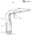
- the telescopic crane shown schematically in FIGS. 1 and 2 has a flat portal 1 with support feet, about the vertical axis 2 of which the rotating stage 3 provided with a conventional rotary drive can be rotated.
- Lateral stands 4 are fastened on the revolving stage, in which the outer tower piece 6 is pivotably mounted about the hinge pin 5. In the erected vertical position of the outer tower section 6, this is connected to the stands 4 or the rotating platform 3 by at least one further bolt connection, not shown.
- the trolley winch 7 and the hoist winch 8 are arranged on the rotating platform 3.
- the trolley rope 9 runs over the cable pulley 10 in the lower region of the outer tower section 6, the cable pulley 11 mounted on the rotating platform 3, the cable pulleys 12, 13 mounted on the outer tower section 6 in the manner shown at the lower corner regions, and on the upper corner region of the outer tower section 6 mounted pulley 14, the cable pulley 15 mounted in the lower corner region of the inner tower piece 21, the cable pulley 16 mounted at the upper end of the inner tower piece 21, the cable pulley 17 at the outer end of the guy support 22, the cable pulley 18 at the outer end of the outer beam 23 of the boom Rope pulley 19 located in the area of the articulated connection 25 between the supports 23, 24 of the jib and is fastened to the trolley 20.
- the cable 25 is fastened to the opposite end of the trolley, the other end of which is fastened at point 26 in the upper region of the inner tower piece 21.
- the rope 25 is guided in the inner tower piece 21 in a loop, a weight 28 being suspended in the loop via a rope pulley 27.
- the inner support part 24 of the boom is articulated in the joint 29.
- the guy supports 31, 32 are pivotally mounted on the axis 30.
- the rear guy cable 34 is fastened at point 33 to the outer end of the guy support 31 pointing to the rear.
- the outer ends of the guy supports 31, 32 are connected to each other by the guy rope 35.
- a guy cable 36 runs to the fixed point in the area of the articulated connection 25 between the support parts 23, 24 and another guy cable 37 via a fixed point at the outer end of the guy support 22 to the fixed point 38 in the area of the outer end of the outer support part.
- the lifting rope 39 runs over the rope pulley 40 of an upper block of a block and tackle, which is connected in the manner shown to the guy rope 34, to the rope pulley 41 of the lower block, which is connected to the rotating platform 3, and from there via the rope pulley 42 in the upper region of the inner tower piece over the rollers of the trolley 20, the role of the crane hook 43 to the fixed point 44 in the area of the outer support part.
- the lock (not shown) between the inner tower section 21 and the outer tower section 6 is released.
- the inner tower piece 21 is now telescoped and locked in the extended position by the locking device 47 with the outer tower piece 6.
- the rear guy cable 34 is tensioned by retracting the lifting cable 29 with the crane hook 43 moved to the stop in the trolley 20, and the boom is thereby opened and swung out. In the pivoted-out position, the lower end of the rear guy cable 34 is then locked with the rotating platform 3.
- the trolley travel and hoisting winches 7, 8 serve to lift the crane hook 43 and to move the cat 20 in the manner shown in FIG. 2.
- the lower block 21 detached from the platform 3, which can be provided with a crane hook, can be used for ballasting the crane.
- the upper bottle 40 is located in the upper region of the lower tower section 6.
- the boom can also be swung out when the inner tower section 21 is retracted or in intermediate positions of the inner tower section. In the intermediate positions, the guy cable 34 is bolted to the turntable 3 with a correspondingly shortened length.
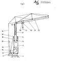
- FIG. 3 differs essentially from the embodiment of FIGS. 1 and 2 only in that the lifting rope 39 via a rope pulley 50 at the upper end of the outer tower piece 6, a rope pulley 51 at the lower end of the inner tower piece 21 and a rope pulley 52 runs at the upper end of the inner tower piece 21 to the rollers 53 of the trolley 20.
- the boom is opened with the inner tower piece retracted or intermediate positions of the inner tower piece, the rope pulley 51 is detached from the inner tower piece 21 and coupled as a bottom block 51 'of a pulley block to a rope 56 running over the rope pulleys 54, 55, the latter other end at point 57 is connected to the guy rope 34. Then, after the inner tower piece 21 has been partially extended and fixed relative to the outer tower piece 6, the boom can be opened via the lifting rope 39. After the boom has been opened, the rear guy cable 34 is fastened to the rotating platform 3 with a correspondingly shortened length.
- the outer support part of the jib can be swung up.
- the inner support part 24 can be swiveled up when the crane hook 43 is moved on the block by actuating the lifting winch 8.
- the pivoting movements of the inner and outer carrier parts can be superimposed on one another.
Landscapes
- Engineering & Computer Science (AREA)
- Mechanical Engineering (AREA)
- Structural Engineering (AREA)
- Transportation (AREA)
- Jib Cranes (AREA)
Priority Applications (1)
| Application Number | Priority Date | Filing Date | Title |
|---|---|---|---|
| AT84114818T ATE42942T1 (de) | 1984-01-13 | 1984-12-05 | Kran mit teleskopierbarem turm. |
Applications Claiming Priority (2)
| Application Number | Priority Date | Filing Date | Title |
|---|---|---|---|
| DE3401094 | 1984-01-13 | ||
| DE3401094A DE3401094C2 (de) | 1984-01-13 | 1984-01-13 | Kran mit teleskopierbarem Turm |
Publications (3)
| Publication Number | Publication Date |
|---|---|
| EP0150344A2 true EP0150344A2 (fr) | 1985-08-07 |
| EP0150344A3 EP0150344A3 (en) | 1987-09-09 |
| EP0150344B1 EP0150344B1 (fr) | 1989-05-10 |
Family
ID=6224943
Family Applications (1)
| Application Number | Title | Priority Date | Filing Date |
|---|---|---|---|
| EP84114818A Expired EP0150344B1 (fr) | 1984-01-13 | 1984-12-05 | Grue avec tour télescopique |
Country Status (3)
| Country | Link |
|---|---|
| EP (1) | EP0150344B1 (fr) |
| AT (1) | ATE42942T1 (fr) |
| DE (2) | DE3401094C2 (fr) |
Cited By (1)
| Publication number | Priority date | Publication date | Assignee | Title |
|---|---|---|---|---|
| DE3719986A1 (de) * | 1987-06-15 | 1988-12-29 | Liebherr Werk Biberach Gmbh | Turmdrehkran |
Families Citing this family (2)
| Publication number | Priority date | Publication date | Assignee | Title |
|---|---|---|---|---|
| DE3422146A1 (de) * | 1984-02-21 | 1985-08-22 | Liebherr-Werk Bischofshofen GmbH, Bischofshofen | Kran mit teleskopierbarem turm |
| CN101962156B (zh) * | 2010-10-18 | 2012-04-04 | 南京工业大学 | 一种可折叠快装塔机 |
Family Cites Families (10)
| Publication number | Priority date | Publication date | Assignee | Title |
|---|---|---|---|---|
| DE976018C (de) * | 1953-05-21 | 1963-01-17 | Hans Tax | Turmdrehkran mit einem um eine waagerechte Achse des Kranwagens aufrichtbaren Turm |
| AT294370B (de) * | 1969-10-22 | 1971-11-25 | Wetzel Kg | Turmdrehkran |
| FR2138254B2 (fr) * | 1971-05-21 | 1975-10-10 | Esteve Andre | |
| FR2236772A1 (en) * | 1973-07-03 | 1975-02-07 | Rock Sa | Tower crane erection system - has hoist rope reeved round pulley block attached to erection winch rope |
| FR2398017A1 (fr) * | 1977-07-22 | 1979-02-16 | Acme | Perfectionnements aux systemes pour le repliage ou le deploiement de la fleche articulee d'une grue a mat telescopique |
| FR2422581A1 (fr) * | 1978-04-10 | 1979-11-09 | Potain Sa | Systeme pour le depliage loin du sol de la fleche d'une grue telescopique |
| DE2944473A1 (de) * | 1979-11-03 | 1981-05-14 | Cadillon S.A., Charolles | Kran sowie verfahren zu seiner bedienung |
| DE3005984C2 (de) * | 1980-02-18 | 1985-04-11 | Pekazett Baumaschinen GmbH, 6660 Zweibrücken | Turmdrehkran |
| DE8009033U1 (de) * | 1980-04-01 | 1980-09-04 | Liebherr-Werk Bischofshofen Gmbh, Bischofshofen (Oesterreich) | Kran mit teleskopturm |
| DE3229949C1 (de) * | 1982-08-12 | 1983-11-17 | Peiner Hebe- Und Transportsysteme Gmbh, 5500 Trier | Turmkran |
-
1984
- 1984-01-13 DE DE3401094A patent/DE3401094C2/de not_active Expired
- 1984-12-05 EP EP84114818A patent/EP0150344B1/fr not_active Expired
- 1984-12-05 AT AT84114818T patent/ATE42942T1/de not_active IP Right Cessation
- 1984-12-05 DE DE8484114818T patent/DE3478102D1/de not_active Expired
Cited By (1)
| Publication number | Priority date | Publication date | Assignee | Title |
|---|---|---|---|---|
| DE3719986A1 (de) * | 1987-06-15 | 1988-12-29 | Liebherr Werk Biberach Gmbh | Turmdrehkran |
Also Published As
| Publication number | Publication date |
|---|---|
| DE3401094C2 (de) | 1986-12-18 |
| EP0150344A3 (en) | 1987-09-09 |
| DE3478102D1 (en) | 1989-06-15 |
| EP0150344B1 (fr) | 1989-05-10 |
| DE3401094A1 (de) | 1985-07-25 |
| ATE42942T1 (de) | 1989-05-15 |
Similar Documents
| Publication | Publication Date | Title |
|---|---|---|
| EP1894883B1 (fr) | Grue de véhicule | |
| EP0779236A1 (fr) | Grue mobile | |
| EP0132572B1 (fr) | Grue à tour télescopique | |
| DE9316113U1 (de) | Turmdrehkran | |
| EP0624542A2 (fr) | Grue à tour téléscopique | |
| DE3207443A1 (de) | Drehkran | |
| DE19730361A1 (de) | Fahrzeugkran | |
| EP0150344B1 (fr) | Grue avec tour télescopique | |
| DE3340845C1 (de) | Gittermastkran mit zerlegbarem Hauptausleger | |
| DE2300643A1 (de) | Fahrzeugkran | |
| EP0152562A2 (fr) | Grue à tour télescopique | |
| EP0296383A1 (fr) | Grue à tour tournante | |
| DE4221915A1 (de) | Untendrehender Turmdrehkran | |
| DE20314561U1 (de) | Kran | |
| DE8205723U1 (de) | Drehkran | |
| EP0997427B1 (fr) | Grue à tour pivotante | |
| DE2101842C (de) | Turmkran | |
| DE29916410U1 (de) | Gelenkig miteinander verbundene, im Querschnitt dreieckige Gitterträger | |
| EP1084983A1 (fr) | Grue à tour | |
| AT526450A2 (de) | Fahrzeugkran mit einem lösbaren Anbau-Oberwagen und Rüstverfahren hierzu | |
| DE1456454C (de) | Turmdrehkran | |
| DE2300579C3 (de) | Kran mit zusammenklappbarem Mast und Ausleger | |
| DE9214587U1 (de) | Arbeitsbühne | |
| DE1057307B (de) | Hochbaukran mit umlegbarem Turm und Nadelausleger | |
| DE9321390U1 (de) | Kran mit teleskopierbarem Turm |
Legal Events
| Date | Code | Title | Description |
|---|---|---|---|
| PUAI | Public reference made under article 153(3) epc to a published international application that has entered the european phase |
Free format text: ORIGINAL CODE: 0009012 |
|
| AK | Designated contracting states |
Designated state(s): AT BE CH DE FR GB IT LI NL |
|
| PUAL | Search report despatched |
Free format text: ORIGINAL CODE: 0009013 |
|
| AK | Designated contracting states |
Kind code of ref document: A3 Designated state(s): AT BE CH DE FR GB IT LI NL |
|
| 17P | Request for examination filed |
Effective date: 19871030 |
|
| 17Q | First examination report despatched |
Effective date: 19880413 |
|
| GRAA | (expected) grant |
Free format text: ORIGINAL CODE: 0009210 |
|
| AK | Designated contracting states |
Kind code of ref document: B1 Designated state(s): AT BE CH DE FR GB IT LI NL |
|
| PG25 | Lapsed in a contracting state [announced via postgrant information from national office to epo] |
Ref country code: NL Effective date: 19890510 Ref country code: IT Free format text: LAPSE BECAUSE OF FAILURE TO SUBMIT A TRANSLATION OF THE DESCRIPTION OR TO PAY THE FEE WITHIN THE PRESCRIBED TIME-LIMIT;WARNING: LAPSES OF ITALIAN PATENTS WITH EFFECTIVE DATE BEFORE 2007 MAY HAVE OCCURRED AT ANY TIME BEFORE 2007. THE CORRECT EFFECTIVE DATE MAY BE DIFFERENT FROM THE ONE RECORDED. Effective date: 19890510 Ref country code: GB Effective date: 19890510 Ref country code: BE Effective date: 19890510 |
|
| REF | Corresponds to: |
Ref document number: 42942 Country of ref document: AT Date of ref document: 19890515 Kind code of ref document: T |
|
| REF | Corresponds to: |
Ref document number: 3478102 Country of ref document: DE Date of ref document: 19890615 |
|
| ET | Fr: translation filed | ||
| NLV1 | Nl: lapsed or annulled due to failure to fulfill the requirements of art. 29p and 29m of the patents act | ||
| GBV | Gb: ep patent (uk) treated as always having been void in accordance with gb section 77(7)/1977 [no translation filed] | ||
| PG25 | Lapsed in a contracting state [announced via postgrant information from national office to epo] |
Ref country code: AT Effective date: 19891205 |
|
| PG25 | Lapsed in a contracting state [announced via postgrant information from national office to epo] |
Ref country code: LI Effective date: 19891231 Ref country code: CH Effective date: 19891231 |
|
| PLBE | No opposition filed within time limit |
Free format text: ORIGINAL CODE: 0009261 |
|
| STAA | Information on the status of an ep patent application or granted ep patent |
Free format text: STATUS: NO OPPOSITION FILED WITHIN TIME LIMIT |
|
| 26N | No opposition filed | ||
| REG | Reference to a national code |
Ref country code: CH Ref legal event code: PL |
|
| PGFP | Annual fee paid to national office [announced via postgrant information from national office to epo] |
Ref country code: FR Payment date: 19941208 Year of fee payment: 11 |
|
| PGFP | Annual fee paid to national office [announced via postgrant information from national office to epo] |
Ref country code: DE Payment date: 19950125 Year of fee payment: 11 |
|
| PG25 | Lapsed in a contracting state [announced via postgrant information from national office to epo] |
Ref country code: FR Effective date: 19960830 |
|
| PG25 | Lapsed in a contracting state [announced via postgrant information from national office to epo] |
Ref country code: DE Effective date: 19960903 |
|
| REG | Reference to a national code |
Ref country code: FR Ref legal event code: ST |