EP0150382B1 - Système de transmission d'informations - Google Patents
Système de transmission d'informations Download PDFInfo
- Publication number
- EP0150382B1 EP0150382B1 EP84115230A EP84115230A EP0150382B1 EP 0150382 B1 EP0150382 B1 EP 0150382B1 EP 84115230 A EP84115230 A EP 84115230A EP 84115230 A EP84115230 A EP 84115230A EP 0150382 B1 EP0150382 B1 EP 0150382B1
- Authority
- EP
- European Patent Office
- Prior art keywords
- response unit
- unit
- carrier signals
- information
- transmission system
- Prior art date
- Legal status (The legal status is an assumption and is not a legal conclusion. Google has not performed a legal analysis and makes no representation as to the accuracy of the status listed.)
- Expired - Lifetime
Links
- 230000004044 response Effects 0.000 claims abstract description 32
- 230000005540 biological transmission Effects 0.000 claims abstract description 21
- 239000000203 mixture Substances 0.000 claims abstract 6
- 238000000034 method Methods 0.000 claims description 5
- 238000011144 upstream manufacturing Methods 0.000 claims description 3
- 230000008520 organization Effects 0.000 description 2
- 239000000969 carrier Substances 0.000 description 1
- 230000001419 dependent effect Effects 0.000 description 1
- 230000005669 field effect Effects 0.000 description 1
- 238000009434 installation Methods 0.000 description 1
- 230000002452 interceptive effect Effects 0.000 description 1
- 230000000007 visual effect Effects 0.000 description 1
Images
Classifications
-
- B—PERFORMING OPERATIONS; TRANSPORTING
- B61—RAILWAYS
- B61L—GUIDING RAILWAY TRAFFIC; ENSURING THE SAFETY OF RAILWAY TRAFFIC
- B61L25/00—Recording or indicating positions or identities of vehicles or trains or setting of track apparatus
- B61L25/02—Indicating or recording positions or identities of vehicles or trains
- B61L25/04—Indicating or recording train identities
- B61L25/045—Indicating or recording train identities using reradiating tags
-
- B—PERFORMING OPERATIONS; TRANSPORTING
- B61—RAILWAYS
- B61L—GUIDING RAILWAY TRAFFIC; ENSURING THE SAFETY OF RAILWAY TRAFFIC
- B61L25/00—Recording or indicating positions or identities of vehicles or trains or setting of track apparatus
- B61L25/02—Indicating or recording positions or identities of vehicles or trains
- B61L25/04—Indicating or recording train identities
-
- G—PHYSICS
- G01—MEASURING; TESTING
- G01S—RADIO DIRECTION-FINDING; RADIO NAVIGATION; DETERMINING DISTANCE OR VELOCITY BY USE OF RADIO WAVES; LOCATING OR PRESENCE-DETECTING BY USE OF THE REFLECTION OR RERADIATION OF RADIO WAVES; ANALOGOUS ARRANGEMENTS USING OTHER WAVES
- G01S13/00—Systems using the reflection or reradiation of radio waves, e.g. radar systems; Analogous systems using reflection or reradiation of waves whose nature or wavelength is irrelevant or unspecified
- G01S13/74—Systems using reradiation of radio waves, e.g. secondary radar systems; Analogous systems
- G01S13/75—Systems using reradiation of radio waves, e.g. secondary radar systems; Analogous systems using transponders powered from received waves, e.g. using passive transponders, or using passive reflectors
- G01S13/751—Systems using reradiation of radio waves, e.g. secondary radar systems; Analogous systems using transponders powered from received waves, e.g. using passive transponders, or using passive reflectors wherein the responder or reflector radiates a coded signal
- G01S13/758—Systems using reradiation of radio waves, e.g. secondary radar systems; Analogous systems using transponders powered from received waves, e.g. using passive transponders, or using passive reflectors wherein the responder or reflector radiates a coded signal using a signal generator powered by the interrogation signal
-
- G—PHYSICS
- G08—SIGNALLING
- G08G—TRAFFIC CONTROL SYSTEMS
- G08G1/00—Traffic control systems for road vehicles
- G08G1/01—Detecting movement of traffic to be counted or controlled
- G08G1/017—Detecting movement of traffic to be counted or controlled identifying vehicles
Definitions
- the present invention relates to an information transmission system consisting of an interrogation unit and an answering unit, wherein the interrogation unit emits carrier signals which the answering unit receives as it passes through the interrogation unit, mixes them in frequency and, after modulation, returns the mixed product to the information stored in the answering unit Sends query unit that receives and demodulates the modulated mixed product.
- Such an information system can e.g. are used to transmit information, such as distance information or maximum permissible speeds, from a track section to trains.
- a response unit is attached to each wagon, in which all of the data relevant to the wagons are stored.
- a query unit is permanently installed on the rail line and transmits the data read out from the response units to a central computer.
- the central computer which knows the sequence of the wagons and their destination stations, can now control the switches accordingly so that the wagons are lined up correctly.
- this information transmission system can e.g. can also be used to regulate road traffic.
- the vehicles would be equipped with query units that read information about location, traffic density, etc. from response units installed on the streets as they drive past.
- the carrier unit sends two carrier signals to the response unit.
- these two carrier signals result in a mixed product which is suitable for modulation with the information and whose frequency distance from the two carrier signals is very large.
- the frequencies of the two carrier signals and those of the mixed product do not fall within the transmission frequency range of a single waveguide because of their too large distances, which due to its high efficiency in power transmission is expedient, e.g. in the form of a horn, is used as an antenna on the part of the interrogation and response unit.
- a reception antenna and, in addition, a separate transmission antenna would therefore have to be provided on each side.
- two antennas make the response unit, which should be very flexible to use on any moving objects, unwieldy.
- the invention is based on the object of specifying an information transmission system of the type mentioned in the introduction, in which, in particular, the response unit is implemented with as little circuit complexity as possible and can be handled very flexibly due to a compact design.
- this object is achieved in that the interrogation unit emits at least three carrier signals which are in the transmission frequency band of a waveguide, and in that a mixer in the response unit forms a mixed product composed of all these carrier signals.
- the response unit transmits several carriers of different frequencies, with which the converter is fed in the response device, no separate oscillator circuit is required to supply the converter with a carrier signal.
- the response unit It is also advantageous to use the carrier signals for energy supply, the response unit. It then manages without its own operating supply and is not dependent on an energy source to be arranged at its installation location.
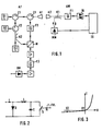
- the information transmission system shown in FIG. 1 consists of an interrogation unit AF and an answering unit AW.
- three generators G1, G2 and G3 generating the carrier signals with the frequencies f i , f 2 and f 3 are connected to an antenna A1 via three circulators Z1, Z2 and Z3. This antenna simultaneously emits the three carrier signals.
- the frequencies f i , f 2 , f 3 of the three carrier signals are selected such that they fall within the transmission frequency range of a waveguide which serves as antenna A1 in the form of a horn.
- the horn antenna A2 of the response unit AW has the same transmission frequency range as the horn antenna A1, which receives the three carrier signals of the frequency f 1 , f 2 and f 3 as it passes through the interrogation unit AF.
- a coupler K1 behind the antenna A2 in the response unit decouples a larger proportion of energy ( ⁇ 90%) from the received carrier signals, which is then rectified by a rectifier GL and supplied to the circuit elements in an information memory IS as operating energy.
- a filter F1 connected upstream of the rectifier suppresses undesired intermodulation products which arise on the rectifier diodes.
- the remaining energy component of the three carrier signals is sent to a mixer MM, which consists of all Carrier signals of the frequencies f i , f 2 , f 3 the mixed product with the frequencies and forms. These frequencies of the mixed product are very close to the frequencies of the three carrier signals, so that they too, like the carrier frequencies, lie in the transmission frequency range of the horn antennas A1 and A2. With a single horn antenna A1 of the interrogation unit AF or a horn antenna A2 of the response unit AW, the three carrier signals can be transmitted or received as well as their mixed product can be received or transmitted.
- This example shows that the frequencies of the mixed product are very close to the frequencies of the three carrier signals.
- the frequency f i * of the mixed product is expediently chosen, which lies below the three carrier frequencies f i , f 2 , f 3 , because this frequency can be selected more easily in terms of filter technology.
- the filter F1 can be designed as a high-pass filter upstream of the rectifier GL.
- a high-pass filter can namely simply be realized by a waveguide operated below its cut-off frequency, which is attached to the throat of the horn antenna A2. This high-pass filter ensures that an intermodulation product of frequency f 1 * generated by the rectifier GL does not reach antenna A2 and is emitted. This is because the modulation product of frequency f, which is modulated with the information stored in the information memory IS and is formed in the mixer MM, is to be transmitted.
- the information store IS is e.g. equipped with ERPROM's or RAM's.
- the clock control and addressing circuits necessary for the memory elements and familiar to the person skilled in the art will not be discussed in more detail here.
- the information that is to be stored in the memory can be supplied to the response unit by radio from a central unit. It would also be conceivable to manually enter the information into the memory using a keyboard installed on the response unit. In addition, the information stored in the memory could be made visible on a visual display on the responder. If, after a short settling time, the bias voltage derived from the carrier signals is applied to the information memory, the reading process of the memory begins. With the information signal, which has the level states "0" and "1" as a binary signal, the mixed product generated in the mixer MM is amplitude-modulated and the modulated mixed product is transmitted to the interrogation unit AF via the antenna A2.
- a circuit which combines a mixer and an amplitude modulator in a very simple manner contains a component with a non-linear characteristic, a diode D, to which the three carrier signals t are supplied.
- the inductance L and the capacitance C, with which the diode D is connected, serve to separate the direct bias of the diode from the high-frequency signals.
- a switch S connected to the mixer which suitably is an electronic switch, e.g. is a field effect transistor is controlled by the information signal from the information memory IS serving as modulation signal m.
- the opening or closing of the switch S corresponding to the level "0" or "1" of the modulation signal m causes an operating point shift on the non-linear characteristic curve of the mixer diode D.
- the advantage of the mixer and modulator circuit described is that it can be operated without impressing its own diode bias.
- the modulated mixed product received by the interrogation unit AF is coupled by the circulator Z3 into a demodulation branch which contains a filter F2, a mixer M, a filter F3 and an amplitude demodulator DM.
- the filter F2 only lets the modulated mixed product through to the subsequent mixer M and suppresses the three carrier signals, which are also coupled into the demodulation branch because of a finite decoupling of the circulators. These three carrier signals would otherwise cause interfering mixed products at the mixer M.
- the mixer M converts the modulated mixed product into the intermediate frequency level with the aid of an oscillator signal, for example the frequency f 3 , which is decoupled from a coupler K2 behind the generator G3.
- the filter F3 in the intermediate frequency level selects one of the modulated signals from that at the mixer M resulting mixed product out. This one signal reaches the demodulator DM, which uses it to recover the information from the response unit AW.
Landscapes
- Engineering & Computer Science (AREA)
- Radar, Positioning & Navigation (AREA)
- Remote Sensing (AREA)
- Mechanical Engineering (AREA)
- Physics & Mathematics (AREA)
- General Physics & Mathematics (AREA)
- Computer Networks & Wireless Communication (AREA)
- Radar Systems Or Details Thereof (AREA)
- Circuits Of Receivers In General (AREA)
- Exchange Systems With Centralized Control (AREA)
- Preparation Of Compounds By Using Micro-Organisms (AREA)
- Low-Molecular Organic Synthesis Reactions Using Catalysts (AREA)
Claims (4)
Priority Applications (1)
| Application Number | Priority Date | Filing Date | Title |
|---|---|---|---|
| AT84115230T ATE53548T1 (de) | 1984-01-18 | 1984-12-12 | Informationsuebertragungssystem. |
Applications Claiming Priority (2)
| Application Number | Priority Date | Filing Date | Title |
|---|---|---|---|
| DE19843401517 DE3401517A1 (de) | 1984-01-18 | 1984-01-18 | Informationsuebertragungssystem |
| DE3401517 | 1984-01-18 |
Publications (3)
| Publication Number | Publication Date |
|---|---|
| EP0150382A2 EP0150382A2 (fr) | 1985-08-07 |
| EP0150382A3 EP0150382A3 (en) | 1985-10-02 |
| EP0150382B1 true EP0150382B1 (fr) | 1990-06-13 |
Family
ID=6225208
Family Applications (1)
| Application Number | Title | Priority Date | Filing Date |
|---|---|---|---|
| EP84115230A Expired - Lifetime EP0150382B1 (fr) | 1984-01-18 | 1984-12-12 | Système de transmission d'informations |
Country Status (3)
| Country | Link |
|---|---|
| EP (1) | EP0150382B1 (fr) |
| AT (1) | ATE53548T1 (fr) |
| DE (2) | DE3401517A1 (fr) |
Cited By (1)
| Publication number | Priority date | Publication date | Assignee | Title |
|---|---|---|---|---|
| CN102963394A (zh) * | 2012-12-10 | 2013-03-13 | 北京交大思诺科技有限公司 | 频分多路容量倍增型车载接收设备与应答器系统 |
Families Citing this family (2)
| Publication number | Priority date | Publication date | Assignee | Title |
|---|---|---|---|---|
| EP0270274A3 (fr) * | 1986-12-05 | 1990-01-24 | Meridian Micro-Systems Limited | Répondeur et interrogateur |
| EP0638871A3 (fr) * | 1993-08-05 | 1995-12-13 | Sel Alcatel Ag | Dispositif de reconnaissance et de lecture de transpondeurs mobiles relatif à ce dispositif. |
Family Cites Families (3)
| Publication number | Priority date | Publication date | Assignee | Title |
|---|---|---|---|---|
| DE3015437C2 (de) * | 1980-04-22 | 1982-10-28 | Siemens AG, 1000 Berlin und 8000 München | Duplex-Sende-Empfangseinrichtung |
| DE3027981A1 (de) * | 1980-07-24 | 1982-02-25 | Licentia Patent-Verwaltungs-Gmbh, 6000 Frankfurt | Identifikationssystem bestehend aus einem abfragegeraet und einem antwortgeraet |
| EP0111591A1 (fr) * | 1982-12-23 | 1984-06-27 | ANT Nachrichtentechnik GmbH | Dispositif pour la transmission d'information entre objets en mouvement passant mutuellement |
-
1984
- 1984-01-18 DE DE19843401517 patent/DE3401517A1/de not_active Withdrawn
- 1984-12-12 EP EP84115230A patent/EP0150382B1/fr not_active Expired - Lifetime
- 1984-12-12 AT AT84115230T patent/ATE53548T1/de not_active IP Right Cessation
- 1984-12-12 DE DE8484115230T patent/DE3482462D1/de not_active Expired - Fee Related
Cited By (1)
| Publication number | Priority date | Publication date | Assignee | Title |
|---|---|---|---|---|
| CN102963394A (zh) * | 2012-12-10 | 2013-03-13 | 北京交大思诺科技有限公司 | 频分多路容量倍增型车载接收设备与应答器系统 |
Also Published As
| Publication number | Publication date |
|---|---|
| EP0150382A2 (fr) | 1985-08-07 |
| DE3482462D1 (de) | 1990-07-19 |
| DE3401517A1 (de) | 1985-07-25 |
| EP0150382A3 (en) | 1985-10-02 |
| ATE53548T1 (de) | 1990-06-15 |
Similar Documents
| Publication | Publication Date | Title |
|---|---|---|
| EP0111592B1 (fr) | Système automatique d'information pour objets mobiles | |
| DE3886215T2 (de) | Schiene/zug-nachrichtensysteme. | |
| DE2612996C2 (fr) | ||
| DE2744212C2 (de) | Duplex-Sende-Empfangseinrichtung | |
| EP0519361B1 (fr) | Dispositif de radar à onde continue, usable additionellement comme transmetteur d'informations | |
| EP0150382B1 (fr) | Système de transmission d'informations | |
| DE3855803T2 (de) | Identifizierungsbake bei der Durchfahrt eines Fahrzeuges in einem bestimmten Punkt | |
| DE2615797A1 (de) | Einrichtung zum uebermitteln von informationen | |
| EP0556221B1 (fr) | Procede pour la tranmission d'informations routieres par radiofrequence et dispositifs correspondants | |
| EP0793191A1 (fr) | Appareil pour la programmation d'une station terrestre | |
| DE2453647A1 (de) | Informationsuebertragungssystem fuer drahtlose uebertragung | |
| DE3010264C2 (de) | Verfahren zur Datenübertragung mittels Mikrowellen und Anordnung zur Durchführung des Verfahrens | |
| EP0706144A2 (fr) | Dispositif pour la lecture sélective de transpondeurs | |
| DE3027981C2 (fr) | ||
| EP0111591A1 (fr) | Dispositif pour la transmission d'information entre objets en mouvement passant mutuellement | |
| DE936339C (de) | Anordnung zur UEberwachung von Fahrzeugen, insbesondere fuer die Zugschlussmeldung von Eisenbahnzuegen | |
| DE2151105B2 (de) | Anordnung zum Identifizieren von Gegenständen | |
| DE2061876A1 (de) | System zur Funk-Übertragung von Nachrichten, insbesondere von Verkehrsnachrichten, an mit Empfängern ausgerüstete Fahrzeuge | |
| DE2709620C2 (de) | Anordnung zum selbsttätigen Erkennen längs einer Fahrbahn angeordneter Standortzeichen | |
| DE3509965A1 (de) | Verfahren zur einstellung von verkehrsfunk-empfaengern | |
| DE2707091C3 (de) | Funksystem für sehr kurze elektromagnetische Wellen zur ortsselektiven Übertragung ortsspezifischer Informationen | |
| EP0199162A2 (fr) | Système de transmission d'informations | |
| EP0023605A1 (fr) | Système de radiocommunication | |
| DE4237677C1 (de) | Verfahren zur Übertragung von Informationen an Verkehrsteilnehmer | |
| DE19540928A1 (de) | Positionierverfahren |
Legal Events
| Date | Code | Title | Description |
|---|---|---|---|
| PUAI | Public reference made under article 153(3) epc to a published international application that has entered the european phase |
Free format text: ORIGINAL CODE: 0009012 |
|
| PUAL | Search report despatched |
Free format text: ORIGINAL CODE: 0009013 |
|
| AK | Designated contracting states |
Designated state(s): AT CH DE LI NL SE |
|
| AK | Designated contracting states |
Designated state(s): AT CH DE LI NL SE |
|
| 17P | Request for examination filed |
Effective date: 19851125 |
|
| 17Q | First examination report despatched |
Effective date: 19880912 |
|
| GRAA | (expected) grant |
Free format text: ORIGINAL CODE: 0009210 |
|
| AK | Designated contracting states |
Kind code of ref document: B1 Designated state(s): AT CH DE LI NL SE |
|
| REF | Corresponds to: |
Ref document number: 53548 Country of ref document: AT Date of ref document: 19900615 Kind code of ref document: T |
|
| REF | Corresponds to: |
Ref document number: 3482462 Country of ref document: DE Date of ref document: 19900719 |
|
| PLBE | No opposition filed within time limit |
Free format text: ORIGINAL CODE: 0009261 |
|
| STAA | Information on the status of an ep patent application or granted ep patent |
Free format text: STATUS: NO OPPOSITION FILED WITHIN TIME LIMIT |
|
| 26N | No opposition filed | ||
| PGFP | Annual fee paid to national office [announced via postgrant information from national office to epo] |
Ref country code: AT Payment date: 19941216 Year of fee payment: 11 |
|
| PGFP | Annual fee paid to national office [announced via postgrant information from national office to epo] |
Ref country code: SE Payment date: 19941219 Year of fee payment: 11 |
|
| PGFP | Annual fee paid to national office [announced via postgrant information from national office to epo] |
Ref country code: DE Payment date: 19941222 Year of fee payment: 11 |
|
| PGFP | Annual fee paid to national office [announced via postgrant information from national office to epo] |
Ref country code: NL Payment date: 19941231 Year of fee payment: 11 |
|
| PGFP | Annual fee paid to national office [announced via postgrant information from national office to epo] |
Ref country code: CH Payment date: 19950118 Year of fee payment: 11 |
|
| EAL | Se: european patent in force in sweden |
Ref document number: 84115230.9 |
|
| PG25 | Lapsed in a contracting state [announced via postgrant information from national office to epo] |
Ref country code: AT Effective date: 19951212 |
|
| PG25 | Lapsed in a contracting state [announced via postgrant information from national office to epo] |
Ref country code: SE Effective date: 19951213 |
|
| PG25 | Lapsed in a contracting state [announced via postgrant information from national office to epo] |
Ref country code: LI Effective date: 19951231 Ref country code: CH Effective date: 19951231 |
|
| PG25 | Lapsed in a contracting state [announced via postgrant information from national office to epo] |
Ref country code: NL Effective date: 19960701 |
|
| REG | Reference to a national code |
Ref country code: CH Ref legal event code: PL |
|
| NLV4 | Nl: lapsed or anulled due to non-payment of the annual fee |
Effective date: 19960701 |
|
| PG25 | Lapsed in a contracting state [announced via postgrant information from national office to epo] |
Ref country code: DE Effective date: 19960903 |