EP0150541A2 - Tomographe à résonance magnétique nucléaire - Google Patents
Tomographe à résonance magnétique nucléaire Download PDFInfo
- Publication number
- EP0150541A2 EP0150541A2 EP84201939A EP84201939A EP0150541A2 EP 0150541 A2 EP0150541 A2 EP 0150541A2 EP 84201939 A EP84201939 A EP 84201939A EP 84201939 A EP84201939 A EP 84201939A EP 0150541 A2 EP0150541 A2 EP 0150541A2
- Authority
- EP
- European Patent Office
- Prior art keywords
- coil
- magnetic field
- current
- coil arrangements
- arrangements
- Prior art date
- Legal status (The legal status is an assumption and is not a legal conclusion. Google has not performed a legal analysis and makes no representation as to the accuracy of the status listed.)
- Granted
Links
Images


Classifications
-
- G—PHYSICS
- G01—MEASURING; TESTING
- G01R—MEASURING ELECTRIC VARIABLES; MEASURING MAGNETIC VARIABLES
- G01R33/00—Arrangements or instruments for measuring magnetic variables
- G01R33/20—Arrangements or instruments for measuring magnetic variables involving magnetic resonance
- G01R33/28—Details of apparatus provided for in groups G01R33/44 - G01R33/64
- G01R33/38—Systems for generation, homogenisation or stabilisation of the main or gradient magnetic field
- G01R33/385—Systems for generation, homogenisation or stabilisation of the main or gradient magnetic field using gradient magnetic field coils
Definitions
- the invention relates to a magnetic resonance tomograph with an arrangement for generating a homogeneous static magnetic field and with three coil arrangements through which currents which vary in time flow and which are used to generate additional magnetic fields which run in the direction of the static magnetic field and which change spatially linear in three mutually perpendicular directions, and with a high-frequency coil for generating a high-frequency magnetic field perpendicular to the direction of the main field.
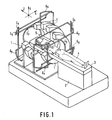
- the magnetic resonance tomograph comprises an arrangement for generating a strong homogeneous static magnetic field which runs in the z direction of an xyz coordinate system.
- This arrangement consists of four mutually concentric annular coils 1, the central axis of which extends in the z direction.
- the magnetic field is homogeneous over a relatively large area - the examination area - and has a flux density between 0.1 T and 2 T, the higher flux densities generally having to be generated with the aid of a superconducting coil arrangement.
- a patient 4 located on a patient positioning table 2 with a table top 3 that can be moved in the z direction is brought into this examination area.
- the magnetic resonance tomograph has three coil arrangements for the generation of those running in the z direction Magnetic fields that change spatially linear in the x, y and z directions. These coil arrangements are generally referred to in the literature as "gradient coils".
- the coil arrangement for generating a magnetic field running in the z direction and linearly decreasing in this direction consists of at least two identical coils Gz offset from one another in the z direction and arranged symmetrically to the coils 1, between which a coil Gz running and in this direction A magnetic field that changes linearly with the location is generated when a current flows through these coils in opposite directions.
- the coil arrangement for generating a magnetic field which also runs in the z direction, but which changes spatially linearly in the x direction consists of the four identical coils Gx. These approximately rectangular coils are arranged on the circumference of a circular cylinder, the center line of which is parallel to the y-axis and penetrates the center of the rings 1 and thus the examination area.
- the four coils Gx are flowed through by currents of the same size, which are directed so that in adjacent coils the parts facing the other coil and extending in the y direction are flowed through in the same direction.
- the coil arrangement for generating a magnetic field running in the z direction which changes linearly with the location in the y direction, has the same structure as the coil arrangement Gx, but is rotated through 90 ° with respect to this. Ie this coil arrangement also consists of four rectangular coils arranged on the circumference of a circular cylinder, the central axis of this circular cylinder, however, running parallel to the x-axis through the center of the examination area. - That of the coil arrangements Gx and Gy generated magnetic field has zero flux density in the axis of symmetry running in the z direction.
- a high-frequency coil 5 which generates a homogeneous high-frequency magnetic field in the examination area, the frequency of which corresponds to the Larmor frequency with which the nuclear spins generated in the examination area precess around the z-axis.
- such an MRI scanner has a large number of imaging options.
- nuclear spins can be excited in a volume of the body to be examined in the examination area, which, with suitable excitation of the three coil arrangements Gx, Gy, Gz, allows the reconstruction of the nuclear spin distribution in this volume.
- three-dimensional imaging methods are very time-consuming and have therefore not been able to establish themselves in practice.
- Two-dimensional imaging methods are used much more frequently, in which the nuclear spins are excited in only one layer of the object to be examined.
- the coils Gz are excited by a current during the excitation of the nuclear spins by the high-frequency coil 5, so that the magnetic field generated by the coils 1 and Gz changes linearly from one coil Gz to the other.
- the nuclear spins in that layer whose Larmor frequency - the Larmor frequency is known to be proportional to the magnetic field strength - corresponds to the frequency of the high-frequency field.
- the coils Gx and Gy are then excited simultaneously or in succession, so that the magnetic field within the layer changes in the x and y directions. This makes the phases and the amplitude of the resonance signal induced in the coil 5 after the excitation influences that the nuclear spin distribution in the excited layer can be reconstructed.
- FIG. 2a shows the spatial profile of the magnetic field strength in an x-y plane.
- the horizontal straight lines illustrate the field of the coils Gy, the magnetic field strength between any pairs of adjacent straight lines changing by the same amount.
- An improvement in the resolution would require, among other things, an increase in the measuring times, which are already relatively long anyway, or else an increase in the magnetic field gradient, which would result in an increase in the bandwidth of the received signal, as a result of which the signal to noise ratio would in turn deteriorate.
- the object of the present invention is to design a magnetic resonance tomograph of the type mentioned at the outset in such a way that the resolving power is improved in part of the examination area.
- At least one further coil arrangement is present for generating a magnetic field which also extends in the direction of the main field and which changes spatially non-linearly, and in that the further coil arrangement can be connected to a current source which supplies a current i which is the condition is sufficient, where a, b, c are constants and i1, i2, i3 the currents through the three coil arrangements.
- the invention takes a different approach and uses (at least) one coil arrangement, the magnetic field of which changes spatially non-linearly, the magnetic field gradient of which depends on the position in space.
- the resolving power is spatially constant in the known magnetic resonance tomographs, in the invention it changes according to the gradient of the magnetic field, i.e. in an area where the gradient of the magnetic field is large, the resolving power is also large, and in an area with a small gradient of the magnetic field, the resolving power is small.
- the extent to which the gradient of the magnetic field changes spatially can be determined separately with the constants a, b and c for each examination. For example, if all three constants are zero, the magnetic field generated by the further coil arrangement is also zero, so that only the magnetic fields generated by the three coil arrangements determine the imaging method with a constant gradient.
- the opposite extreme case arises when the current i1, i2 or i3 flows through the further coil arrangement with spatially constant gradients instead of through the associated coil arrangement. In this case, one of the coefficients a, b or c would be infinite or very large.
- a preferred development of the invention provides that at least two coil arrangements for generating the static magnetic field parallel magnetic fields are provided, which, however, change spatially non-linearly in the same direction in different ways, and that the currents through these coils have the same time profile but an adjustable amplitude.
- the spatial position for example of the maximum of the magnetic field gradient, can be adapted to predetermined requirements. This means that the position of the part of the examination area in which the resolution is particularly large can be varied according to the respective requirements.
- This embodiment of the invention is - like the invention itself - basically applicable to three-dimensional imaging methods, but in particular also two-dimensional imaging methods.
- the current for the coil arrangements Gx, Gy, Gz is supplied by current sources 6, 7 and 8, which are controlled by a central control unit 9 (FIG. 4). This controls also a current source arrangement 10 for generating direct currents for the coils 1, which generate the static magnetic field running in the z direction.
- a modulator 11 generates a carrier oscillation, which is supplied to the high-frequency coil 5 via a power amplifier 12, the frequency of the modulated oscillation and the size of the magnetic field generated by the coils 1 being coordinated with one another in such a way that 4 nuclear magnetic resonance is excited in a layer of the examined body .
- the signals induced in the coil 5 following this excitation are fed via an amplifier 13 to a phase-sensitive demodulator, the output signal of which is converted by a digital-analog converter 15 into a digital data word and fed to a reconstruction unit 16.
- This determines the spatial distribution of the nuclear spins in the excited layer from the supplied data according to a predetermined algorithm, and this distribution is displayed, for example, by means of a monitor 17. To the extent described so far, this arrangement is also known.
- the coils Gx2 and Gy2 generate a magnetic field which is directed parallel to the z-axis and whose strength is in x or.
- the y direction changes quadratically with the location, the magnetic field strength being zero in the axis of symmetry parallel to the z axis.
- the coils Gx3 and Gy3 generate a magnetic field running in the z direction, the field strength of which changes in the x and y direction with the third power of the location.
- the current sources 6, 61 and 62 are controlled by the central control unit 9 such that the current through the coils Gx, Gx2 and Gx3 has the same time profile, but a different - adjustable - amplitude.
- This goal can be achieved with the aid of three multiplier stages 63, 64, 65, the outputs of which are connected to the control inputs of the current sources 6, 61 and 62, respectively, and in which the signal of a function generator 66 is multiplied by factors generated by the control unit, which are the Represent the weight with which the field of the respective coil Gx, Gx2 or Gx3 is effective.
- all the coil arrangements Gx, Gx2 and Gx3 thus carry currents with the same profile, but the amplitudes of which can be set by the central control unit 9.
- control inputs of the coil arrangements Gy, Gy2 and Gy3 are connected to outputs of the multiplier stages 73, 74 and 75, in which the one Function generator 76 generated output signal determining the time profile of all three currents is multiplied by the weighting factors determined by the central control unit 9, so that the currents through these coils also have the same time profile but a different amplitude.
- the factors for the multiplication stages 64, 65 and 74 and 75 are chosen such that the currents of the current sources 61, 62 and 71 and 72 become zero, there is no difference compared to the magnetic resonance scanner previously explained with reference to FIG. 1.
- the magnetic fields generated by the gradient coil arrangements Gx, Gy have the field strength profile shown in FIG. 2 and a checkerboard-like nuclear spin distribution in the object under investigation is shown in FIG. 2b.
- the currents generated by the current sources 61, 62 and 71, 72 are different from zero, the result is a different picture.
- the magnetic field strength then no longer changes linearly in the xy plane and FIG. 3a then applies, the locations of the same magnetic field strength being connected to one another in a xy plane by a line (straight line) and any two adjacent lines each one certain field strength difference (assuming that the currents through the coils Gy, Gy2 and Gy3 are switched off when the currents flow through the coils Gx, Gx2 and Gx3 - and vice versa).
- the spatial distance between two adjacent lines is large on the outside and small on the outside in both the x and y directions, ie the gradient of the magnetic field strength has its maximum in the center.
- One examines with a magnet that is variable in the x and y direction as shown in FIG. 3a fields an object with a chessboard-like distributed nuclear spin density and if one reconstructs the nuclear spin density distribution in the examined plane from the signals induced in the coil 5, the distribution shown in FIG. 3b is obtained as a result.
- FIG. 2b it can be seen that the structure in the center is reproduced larger, while the structures on the edge are reproduced smaller.
- the geometrical distortion of the reconstructed nuclear spin density distribution compared to the actual distribution can optionally be eliminated again by changing the reconstruction algorithm. Because the amplitude of the currents through the coil arrangements Gx2 and Gx3 or Gy2 and Gy3 is known, the extent of the geometric distortion is also fixed, so that the reconstruction algorithm can be changed so that these distortions are eliminated. Instead of FIG. 3b, a reconstruction would then result that again corresponds to a checkerboard-like distribution. In contrast to FIG. 2b, the information density, ie the spatial resolution in the center would be greater than at the edge, ie details in the center would be shown more sharply than those at the edge.
- the current through the coil arrangements Gx and Gy can be made zero, while the current through at least one of the coil arrangements Gx2 and Gx3 or Gy2 and Gy3 is different from zero.
- the gradient field in the x and y directions would only change nonlinearly.
- coil arrangements in which the magnetic field strength changes square or cubic in the x or y direction
- coil arrangements can also be used in which the magnetic field strength changes in a non-linear manner with the location. Even then, the position of the gradient maxima could be changed by changing the combination of currents supplied to these coil arrangements.
- the coils Gx2 and Gx3 are flowed through by a current which only depends on the current flowing through the coil Gx, while the coils Gy2 and Gy3 are flowed through by a current which has the same time profile like the current through the coil Gy, but is independent of the current through the coil Gx.
- a different set of coefficients a, b, c can apply to each of the coils.
- the interpretation of the distorted image (see Fig. 3b) or its subsequent equalization makes it easier if the currents through the coils with a spatially non-linearly changing magnetic field (e.g. through Gx2, Gx3) have the same time profile as the current through the coil (Gx), whose magnetic field changes its field strength in the same direction - albeit spatially linear.
- a spatially non-linearly changing magnetic field e.g. through Gx2, Gx3
Landscapes
- Physics & Mathematics (AREA)
- Condensed Matter Physics & Semiconductors (AREA)
- General Physics & Mathematics (AREA)
- Magnetic Resonance Imaging Apparatus (AREA)
Applications Claiming Priority (2)
| Application Number | Priority Date | Filing Date | Title |
|---|---|---|---|
| DE3400861 | 1984-01-12 | ||
| DE19843400861 DE3400861A1 (de) | 1984-01-12 | 1984-01-12 | Kernspintomograph |
Publications (3)
| Publication Number | Publication Date |
|---|---|
| EP0150541A2 true EP0150541A2 (fr) | 1985-08-07 |
| EP0150541A3 EP0150541A3 (en) | 1987-04-01 |
| EP0150541B1 EP0150541B1 (fr) | 1989-11-23 |
Family
ID=6224791
Family Applications (1)
| Application Number | Title | Priority Date | Filing Date |
|---|---|---|---|
| EP84201939A Expired EP0150541B1 (fr) | 1984-01-12 | 1984-12-24 | Tomographe à résonance magnétique nucléaire |
Country Status (6)
| Country | Link |
|---|---|
| US (1) | US4644277A (fr) |
| EP (1) | EP0150541B1 (fr) |
| JP (1) | JPS60179645A (fr) |
| CA (1) | CA1232014A (fr) |
| DE (2) | DE3400861A1 (fr) |
| IL (1) | IL74029A (fr) |
Cited By (2)
| Publication number | Priority date | Publication date | Assignee | Title |
|---|---|---|---|---|
| DE3902479A1 (de) * | 1988-01-29 | 1989-08-10 | Toshiba Kawasaki Kk | Verfahren und vorrichtung zum abbilden von magnetischer kernresonanz |
| EP0405521A3 (en) * | 1989-06-29 | 1991-07-31 | Kabushiki Kaisha Toshiba | Method and apparatus of nuclear magnetic resonance imaging with optimized gradient magnetic field power source |
Families Citing this family (9)
| Publication number | Priority date | Publication date | Assignee | Title |
|---|---|---|---|---|
| ES2058714T3 (es) * | 1987-06-23 | 1994-11-01 | Nycomed Innovation Ab | Mejoras introducidas en formacion de imagenes por resonancia magnetica. |
| JPH01110354A (ja) * | 1987-10-26 | 1989-04-27 | Toshiba Corp | 磁気共鳴イメージング装置 |
| JP2646627B2 (ja) * | 1988-03-08 | 1997-08-27 | 株式会社日立製作所 | 核磁気共鳴を用いた検査装置 |
| JP2678252B2 (ja) * | 1992-08-28 | 1997-11-17 | エスビー食品株式会社 | キャップ開閉装置 |
| DE4309958C1 (de) * | 1993-03-26 | 1994-09-29 | Markus Von Dr Kienlin | Verfahren und Vorrichtung zur ortsauflösenden Magnetresonanzuntersuchung eines Meßobjekts |
| DE19616388A1 (de) * | 1996-04-24 | 1997-11-06 | Siemens Ag | Pulssequenz zur Selektion mehrerer Schichten in einem Kernspintomographiegerät |
| JP2002528148A (ja) | 1998-10-20 | 2002-09-03 | コーニンクレッカ フィリップス エレクトロニクス エヌ ヴィ | 補正コイルを有する傾斜コイル系を含む磁気共鳴撮像装置 |
| US6313630B1 (en) * | 1999-08-25 | 2001-11-06 | Ge Medical Systems Global Technology Company Llc | Modular gradient system for MRI system |
| DE19955117C2 (de) * | 1999-11-16 | 2001-09-27 | Siemens Ag | Verfahren zum Betrieb eines Magnetresonanztomographiegeräts |
Family Cites Families (3)
| Publication number | Priority date | Publication date | Assignee | Title |
|---|---|---|---|---|
| GB2070254B (en) * | 1980-01-21 | 1984-10-17 | Oxford Instr Group Ltd | Nuclear magnetic resonance apparatus and methods |
| US4437053A (en) * | 1982-05-10 | 1984-03-13 | Diasonics (Nmr) Inc. | Gradient power supply |
| US4480228A (en) * | 1982-10-15 | 1984-10-30 | General Electric Company | Selective volume method for performing localized NMR spectroscopy |
-
1984
- 1984-01-12 DE DE19843400861 patent/DE3400861A1/de not_active Withdrawn
- 1984-12-24 EP EP84201939A patent/EP0150541B1/fr not_active Expired
- 1984-12-24 DE DE8484201939T patent/DE3480561D1/de not_active Expired
-
1985
- 1985-01-07 US US06/689,543 patent/US4644277A/en not_active Expired - Fee Related
- 1985-01-09 IL IL74029A patent/IL74029A/xx unknown
- 1985-01-10 CA CA000471846A patent/CA1232014A/fr not_active Expired
- 1985-01-12 JP JP60002652A patent/JPS60179645A/ja active Pending
Cited By (3)
| Publication number | Priority date | Publication date | Assignee | Title |
|---|---|---|---|---|
| DE3902479A1 (de) * | 1988-01-29 | 1989-08-10 | Toshiba Kawasaki Kk | Verfahren und vorrichtung zum abbilden von magnetischer kernresonanz |
| EP0405521A3 (en) * | 1989-06-29 | 1991-07-31 | Kabushiki Kaisha Toshiba | Method and apparatus of nuclear magnetic resonance imaging with optimized gradient magnetic field power source |
| US5144237A (en) * | 1989-06-29 | 1992-09-01 | Kabushiki Kaisha Toshiba | Method and apparatus of nuclear magnetic resonance imaging with optimized gradient magnetic field power source |
Also Published As
| Publication number | Publication date |
|---|---|
| EP0150541B1 (fr) | 1989-11-23 |
| US4644277A (en) | 1987-02-17 |
| IL74029A0 (en) | 1985-04-30 |
| DE3400861A1 (de) | 1985-07-18 |
| JPS60179645A (ja) | 1985-09-13 |
| IL74029A (en) | 1988-11-30 |
| EP0150541A3 (en) | 1987-04-01 |
| DE3480561D1 (en) | 1989-12-28 |
| CA1232014A (fr) | 1988-01-26 |
Similar Documents
| Publication | Publication Date | Title |
|---|---|---|
| EP0156442B1 (fr) | Tomographe à résonance magnétique nucléaire | |
| DE69006935T2 (de) | Gradientspulenaufbauten für die Erzeugung von Magnetfeldgradienten über einem Bereich. | |
| EP0073402B1 (fr) | Système de bobines à gradients pour un arrangement de technique à résonance magnétique nucléaire | |
| DE19955117C2 (de) | Verfahren zum Betrieb eines Magnetresonanztomographiegeräts | |
| EP0073399B1 (fr) | Système de bobines destiné à la génération d'un gradient de champ magnétique dans un dispositif RMN | |
| DE19931210C2 (de) | Verfahren zur Korrektur von Artefakten in Magnetresonanzbildern | |
| EP0642031B1 (fr) | Procédé pour la formation d'images par résonance magnétique et dispositif pour la mise en oeuvre du procédé | |
| DE3937150C2 (fr) | ||
| EP0071896A1 (fr) | Système de bobines de haute fréquence pour un dispositif produisant des images à l'aide de la technique de résonance nucléaire | |
| DE60127382T2 (de) | Verfahren zum erhalt von bildern magnetischer resonanz durch unterabtastung in einem mri-gerät mit vertikalem feld | |
| DE69532101T2 (de) | Gerät zur Bilderzeugung mit magnetischer Resonanz | |
| DE69217142T2 (de) | Kernspinresonanzgerät mit entkoppelten Empfangsspulen | |
| DE4037294A1 (de) | Empfaengerschaltanordnung mit einer gruppe von oberflaechenspulen | |
| DE10214736A1 (de) | Verfahren zur Optimierung der k-Raum-Trajektorien bei der Ortskodierung eines Magnetresonanz-Tomographiegerätes | |
| EP0629876A1 (fr) | Procédé pour la génération d'une séquence d'image RM et dispositif pour la mise en oeuvre du procédé | |
| DE2849355A1 (de) | Magnetspulenanordnung zur erzeugung eines homogenen magnetfeldes fuer magnetresonanz-anordnungen | |
| EP0150541B1 (fr) | Tomographe à résonance magnétique nucléaire | |
| DE69218500T2 (de) | Apparat mittels magnetischer Resonanz | |
| EP0476321A1 (fr) | Tomographe en spins nucléaires | |
| DE4227162A1 (de) | Iteratives Shim-Verfahren für einen Grundfeldmagneten eines Kernspintomographiegerätes | |
| EP0789251B1 (fr) | Procédé RM de détermination de l'inhomogénéité du champ magnétique dans la région d'examen et dispositif RM pour la mise en oeuvre du procédé | |
| DE69317327T2 (de) | Asymmetrische Hochfrequenzspulenanordnung für Bilderzeugung mittels magnetischer Resonanz | |
| DE4426773A1 (de) | Verfahren zum Analysieren der Gradientennutzung für schräge MRI-Bildgebung | |
| EP0242911A1 (fr) | Procédé et dispositif pour déterminer la distribution de la magnétisation nucléaire dans une région d'un corps | |
| EP0372096A1 (fr) | Système de bobines à gradients pour un tomographe à résonance de spin nucléaire |
Legal Events
| Date | Code | Title | Description |
|---|---|---|---|
| PUAI | Public reference made under article 153(3) epc to a published international application that has entered the european phase |
Free format text: ORIGINAL CODE: 0009012 |
|
| AK | Designated contracting states |
Designated state(s): DE FR GB IT NL SE |
|
| PUAL | Search report despatched |
Free format text: ORIGINAL CODE: 0009013 |
|
| AK | Designated contracting states |
Kind code of ref document: A3 Designated state(s): DE FR GB IT NL SE |
|
| 17P | Request for examination filed |
Effective date: 19870720 |
|
| RAP1 | Party data changed (applicant data changed or rights of an application transferred) |
Owner name: N.V. PHILIPS' GLOEILAMPENFABRIEKEN Owner name: PHILIPS PATENTVERWALTUNG GMBH |
|
| 17Q | First examination report despatched |
Effective date: 19871019 |
|
| GRAA | (expected) grant |
Free format text: ORIGINAL CODE: 0009210 |
|
| AK | Designated contracting states |
Kind code of ref document: B1 Designated state(s): DE FR GB IT NL SE |
|
| PGFP | Annual fee paid to national office [announced via postgrant information from national office to epo] |
Ref country code: FR Payment date: 19891219 Year of fee payment: 6 |
|
| PGFP | Annual fee paid to national office [announced via postgrant information from national office to epo] |
Ref country code: SE Payment date: 19891228 Year of fee payment: 6 |
|
| REF | Corresponds to: |
Ref document number: 3480561 Country of ref document: DE Date of ref document: 19891228 |
|
| ITTA | It: last paid annual fee | ||
| PGFP | Annual fee paid to national office [announced via postgrant information from national office to epo] |
Ref country code: NL Payment date: 19891231 Year of fee payment: 6 Ref country code: GB Payment date: 19891231 Year of fee payment: 6 |
|
| ITF | It: translation for a ep patent filed | ||
| ET | Fr: translation filed | ||
| PGFP | Annual fee paid to national office [announced via postgrant information from national office to epo] |
Ref country code: DE Payment date: 19900221 Year of fee payment: 6 |
|
| GBT | Gb: translation of ep patent filed (gb section 77(6)(a)/1977) | ||
| PLBE | No opposition filed within time limit |
Free format text: ORIGINAL CODE: 0009261 |
|
| STAA | Information on the status of an ep patent application or granted ep patent |
Free format text: STATUS: NO OPPOSITION FILED WITHIN TIME LIMIT |
|
| 26N | No opposition filed | ||
| PG25 | Lapsed in a contracting state [announced via postgrant information from national office to epo] |
Ref country code: GB Effective date: 19901224 |
|
| PG25 | Lapsed in a contracting state [announced via postgrant information from national office to epo] |
Ref country code: SE Effective date: 19901225 |
|
| PG25 | Lapsed in a contracting state [announced via postgrant information from national office to epo] |
Ref country code: NL Effective date: 19910701 |
|
| NLV4 | Nl: lapsed or anulled due to non-payment of the annual fee | ||
| GBPC | Gb: european patent ceased through non-payment of renewal fee | ||
| PG25 | Lapsed in a contracting state [announced via postgrant information from national office to epo] |
Ref country code: FR Effective date: 19910830 |
|
| PG25 | Lapsed in a contracting state [announced via postgrant information from national office to epo] |
Ref country code: DE Effective date: 19910903 |
|
| REG | Reference to a national code |
Ref country code: FR Ref legal event code: ST |
|
| EUG | Se: european patent has lapsed |
Ref document number: 84201939.0 Effective date: 19910910 |