EP0150686A2 - Ausfahrbahre Zylinder- und Kolbeneinheit zur Stützung einer senkrechten beweglichen Plattform, die eine Vorrichtung zum Zuleiten von Flüssigkeit unter Druck aus einem darunterliegenden stationären Tank und eine Zapfvorrichtung hierfür aufweist - Google Patents
Ausfahrbahre Zylinder- und Kolbeneinheit zur Stützung einer senkrechten beweglichen Plattform, die eine Vorrichtung zum Zuleiten von Flüssigkeit unter Druck aus einem darunterliegenden stationären Tank und eine Zapfvorrichtung hierfür aufweist Download PDFInfo
- Publication number
- EP0150686A2 EP0150686A2 EP84830290A EP84830290A EP0150686A2 EP 0150686 A2 EP0150686 A2 EP 0150686A2 EP 84830290 A EP84830290 A EP 84830290A EP 84830290 A EP84830290 A EP 84830290A EP 0150686 A2 EP0150686 A2 EP 0150686A2
- Authority
- EP
- European Patent Office
- Prior art keywords
- pipe
- piston unit
- cylinder
- platform
- extensible cylinder
- Prior art date
- Legal status (The legal status is an assumption and is not a legal conclusion. Google has not performed a legal analysis and makes no representation as to the accuracy of the status listed.)
- Granted
Links
Images
Classifications
-
- B—PERFORMING OPERATIONS; TRANSPORTING
- B64—AIRCRAFT; AVIATION; COSMONAUTICS
- B64F—GROUND OR AIRCRAFT-CARRIER-DECK INSTALLATIONS SPECIALLY ADAPTED FOR USE IN CONNECTION WITH AIRCRAFT; DESIGNING, MANUFACTURING, ASSEMBLING, CLEANING, MAINTAINING OR REPAIRING AIRCRAFT, NOT OTHERWISE PROVIDED FOR; HANDLING, TRANSPORTING, TESTING OR INSPECTING AIRCRAFT COMPONENTS, NOT OTHERWISE PROVIDED FOR
- B64F1/00—Ground or aircraft-carrier-deck installations
- B64F1/28—Liquid-handling installations specially adapted for fuelling stationary aircraft
Definitions
- This invention refers to an extensible cylinder and piston unit for supporting a vertically moving platform carrying a delivery device and feeding thereto a fluid under pressure from an underlying stationary tank.
- a unit of'this type is particularly, even if not exclusively, used in the installations provided for feeding the fuel under high pressure to an airplane refueling hose mounted on a platform vertically moving from a lowered position, wherein it is completely received within a hole in the ground to a raised position relative to a fuel intake within the hole which is connected to a main feeding tank.
- the invention refers to a lifting hydraulic cylinder and piston unit having a double effect, which unit also conprises an extensible pipe for feeding the fuel from a separate underground tank to the platform.
- the hydraulic cylinder and piston unit of the invention comprises a hollow piston having an air lock similarly provided with a through axial bore and a fuel feeding pipe placed within the hollow piston and fitted in the bore of the air lock which is sealingly engaged both with the inner wall of the cylinder and with the outer wall of the fuel feeding pipe, thus allowing the cylinder and the feeding pipe.to slide with respect to the piston.
- This allows the platform to be .lifted maintaining the connection of the underground tank with the delivery hose carried by the platform in all the possible positions thereof, that is from the completely lowered to the completely raised position of the platform.
- the cylinder and the inner connecting pipe will be integrally formed with one of the relatively moving portions, either the platform or the bottom of the platform receiving hole, while the piston is integrally formed with the other relatively moving portion, hole bottom or platform, the connection being obtained through the hollow body of the piston and the bore of the inner pipe, as it will be more particularly described.
- the piston is integrally formed with the platform receiving hole while the cylinder-inner feeding pipe assembly is integrally formed with the platform. It is intended, however, that the unit will work very well also inverting the position of the members thereof.
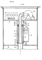
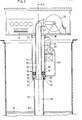
- the connecting unit generally referred to by numeral 10 substantially comprises three coaxial pipes.
- the bore of pipe 12 is connected to the fuel tank, not shown in the figure, and comprises a ring-shaped air lock 16 at the upper end thereof.
- Air lock 16 has an outer diameter slightly shorter than the inner diameter of pipe 11, while the diameter of the inner bore thereof is slightly longer than the outer diameter of inner pipe 13.
- bottom 21 of outer pipe 11 forming the cylinder has an axial circular opening having a diameter slightly longer than the outer diameter of central piston pipe 12.
- a pair of sealing members referred to by numerals 19 and 20 respectively are placed on both the outer cylindrical wall of air lock 16 and the inner cylindrical wall of the axial bore thereof. Sealing members 19 and 20 sealingly engage with the inner wall of cylinder 11 and the outer wall of inner pipe 13.
- a pair of sealing members referred to by numeral 22 are placed on the inwardly facing annular edge of the circular opening formed in the bottom of cylinder 21.
- unit- 10 thus comprises an upper annular chamber referred to by numeral 23 and a lower annular chamber referred to by numeral 24.
- Air lock 16 separates chambers 23 and 24 from each other, which chambers have varying volumes according to the position of air lock 16 within cylinder 11 since, as described above, air lock 16 and the two integral pipes of platform 14 can slide with respect to each other, as it will be more fully described.
- inner bore 25 of inner pipe 13 is .in connection with inner bore 26 of pipe 12 forming the hollow piston and accordingly, it is also in connection with the fuel feeding tank.
- the wall of cylinder 11 comprises two fittings 29 and 30 which communicate with annular chambers 23 and 24, respectively.
- fittings 29 and 30 are connected to a tank of a suitable incompressible liquid, not shown in the figure, and two delivery pipes referred to by numerals 31 and 32, respectively, through an hydraulic pump 33, it will be possible to apply a pressure either to upper annular chamber 23, thus causing the platform to be lifted, or to lower annular chamber 24, thus causing the platform to be lowered.
- hydraulic pump 33 can be supported by a bracket integrally formed with outer cylinder 11.
- This structure has a further advantage in that it allows platform 14 to rotate about axis AX of the unit at any position thereof.
Landscapes
- Engineering & Computer Science (AREA)
- Mechanical Engineering (AREA)
- Aviation & Aerospace Engineering (AREA)
- Loading And Unloading Of Fuel Tanks Or Ships (AREA)
- Actuator (AREA)
- Joints Allowing Movement (AREA)
- Other Liquid Machine Or Engine Such As Wave Power Use (AREA)
Applications Claiming Priority (2)
| Application Number | Priority Date | Filing Date | Title |
|---|---|---|---|
| IT4951983 | 1983-12-15 | ||
| IT8349519A IT1212906B (it) | 1983-12-15 | 1983-12-15 | Complesso estensibile a cilindro e pistone atto a supportare una piattaforma, mobile verticalmente, portante un apparecchio di distribuzione e a convogliare a esso un liquido sotto pressione da un sottostante serbatoio fisso |
Publications (3)
| Publication Number | Publication Date |
|---|---|
| EP0150686A2 true EP0150686A2 (de) | 1985-08-07 |
| EP0150686A3 EP0150686A3 (en) | 1985-09-25 |
| EP0150686B1 EP0150686B1 (de) | 1989-08-16 |
Family
ID=11270902
Family Applications (1)
| Application Number | Title | Priority Date | Filing Date |
|---|---|---|---|
| EP84830290A Expired EP0150686B1 (de) | 1983-12-15 | 1984-10-26 | Ausfahrbahre Zylinder- und Kolbeneinheit zur Stützung einer senkrechten beweglichen Plattform, die eine Vorrichtung zum Zuleiten von Flüssigkeit unter Druck aus einem darunterliegenden stationären Tank und eine Zapfvorrichtung hierfür aufweist |
Country Status (6)
| Country | Link |
|---|---|
| EP (1) | EP0150686B1 (de) |
| JP (1) | JPS60183393A (de) |
| CA (1) | CA1301715C (de) |
| DE (1) | DE3479416D1 (de) |
| ES (1) | ES537362A0 (de) |
| IT (1) | IT1212906B (de) |
Cited By (16)
| Publication number | Priority date | Publication date | Assignee | Title |
|---|---|---|---|---|
| DE3743393A1 (de) * | 1987-09-05 | 1989-03-23 | Fladung Gmbh Manfred | Vorrichtung zur energieversorgung von luftfahrzeugen |
| WO1991000214A1 (en) * | 1989-07-04 | 1991-01-10 | Gaetano Cutore | Shielded assembly for the delivery of fuel entirely disappearing into the ground and directly connected to the fuel tank through a manhole |
| WO1994000348A1 (en) * | 1992-06-23 | 1994-01-06 | Gaetano Cutore | Underground construction for aircraft fuel storage tanks |
| US6334457B1 (en) | 1999-03-02 | 2002-01-01 | Dresser, Inc. | Collapsing hose management system and method for gasoline dispensing unit |
| GB2428651A (en) * | 2005-08-05 | 2007-02-07 | Boeing Co | Aircraft servicing system |
| US7275715B2 (en) | 2004-05-17 | 2007-10-02 | The Boeing Company | Operational ground support system |
| US7445178B2 (en) | 2004-09-28 | 2008-11-04 | The Boeing Company | Powered nose aircraft wheel system |
| US7546978B2 (en) | 2004-05-17 | 2009-06-16 | The Boeing Company | Isolated crew deck for an operational ground support system |
| US7549607B2 (en) | 2004-05-17 | 2009-06-23 | The Boeing Company | Aircraft having a dual floor servicing system associated with an operational ground support system |
| US7575197B2 (en) | 2004-05-17 | 2009-08-18 | The Boeing Company | Mobile transporter servicing unit for an operational ground support system |
| US7578469B2 (en) | 2004-05-17 | 2009-08-25 | The Boeing Company | Terminal docking port for an operational ground support system |
| US7614585B2 (en) | 2004-05-17 | 2009-11-10 | The Boeing Company | Multi-servicing and retractable bridge for an operational ground support system |
| US8246082B2 (en) | 2008-08-20 | 2012-08-21 | Donald George Steward | Adjustable sprinkler head riser with cushioning region |
| US8430339B2 (en) | 2006-04-05 | 2013-04-30 | Donald George Stewart | Adjustable sprinkler head riser |
| DE102013011305A1 (de) * | 2013-07-02 | 2015-01-08 | Dürr Somac GmbH | Befülladapter |
| CN110985788A (zh) * | 2019-12-27 | 2020-04-10 | 浙江省机电设计研究院有限公司 | 一种液压驱动伸缩式水管及其工作方法 |
Families Citing this family (1)
| Publication number | Priority date | Publication date | Assignee | Title |
|---|---|---|---|---|
| JP2503234Y2 (ja) * | 1990-12-20 | 1996-06-26 | 株式会社大原鉄工所 | テレスコ―プ機構を有する給油ピット |
Family Cites Families (5)
| Publication number | Priority date | Publication date | Assignee | Title |
|---|---|---|---|---|
| US2061975A (en) * | 1934-11-13 | 1936-11-24 | Thomas A Martin | Automobile service lift |
| US2434824A (en) * | 1946-06-20 | 1948-01-20 | Jr Albert E Watts | Gasoline dispensing system |
| US2642957A (en) * | 1948-08-27 | 1953-06-23 | Wattpar Corp | Gasoline dispensing system for airplanes |
| FR1165661A (fr) * | 1957-01-22 | 1958-10-28 | Transport Petrol Par Pipeline | Unité de distribution de carburant pour véhicules, plus spécialement pour aérodynes |
| FR1172082A (fr) * | 1957-01-23 | 1959-02-05 | Transport Petrol Par Pipeline | Dispositif de commande d'unités de distribution de liquides, plus spécialement d'hydrocarbures |
-
1983
- 1983-12-15 IT IT8349519A patent/IT1212906B/it active
-
1984
- 1984-10-26 EP EP84830290A patent/EP0150686B1/de not_active Expired
- 1984-10-26 DE DE8484830290T patent/DE3479416D1/de not_active Expired
- 1984-11-05 ES ES537362A patent/ES537362A0/es active Granted
- 1984-11-08 CA CA000467355A patent/CA1301715C/en not_active Expired - Lifetime
- 1984-12-15 JP JP59265168A patent/JPS60183393A/ja active Granted
Cited By (20)
| Publication number | Priority date | Publication date | Assignee | Title |
|---|---|---|---|---|
| DE3743393A1 (de) * | 1987-09-05 | 1989-03-23 | Fladung Gmbh Manfred | Vorrichtung zur energieversorgung von luftfahrzeugen |
| WO1991000214A1 (en) * | 1989-07-04 | 1991-01-10 | Gaetano Cutore | Shielded assembly for the delivery of fuel entirely disappearing into the ground and directly connected to the fuel tank through a manhole |
| US5195554A (en) * | 1989-07-04 | 1993-03-23 | Cutore Gaetano | Shielded assembly for the delivery of fuel entirely disappearing into the ground and directly connected to the fuel tank through a manhole |
| JPH05503273A (ja) * | 1989-07-04 | 1993-06-03 | クトレ,ガエタノ | 地中に完全に隠蔽され、マンホールを介して燃料タンクに直接接続されている燃料を送るための遮蔽された組立体 |
| AU644596B2 (en) * | 1989-07-04 | 1993-12-16 | Gaetano Cutore | Shielded assembly for the delivery of fuel entirely disappearing into the ground and directly connected to the fuel tank through a manhole |
| WO1994000348A1 (en) * | 1992-06-23 | 1994-01-06 | Gaetano Cutore | Underground construction for aircraft fuel storage tanks |
| US6334457B1 (en) | 1999-03-02 | 2002-01-01 | Dresser, Inc. | Collapsing hose management system and method for gasoline dispensing unit |
| US7614585B2 (en) | 2004-05-17 | 2009-11-10 | The Boeing Company | Multi-servicing and retractable bridge for an operational ground support system |
| US7275715B2 (en) | 2004-05-17 | 2007-10-02 | The Boeing Company | Operational ground support system |
| US7546978B2 (en) | 2004-05-17 | 2009-06-16 | The Boeing Company | Isolated crew deck for an operational ground support system |
| US7549607B2 (en) | 2004-05-17 | 2009-06-23 | The Boeing Company | Aircraft having a dual floor servicing system associated with an operational ground support system |
| US7575197B2 (en) | 2004-05-17 | 2009-08-18 | The Boeing Company | Mobile transporter servicing unit for an operational ground support system |
| US7578469B2 (en) | 2004-05-17 | 2009-08-25 | The Boeing Company | Terminal docking port for an operational ground support system |
| US7445178B2 (en) | 2004-09-28 | 2008-11-04 | The Boeing Company | Powered nose aircraft wheel system |
| GB2428651B (en) * | 2005-08-05 | 2008-03-19 | Boeing Co | Operational ground support system for primary servicing of an aircraft |
| GB2428651A (en) * | 2005-08-05 | 2007-02-07 | Boeing Co | Aircraft servicing system |
| US8430339B2 (en) | 2006-04-05 | 2013-04-30 | Donald George Stewart | Adjustable sprinkler head riser |
| US8246082B2 (en) | 2008-08-20 | 2012-08-21 | Donald George Steward | Adjustable sprinkler head riser with cushioning region |
| DE102013011305A1 (de) * | 2013-07-02 | 2015-01-08 | Dürr Somac GmbH | Befülladapter |
| CN110985788A (zh) * | 2019-12-27 | 2020-04-10 | 浙江省机电设计研究院有限公司 | 一种液压驱动伸缩式水管及其工作方法 |
Also Published As
| Publication number | Publication date |
|---|---|
| EP0150686A3 (en) | 1985-09-25 |
| IT8349519A0 (it) | 1983-12-15 |
| CA1301715C (en) | 1992-05-26 |
| JPS60183393A (ja) | 1985-09-18 |
| IT1212906B (it) | 1989-11-30 |
| ES8507061A1 (es) | 1985-09-01 |
| DE3479416D1 (en) | 1989-09-21 |
| ES537362A0 (es) | 1985-09-01 |
| JPH0585440B2 (de) | 1993-12-07 |
| EP0150686B1 (de) | 1989-08-16 |
Similar Documents
| Publication | Publication Date | Title |
|---|---|---|
| EP0150686B1 (de) | Ausfahrbahre Zylinder- und Kolbeneinheit zur Stützung einer senkrechten beweglichen Plattform, die eine Vorrichtung zum Zuleiten von Flüssigkeit unter Druck aus einem darunterliegenden stationären Tank und eine Zapfvorrichtung hierfür aufweist | |
| US5265652A (en) | Multiaxial fuel transfer pipe system | |
| US3986732A (en) | Dual concentric vapor recovery fuel hose and end fitting therefor | |
| US6082392A (en) | Dual hose assembly and control system for truck-to-truck fuel transfer | |
| US4776615A (en) | Vapor recovery apparatus with swiveled nozzle | |
| US4260183A (en) | Pump hose swivel connection | |
| US4470437A (en) | Emergency drain device | |
| US3990731A (en) | Dual-path, multi-axis swivel coupling for discharge nozzles | |
| US2598875A (en) | Hydraulic assembly for adjustable ladder leg extension | |
| US4465266A (en) | Power unit for medical and like stools and chairs | |
| US6247492B1 (en) | Overfill protection for fuel tanks | |
| US4266582A (en) | Tank filling limiter | |
| JPS57157078A (en) | Plunger pump | |
| US4940087A (en) | Seating arrangement and structure of a spool within a well casing | |
| US3945394A (en) | Pressure-responsive valve | |
| US3961815A (en) | Leak-tight ball-and-socket connecting device transmitting torques and stresses between two pipes | |
| CA2063735A1 (en) | Shielded assembly for the delivery of fuel entirely disappearing into the ground and directly connected to the fuel tank through a manhole | |
| FR2233276B1 (de) | ||
| US3388719A (en) | Internal tank valves | |
| WO1989008189A1 (en) | Bore hole pump | |
| US4258744A (en) | Vertically movable apparatus for fluid delivery from stationary source | |
| US5511582A (en) | Compensating valve for control of fluid flow | |
| IT1146571B (it) | Dispositivo di fermo adatto per fissare la pasizione,rispetto al pavimento,di sedie con rotelle | |
| US4444251A (en) | Combined installation comprising an activation pump and a safety valve disposed below this pump, in a hydrocarbon production well | |
| US4646794A (en) | Telescopic rotary refueling system for battle tank |
Legal Events
| Date | Code | Title | Description |
|---|---|---|---|
| PUAI | Public reference made under article 153(3) epc to a published international application that has entered the european phase |
Free format text: ORIGINAL CODE: 0009012 |
|
| PUAL | Search report despatched |
Free format text: ORIGINAL CODE: 0009013 |
|
| AK | Designated contracting states |
Designated state(s): DE FR GB |
|
| AK | Designated contracting states |
Designated state(s): DE FR GB |
|
| 17P | Request for examination filed |
Effective date: 19860324 |
|
| 17Q | First examination report despatched |
Effective date: 19861208 |
|
| GRAA | (expected) grant |
Free format text: ORIGINAL CODE: 0009210 |
|
| AK | Designated contracting states |
Kind code of ref document: B1 Designated state(s): DE FR GB |
|
| REF | Corresponds to: |
Ref document number: 3479416 Country of ref document: DE Date of ref document: 19890921 |
|
| ET | Fr: translation filed | ||
| PLBE | No opposition filed within time limit |
Free format text: ORIGINAL CODE: 0009261 |
|
| STAA | Information on the status of an ep patent application or granted ep patent |
Free format text: STATUS: NO OPPOSITION FILED WITHIN TIME LIMIT |
|
| 26N | No opposition filed | ||
| PGFP | Annual fee paid to national office [announced via postgrant information from national office to epo] |
Ref country code: GB Payment date: 20001017 Year of fee payment: 17 |
|
| PGFP | Annual fee paid to national office [announced via postgrant information from national office to epo] |
Ref country code: FR Payment date: 20001031 Year of fee payment: 17 |
|
| PGFP | Annual fee paid to national office [announced via postgrant information from national office to epo] |
Ref country code: DE Payment date: 20001219 Year of fee payment: 17 |
|
| PG25 | Lapsed in a contracting state [announced via postgrant information from national office to epo] |
Ref country code: GB Free format text: LAPSE BECAUSE OF NON-PAYMENT OF DUE FEES Effective date: 20011026 |
|
| REG | Reference to a national code |
Ref country code: GB Ref legal event code: IF02 |
|
| GBPC | Gb: european patent ceased through non-payment of renewal fee |
Effective date: 20011026 |
|
| PG25 | Lapsed in a contracting state [announced via postgrant information from national office to epo] |
Ref country code: FR Free format text: LAPSE BECAUSE OF NON-PAYMENT OF DUE FEES Effective date: 20020628 |
|
| PG25 | Lapsed in a contracting state [announced via postgrant information from national office to epo] |
Ref country code: DE Free format text: LAPSE BECAUSE OF NON-PAYMENT OF DUE FEES Effective date: 20020702 |
|
| REG | Reference to a national code |
Ref country code: FR Ref legal event code: ST |