EP0150738B1 - Misch- und Abgabegerät für Flüssigkeiten - Google Patents
Misch- und Abgabegerät für Flüssigkeiten Download PDFInfo
- Publication number
- EP0150738B1 EP0150738B1 EP85100245A EP85100245A EP0150738B1 EP 0150738 B1 EP0150738 B1 EP 0150738B1 EP 85100245 A EP85100245 A EP 85100245A EP 85100245 A EP85100245 A EP 85100245A EP 0150738 B1 EP0150738 B1 EP 0150738B1
- Authority
- EP
- European Patent Office
- Prior art keywords
- nozzle
- liquid mixing
- mixing
- agitating
- bar
- Prior art date
- Legal status (The legal status is an assumption and is not a legal conclusion. Google has not performed a legal analysis and makes no representation as to the accuracy of the status listed.)
- Expired
Links
- 239000007788 liquid Substances 0.000 title claims description 20
- 238000013019 agitation Methods 0.000 claims description 2
- 239000003795 chemical substances by application Substances 0.000 description 8
- 230000007246 mechanism Effects 0.000 description 8
- 239000000853 adhesive Substances 0.000 description 6
- 230000001070 adhesive effect Effects 0.000 description 6
- 239000000203 mixture Substances 0.000 description 3
- XEEYBQQBJWHFJM-UHFFFAOYSA-N Iron Chemical compound [Fe] XEEYBQQBJWHFJM-UHFFFAOYSA-N 0.000 description 2
- 238000010438 heat treatment Methods 0.000 description 2
- 239000000463 material Substances 0.000 description 2
- 210000003813 thumb Anatomy 0.000 description 2
- 239000000919 ceramic Substances 0.000 description 1
- 238000006243 chemical reaction Methods 0.000 description 1
- 239000011248 coating agent Substances 0.000 description 1
- 238000000576 coating method Methods 0.000 description 1
- 230000000694 effects Effects 0.000 description 1
- 229910052742 iron Inorganic materials 0.000 description 1
- 238000003475 lamination Methods 0.000 description 1
- 229910001120 nichrome Inorganic materials 0.000 description 1
- 238000007711 solidification Methods 0.000 description 1
- 230000008023 solidification Effects 0.000 description 1
Images


Classifications
-
- B—PERFORMING OPERATIONS; TRANSPORTING
- B05—SPRAYING OR ATOMISING IN GENERAL; APPLYING FLUENT MATERIALS TO SURFACES, IN GENERAL
- B05C—APPARATUS FOR APPLYING FLUENT MATERIALS TO SURFACES, IN GENERAL
- B05C17/00—Hand tools or apparatus using hand held tools, for applying liquids or other fluent materials to, for spreading applied liquids or other fluent materials on, or for partially removing applied liquids or other fluent materials from, surfaces
- B05C17/005—Hand tools or apparatus using hand held tools, for applying liquids or other fluent materials to, for spreading applied liquids or other fluent materials on, or for partially removing applied liquids or other fluent materials from, surfaces for discharging material from a reservoir or container located in or on the hand tool through an outlet orifice by pressure without using surface contacting members like pads or brushes
- B05C17/00503—Details of the outlet element
- B05C17/00516—Shape or geometry of the outlet orifice or the outlet element
-
- B—PERFORMING OPERATIONS; TRANSPORTING
- B01—PHYSICAL OR CHEMICAL PROCESSES OR APPARATUS IN GENERAL
- B01F—MIXING, e.g. DISSOLVING, EMULSIFYING OR DISPERSING
- B01F35/00—Accessories for mixers; Auxiliary operations or auxiliary devices; Parts or details of general application
- B01F35/30—Driving arrangements; Transmissions; Couplings; Brakes
- B01F35/32—Driving arrangements
-
- B—PERFORMING OPERATIONS; TRANSPORTING
- B01—PHYSICAL OR CHEMICAL PROCESSES OR APPARATUS IN GENERAL
- B01F—MIXING, e.g. DISSOLVING, EMULSIFYING OR DISPERSING
- B01F25/00—Flow mixers; Mixers for falling materials, e.g. solid particles
- B01F25/40—Static mixers
- B01F25/42—Static mixers in which the mixing is affected by moving the components jointly in changing directions, e.g. in tubes provided with baffles or obstructions
- B01F25/43—Mixing tubes, e.g. wherein the material is moved in a radial or partly reversed direction
- B01F25/432—Mixing tubes, e.g. wherein the material is moved in a radial or partly reversed direction with means for dividing the material flow into separate sub-flows and for repositioning and recombining these sub-flows; Cross-mixing, e.g. conducting the outer layer of the material nearer to the axis of the tube or vice-versa
- B01F25/4321—Mixing tubes, e.g. wherein the material is moved in a radial or partly reversed direction with means for dividing the material flow into separate sub-flows and for repositioning and recombining these sub-flows; Cross-mixing, e.g. conducting the outer layer of the material nearer to the axis of the tube or vice-versa the subflows consisting of at least two flat layers which are recombined, e.g. using means having restriction or expansion zones
-
- B—PERFORMING OPERATIONS; TRANSPORTING
- B01—PHYSICAL OR CHEMICAL PROCESSES OR APPARATUS IN GENERAL
- B01F—MIXING, e.g. DISSOLVING, EMULSIFYING OR DISPERSING
- B01F31/00—Mixers with shaking, oscillating, or vibrating mechanisms
- B01F31/40—Mixers with shaking, oscillating, or vibrating mechanisms with an axially oscillating rotary stirrer
-
- B—PERFORMING OPERATIONS; TRANSPORTING
- B01—PHYSICAL OR CHEMICAL PROCESSES OR APPARATUS IN GENERAL
- B01F—MIXING, e.g. DISSOLVING, EMULSIFYING OR DISPERSING
- B01F33/00—Other mixers; Mixing plants; Combinations of mixers
- B01F33/50—Movable or transportable mixing devices or plants
- B01F33/501—Movable mixing devices, i.e. readily shifted or displaced from one place to another, e.g. portable during use
- B01F33/5011—Movable mixing devices, i.e. readily shifted or displaced from one place to another, e.g. portable during use portable during use, e.g. hand-held
-
- B—PERFORMING OPERATIONS; TRANSPORTING
- B01—PHYSICAL OR CHEMICAL PROCESSES OR APPARATUS IN GENERAL
- B01F—MIXING, e.g. DISSOLVING, EMULSIFYING OR DISPERSING
- B01F35/00—Accessories for mixers; Auxiliary operations or auxiliary devices; Parts or details of general application
- B01F35/30—Driving arrangements; Transmissions; Couplings; Brakes
-
- B—PERFORMING OPERATIONS; TRANSPORTING
- B01—PHYSICAL OR CHEMICAL PROCESSES OR APPARATUS IN GENERAL
- B01F—MIXING, e.g. DISSOLVING, EMULSIFYING OR DISPERSING
- B01F35/00—Accessories for mixers; Auxiliary operations or auxiliary devices; Parts or details of general application
- B01F35/30—Driving arrangements; Transmissions; Couplings; Brakes
- B01F35/32—Driving arrangements
- B01F35/32005—Type of drive
- B01F35/32025—Battery driven
-
- B—PERFORMING OPERATIONS; TRANSPORTING
- B01—PHYSICAL OR CHEMICAL PROCESSES OR APPARATUS IN GENERAL
- B01F—MIXING, e.g. DISSOLVING, EMULSIFYING OR DISPERSING
- B01F35/00—Accessories for mixers; Auxiliary operations or auxiliary devices; Parts or details of general application
- B01F35/30—Driving arrangements; Transmissions; Couplings; Brakes
- B01F35/32—Driving arrangements
- B01F35/32005—Type of drive
- B01F35/3204—Motor driven, i.e. by means of an electric or IC motor
-
- B—PERFORMING OPERATIONS; TRANSPORTING
- B01—PHYSICAL OR CHEMICAL PROCESSES OR APPARATUS IN GENERAL
- B01F—MIXING, e.g. DISSOLVING, EMULSIFYING OR DISPERSING
- B01F35/00—Accessories for mixers; Auxiliary operations or auxiliary devices; Parts or details of general application
- B01F35/71—Feed mechanisms
- B01F35/716—Feed mechanisms characterised by the relative arrangement of the containers for feeding or mixing the components
- B01F35/7164—Feed mechanisms characterised by the relative arrangement of the containers for feeding or mixing the components the containers being placed in parallel before contacting the contents
-
- B—PERFORMING OPERATIONS; TRANSPORTING
- B05—SPRAYING OR ATOMISING IN GENERAL; APPLYING FLUENT MATERIALS TO SURFACES, IN GENERAL
- B05C—APPARATUS FOR APPLYING FLUENT MATERIALS TO SURFACES, IN GENERAL
- B05C17/00—Hand tools or apparatus using hand held tools, for applying liquids or other fluent materials to, for spreading applied liquids or other fluent materials on, or for partially removing applied liquids or other fluent materials from, surfaces
- B05C17/005—Hand tools or apparatus using hand held tools, for applying liquids or other fluent materials to, for spreading applied liquids or other fluent materials on, or for partially removing applied liquids or other fluent materials from, surfaces for discharging material from a reservoir or container located in or on the hand tool through an outlet orifice by pressure without using surface contacting members like pads or brushes
- B05C17/00553—Hand tools or apparatus using hand held tools, for applying liquids or other fluent materials to, for spreading applied liquids or other fluent materials on, or for partially removing applied liquids or other fluent materials from, surfaces for discharging material from a reservoir or container located in or on the hand tool through an outlet orifice by pressure without using surface contacting members like pads or brushes with means allowing the stock of material to consist of at least two different components
-
- B—PERFORMING OPERATIONS; TRANSPORTING
- B05—SPRAYING OR ATOMISING IN GENERAL; APPLYING FLUENT MATERIALS TO SURFACES, IN GENERAL
- B05C—APPARATUS FOR APPLYING FLUENT MATERIALS TO SURFACES, IN GENERAL
- B05C17/00—Hand tools or apparatus using hand held tools, for applying liquids or other fluent materials to, for spreading applied liquids or other fluent materials on, or for partially removing applied liquids or other fluent materials from, surfaces
- B05C17/005—Hand tools or apparatus using hand held tools, for applying liquids or other fluent materials to, for spreading applied liquids or other fluent materials on, or for partially removing applied liquids or other fluent materials from, surfaces for discharging material from a reservoir or container located in or on the hand tool through an outlet orifice by pressure without using surface contacting members like pads or brushes
- B05C17/00553—Hand tools or apparatus using hand held tools, for applying liquids or other fluent materials to, for spreading applied liquids or other fluent materials on, or for partially removing applied liquids or other fluent materials from, surfaces for discharging material from a reservoir or container located in or on the hand tool through an outlet orifice by pressure without using surface contacting members like pads or brushes with means allowing the stock of material to consist of at least two different components
- B05C17/00566—Hand tools or apparatus using hand held tools, for applying liquids or other fluent materials to, for spreading applied liquids or other fluent materials on, or for partially removing applied liquids or other fluent materials from, surfaces for discharging material from a reservoir or container located in or on the hand tool through an outlet orifice by pressure without using surface contacting members like pads or brushes with means allowing the stock of material to consist of at least two different components with a dynamic mixer in the nozzle
-
- B—PERFORMING OPERATIONS; TRANSPORTING
- B01—PHYSICAL OR CHEMICAL PROCESSES OR APPARATUS IN GENERAL
- B01F—MIXING, e.g. DISSOLVING, EMULSIFYING OR DISPERSING
- B01F2101/00—Mixing characterised by the nature of the mixed materials or by the application field
- B01F2101/2305—Mixers of the two-component package type, i.e. where at least two components are separately stored, and are mixed in the moment of application
-
- B—PERFORMING OPERATIONS; TRANSPORTING
- B01—PHYSICAL OR CHEMICAL PROCESSES OR APPARATUS IN GENERAL
- B01F—MIXING, e.g. DISSOLVING, EMULSIFYING OR DISPERSING
- B01F2215/00—Auxiliary or complementary information in relation with mixing
- B01F2215/04—Technical information in relation with mixing
- B01F2215/0404—Technical information in relation with mixing theories or general explanations of phenomena associated with mixing or generalizations of a concept by comparison of equivalent methods
-
- B—PERFORMING OPERATIONS; TRANSPORTING
- B01—PHYSICAL OR CHEMICAL PROCESSES OR APPARATUS IN GENERAL
- B01F—MIXING, e.g. DISSOLVING, EMULSIFYING OR DISPERSING
- B01F27/00—Mixers with rotary stirring devices in fixed receptacles; Kneaders
- B01F27/05—Stirrers
- B01F27/11—Stirrers characterised by the configuration of the stirrers
- B01F27/112—Stirrers characterised by the configuration of the stirrers with arms, paddles, vanes or blades
- B01F27/1121—Stirrers characterised by the configuration of the stirrers with arms, paddles, vanes or blades pin-shaped
-
- B—PERFORMING OPERATIONS; TRANSPORTING
- B01—PHYSICAL OR CHEMICAL PROCESSES OR APPARATUS IN GENERAL
- B01F—MIXING, e.g. DISSOLVING, EMULSIFYING OR DISPERSING
- B01F27/00—Mixers with rotary stirring devices in fixed receptacles; Kneaders
- B01F27/05—Stirrers
- B01F27/11—Stirrers characterised by the configuration of the stirrers
- B01F27/112—Stirrers characterised by the configuration of the stirrers with arms, paddles, vanes or blades
- B01F27/1125—Stirrers characterised by the configuration of the stirrers with arms, paddles, vanes or blades with vanes or blades extending parallel or oblique to the stirrer axis
-
- B—PERFORMING OPERATIONS; TRANSPORTING
- B01—PHYSICAL OR CHEMICAL PROCESSES OR APPARATUS IN GENERAL
- B01F—MIXING, e.g. DISSOLVING, EMULSIFYING OR DISPERSING
- B01F27/00—Mixers with rotary stirring devices in fixed receptacles; Kneaders
- B01F27/05—Stirrers
- B01F27/11—Stirrers characterised by the configuration of the stirrers
- B01F27/113—Propeller-shaped stirrers for producing an axial flow, e.g. shaped like a ship or aircraft propeller
-
- B—PERFORMING OPERATIONS; TRANSPORTING
- B01—PHYSICAL OR CHEMICAL PROCESSES OR APPARATUS IN GENERAL
- B01F—MIXING, e.g. DISSOLVING, EMULSIFYING OR DISPERSING
- B01F27/00—Mixers with rotary stirring devices in fixed receptacles; Kneaders
- B01F27/05—Stirrers
- B01F27/11—Stirrers characterised by the configuration of the stirrers
- B01F27/114—Helically shaped stirrers, i.e. stirrers comprising a helically shaped band or helically shaped band sections
- B01F27/1143—Helically shaped stirrers, i.e. stirrers comprising a helically shaped band or helically shaped band sections screw-shaped, e.g. worms
-
- B—PERFORMING OPERATIONS; TRANSPORTING
- B01—PHYSICAL OR CHEMICAL PROCESSES OR APPARATUS IN GENERAL
- B01F—MIXING, e.g. DISSOLVING, EMULSIFYING OR DISPERSING
- B01F35/00—Accessories for mixers; Auxiliary operations or auxiliary devices; Parts or details of general application
- B01F35/30—Driving arrangements; Transmissions; Couplings; Brakes
- B01F35/32—Driving arrangements
- B01F35/32005—Type of drive
-
- B—PERFORMING OPERATIONS; TRANSPORTING
- B01—PHYSICAL OR CHEMICAL PROCESSES OR APPARATUS IN GENERAL
- B01F—MIXING, e.g. DISSOLVING, EMULSIFYING OR DISPERSING
- B01F35/00—Accessories for mixers; Auxiliary operations or auxiliary devices; Parts or details of general application
- B01F35/30—Driving arrangements; Transmissions; Couplings; Brakes
- B01F35/32—Driving arrangements
- B01F35/32005—Type of drive
- B01F35/3202—Hand driven
-
- B—PERFORMING OPERATIONS; TRANSPORTING
- B05—SPRAYING OR ATOMISING IN GENERAL; APPLYING FLUENT MATERIALS TO SURFACES, IN GENERAL
- B05C—APPARATUS FOR APPLYING FLUENT MATERIALS TO SURFACES, IN GENERAL
- B05C17/00—Hand tools or apparatus using hand held tools, for applying liquids or other fluent materials to, for spreading applied liquids or other fluent materials on, or for partially removing applied liquids or other fluent materials from, surfaces
- B05C17/005—Hand tools or apparatus using hand held tools, for applying liquids or other fluent materials to, for spreading applied liquids or other fluent materials on, or for partially removing applied liquids or other fluent materials from, surfaces for discharging material from a reservoir or container located in or on the hand tool through an outlet orifice by pressure without using surface contacting members like pads or brushes
- B05C17/01—Hand tools or apparatus using hand held tools, for applying liquids or other fluent materials to, for spreading applied liquids or other fluent materials on, or for partially removing applied liquids or other fluent materials from, surfaces for discharging material from a reservoir or container located in or on the hand tool through an outlet orifice by pressure without using surface contacting members like pads or brushes with manually mechanically or electrically actuated piston or the like
Definitions
- the invention relates to a liquid mixing extractor according to the preamble of claim 1.
- Such a liquid mixing extractor is known from EP-A-57 465. After use of this extractor, mixed liquid, like an adhesive material, remains in the nozzle so that this nozzle cannot be used again, since the remaining material clogs up the nozzle.
- the two sections of the mixing part can be opened so as to easily remove remaining liquid or adhesive so that the extractor with the nozzle can be used again.
- the liquid mixing extractor is equipped with a plurality of cylinders in parallel, and the front ends of these cylinders are united into one body at a mixing nozzle having an agitating function, whereby a plurality of the liquid agents are pressed out in complete mixture.
- Figs. 1 to 3 illustrate an embodiment where the liquid agents are agitated and mixed by an agitating bar to be rotated by a motor.
- the cylinders 1, 1 herein are double into which double pistons 2, 2 are inserted from the rear side of the shown mixing extractor, and are connected via a thumb plate 3.
- a mixing nozzle 4 is provided at the front end of the cylinders. As seen in Figs. 6 and 8, the nozzle 4 communicates with flow passages from the cylinders.
- the agitating bar 6 goes into the mixing nozzle 4 at its end portion. As end portions of the agitating bars, various kinds will be - assumed, and Figs. 3A to D show some examples thereof.
- Fig. 3A shows that lots of bar like projections 7 are radially extended from the agitating bar 6.
- Fig. 3B shows that plate like projections 8 are substituted for the bar like ones 7.
- Fig. 3C show that the agitating bar 6 is formed in wave.
- Fig. 3D shows that the agitating bar 6 is formed in crank shape.
- the motor 5 has a power source of a cell 9, and it is preferable that the motor 5 and the cell 9 are, as seen in Fig. 2, positioned above the cylinders 1, 1.
- Figs. 4 and 5 illustrate mechanisms of reciprocating the agitating bar 6.
- Fig. 4 shows a cam 10 to be rotated by a motor 11.
- the cam 10 such as a cylindrical cam is preferable.
- the agitating bar 6 is secured by mounting on a coil spring 12 between the cylinders 1, 1. Therefore, the agitating bar 6 is pushed in accompany of rotation of the cam 10 and returned by the coil spring 12, so that it is reciprocated laterally.
- Fig. 5 shows that a magnet 13 or an iron piece is secured on the agitating bar 6 and held between a couple of magnets, 14, 15, and either plus or minus of the magnets 14, 15 is successively broken, so that the agitating bar 6 is moved.
- the end points of the agitating bar 6 of Figs. 4 and 5 are shaped in the same as said above.
- Fig. 6 shows an embodiment having a screw 17 to be rotated by the motor 16 at a junction of the mixing nozzle 4.
- Fig. 7 shows an embodiment covered with a heater 18 around an outer circumference of the mixing nozzle 4.
- This heater 18 heats the liquids flowing within the mixing nozzle 4.
- the mixing nozzle 4 is preferably made of such as cupper or the like of high heat conductivity.
- the heater 18 may be made of a resistor as nichrome wire. If a ceramic heater is used, a desired temperature may be easily obtained without a control circuit.
- the viscosity is lowered so that the fluidity is inceased and workability is heightened such as mixture, defoam and coating.
- time for solidification is saved.
- Fig. 8 shows an embodiment positioning a spiral heater 19 of a cartridge type in a junction of the mixing nozzle 4.
- the adhesive within the mixing nozzle 4 is heated by the heater 19 and follows the spiral.
- the heating effect is as said above.
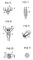
- Fig. 9 shows an embodiment comprising a zigzag plate 20 to be positioned at a junction of the mixing nozzle 4.
- Fig. 10 illustrates mixing thereby.
- the liquid agents are supplied at both sides A and B of the zigzag plate 20, the liquid agents are partitioned by the zigzag 20 as seen in Fig. 11 and taken out in lamination.
- Fig. 12 shows an embodiment rotating the agitating bar 6 by pushing a piston 2.
- the cylinder 1 is provided with a flange 22 defined with a female screw 21 into which a screw shaft 23 is screwed, the screw shaft 23 being held with a thumb plate 3 at its rear side and provided with a driving gear 24 at its front end to be geared with a gear 25 fixed to the agitating bar 6 pivoted on the cylinder 1.
- the end point of the agitating bar 6 is as mentioned above and positioned within the mixing nozzle 4.
- Fig. 13 shows an embodiment having a handle 26 on the cylinder 1.
- the handle 26 and the agitating bar 6 are connected via bevel gears 27, 28. If the handle 26 is rotated, the agitating bar 6 is driven.
- Fig. 14 shows the mixing part of the nozzle 4 which is divided into two longitudinal sections, and each of them is provided with weirs 29 in obliquity.
- the adhesives change the flowing direction by means of the weirs 29, and are agitated and mixed.
- the remaining adhesive solidified after use is easily removed by opening the mixing part.
- the adhesive is charged into the cartridge and set in the cylinder 1, or it is directly poured into the cylinder.
- the agitating and mixing mechanism is furnished in the mixing nozzle, and a plurality of the liquid agents may be exactly agitated and mixed.
- Preferred embodiments are a device, wherein the agitating bar is moved reciprocately by means of plus or minus function of a magnet.
Landscapes
- Chemical & Material Sciences (AREA)
- Chemical Kinetics & Catalysis (AREA)
- Engineering & Computer Science (AREA)
- Mechanical Engineering (AREA)
- Dispersion Chemistry (AREA)
- Physics & Mathematics (AREA)
- Geometry (AREA)
- Coating Apparatus (AREA)
- Mixers Of The Rotary Stirring Type (AREA)
- Dental Tools And Instruments Or Auxiliary Dental Instruments (AREA)
- Accessories For Mixers (AREA)
Claims (6)
Applications Claiming Priority (2)
| Application Number | Priority Date | Filing Date | Title |
|---|---|---|---|
| JP4442/84 | 1984-01-13 | ||
| JP59004442A JPS60150820A (ja) | 1984-01-13 | 1984-01-13 | 撹拌混合注液具 |
Publications (3)
| Publication Number | Publication Date |
|---|---|
| EP0150738A2 EP0150738A2 (de) | 1985-08-07 |
| EP0150738A3 EP0150738A3 (en) | 1986-01-15 |
| EP0150738B1 true EP0150738B1 (de) | 1988-10-12 |
Family
ID=11584317
Family Applications (1)
| Application Number | Title | Priority Date | Filing Date |
|---|---|---|---|
| EP85100245A Expired EP0150738B1 (de) | 1984-01-13 | 1985-01-11 | Misch- und Abgabegerät für Flüssigkeiten |
Country Status (3)
| Country | Link |
|---|---|
| EP (1) | EP0150738B1 (de) |
| JP (1) | JPS60150820A (de) |
| DE (1) | DE3565478D1 (de) |
Cited By (1)
| Publication number | Priority date | Publication date | Assignee | Title |
|---|---|---|---|---|
| DE3920694A1 (de) * | 1989-06-24 | 1991-01-10 | Friedhelm Schneider | Dosierpistole fuer zwei komponenten mit dynamischer mischkammer |
Families Citing this family (10)
| Publication number | Priority date | Publication date | Assignee | Title |
|---|---|---|---|---|
| GB2249171A (en) * | 1990-10-25 | 1992-04-29 | N Proizv Ob Biolog Priborostro | Liquid sampling |
| DE9017323U1 (de) * | 1990-12-21 | 1992-04-16 | Thera Patent GmbH & Co KG Gesellschaft für industrielle Schutzrechte, 8031 Seefeld | Dynamischer Mischer |
| DE9017322U1 (de) * | 1990-12-21 | 1992-04-16 | THERA Patent GmbH & Co. KG Gesellschaft für industrielle Schutzrechte, 82229 Seefeld | Gerät zum Mischen und Ausbringen von Mehrkomponenten-Massen |
| DE4235736C1 (de) * | 1992-10-23 | 1994-03-24 | Bergmann Franz Josef | Vorrichtung zum Mischen und Austragen pastöser Massen |
| EP0723807B1 (de) * | 1995-01-16 | 2001-09-19 | Wilhelm A. Keller | Mischer und Mehrkomponentenabgabevorrichtung sowie Verfahren zur ausgerichteten Verbindung des Mischers mit der Mehrkomponentenabgabevorrichtung |
| DE10351828B4 (de) * | 2003-11-06 | 2006-03-30 | Hilti Ag | Auspressvorrichtung |
| US8197122B2 (en) * | 2008-04-24 | 2012-06-12 | Tyco Healthcare Group Lp | Dynamic mixing applicator |
| US8960501B2 (en) | 2012-10-23 | 2015-02-24 | Nordson Corporation | Dispensing assembly and method for dispensing a mixed fluid |
| CN108939980B (zh) * | 2018-08-01 | 2020-09-18 | 漯河医学高等专科学校 | 一种用于检验的过滤搅拌箱 |
| CN117358094B (zh) * | 2023-12-07 | 2024-03-05 | 江苏康泰环保股份有限公司 | 一种水处理喷淋装置 |
Family Cites Families (4)
| Publication number | Priority date | Publication date | Assignee | Title |
|---|---|---|---|---|
| DE1486405A1 (de) * | 1965-04-15 | 1969-06-04 | H V Hardman Company Inc | Vorrichtung zum Mischen und Abgeben von Materialien |
| DE2821369A1 (de) * | 1978-05-16 | 1979-11-22 | Willi Bagh | Geraet fuer zweikomponenten-dichtstoffe |
| DE3047312A1 (de) * | 1980-12-16 | 1982-07-29 | Hilti AG, 9494 Schaan | Geraet zum verfuellen von bohrloechern |
| DE3103610A1 (de) * | 1981-02-03 | 1982-08-19 | Gebrüder Kömmerling Kunststoffwerke GmbH, 6780 Pirmasens | Hand-mischspritze |
-
1984
- 1984-01-13 JP JP59004442A patent/JPS60150820A/ja active Pending
-
1985
- 1985-01-11 DE DE8585100245T patent/DE3565478D1/de not_active Expired
- 1985-01-11 EP EP85100245A patent/EP0150738B1/de not_active Expired
Cited By (1)
| Publication number | Priority date | Publication date | Assignee | Title |
|---|---|---|---|---|
| DE3920694A1 (de) * | 1989-06-24 | 1991-01-10 | Friedhelm Schneider | Dosierpistole fuer zwei komponenten mit dynamischer mischkammer |
Also Published As
| Publication number | Publication date |
|---|---|
| EP0150738A2 (de) | 1985-08-07 |
| DE3565478D1 (en) | 1988-11-17 |
| JPS60150820A (ja) | 1985-08-08 |
| EP0150738A3 (en) | 1986-01-15 |
Similar Documents
| Publication | Publication Date | Title |
|---|---|---|
| EP0150738A2 (de) | Misch- und Abgabegerät für Flüssigkeiten | |
| ATE311137T1 (de) | Küchenmaschine mit einem rührgefäss und einem antrieb für ein rührwerk in dem rührgefäss | |
| EP2227118B1 (de) | Automatischer milchschaumbereiter | |
| EP1510162A3 (de) | Mischgerät für Nahrungsmittel | |
| WO1999003384A1 (de) | Mobile vorrichtung zum rühren und erwärmen von flüssigen oder breiförmigen substanzen | |
| EP0361053A3 (de) | Heizvorrichtung für den Fahrgastraum eines eine flüssigkeitsgekühlte Brennkraftmaschine aufweisenden Kraftfahrzeuges | |
| EP1233244A3 (de) | Induktionsofen und Bodenabstichmechanismus | |
| US6216917B1 (en) | Dispensing system and method | |
| DE2337328C2 (de) | Elektrischer Regelantrieb | |
| EP0946279B1 (de) | Reaktionskammersystem für die chemische synthese oder verwandte anwendungen | |
| CA2183884A1 (en) | Metering cap with integral pump-motor hand operated mixing facility | |
| US3704076A (en) | Screw feeder for paste-like materials | |
| US9897081B2 (en) | Heating positive-displacement liquid pump | |
| GB2031292A (en) | Apparatus for homogenization and thermal treatment of liquids | |
| DE60102739T2 (de) | Dosier- und Austragsvorrichtung für ein- oder zweikomponentigen Klebstoff | |
| US4715724A (en) | Head attachment for a hydraulic synthetic-resin working machine for colored synthetic resin | |
| US2970818A (en) | Mixing apparatus | |
| RU2062667C1 (ru) | Устройство для ультразвуковой очистки деталей | |
| KR101890811B1 (ko) | 원단 도포용 액상 실리콘 배합 장치 | |
| ATE2204T1 (de) | Vorrichtung zum dosieren und mischen von fluessigen zweikomponenten-kunststoffen. | |
| CN220496254U (zh) | 一种配料罐 | |
| EP0278953B1 (de) | Universelle vorrichtung zur seifenextrudierung | |
| US3961776A (en) | Mixing and kneading device | |
| PL181699B1 (pl) | Zestaw do wytwarzania masy z konglomeratu kamienia naturalnego | |
| DE19647922C2 (de) | Verfahren und Vorrichtung zur Erwärmung von viskosen Massen, insbesondere Gießharz oder anderen Materialien mit vergleichbaren dipolaren Eigenschaften, durch Mikrowellenergie |
Legal Events
| Date | Code | Title | Description |
|---|---|---|---|
| PUAI | Public reference made under article 153(3) epc to a published international application that has entered the european phase |
Free format text: ORIGINAL CODE: 0009012 |
|
| AK | Designated contracting states |
Designated state(s): DE FR GB IT |
|
| PUAL | Search report despatched |
Free format text: ORIGINAL CODE: 0009013 |
|
| AK | Designated contracting states |
Designated state(s): DE FR GB IT |
|
| 17P | Request for examination filed |
Effective date: 19860603 |
|
| 17Q | First examination report despatched |
Effective date: 19870206 |
|
| GRAA | (expected) grant |
Free format text: ORIGINAL CODE: 0009210 |
|
| AK | Designated contracting states |
Kind code of ref document: B1 Designated state(s): DE FR GB IT |
|
| PG25 | Lapsed in a contracting state [announced via postgrant information from national office to epo] |
Ref country code: IT Free format text: LAPSE BECAUSE OF FAILURE TO SUBMIT A TRANSLATION OF THE DESCRIPTION OR TO PAY THE FEE WITHIN THE PRESCRIBED TIME-LIMIT;WARNING: LAPSES OF ITALIAN PATENTS WITH EFFECTIVE DATE BEFORE 2007 MAY HAVE OCCURRED AT ANY TIME BEFORE 2007. THE CORRECT EFFECTIVE DATE MAY BE DIFFERENT FROM THE ONE RECORDED. Effective date: 19881012 |
|
| REF | Corresponds to: |
Ref document number: 3565478 Country of ref document: DE Date of ref document: 19881117 |
|
| ET | Fr: translation filed | ||
| PLBE | No opposition filed within time limit |
Free format text: ORIGINAL CODE: 0009261 |
|
| STAA | Information on the status of an ep patent application or granted ep patent |
Free format text: STATUS: NO OPPOSITION FILED WITHIN TIME LIMIT |
|
| 26N | No opposition filed | ||
| PGFP | Annual fee paid to national office [announced via postgrant information from national office to epo] |
Ref country code: FR Payment date: 19901227 Year of fee payment: 7 |
|
| PGFP | Annual fee paid to national office [announced via postgrant information from national office to epo] |
Ref country code: GB Payment date: 19910102 Year of fee payment: 7 |
|
| PGFP | Annual fee paid to national office [announced via postgrant information from national office to epo] |
Ref country code: DE Payment date: 19910315 Year of fee payment: 7 |
|
| PG25 | Lapsed in a contracting state [announced via postgrant information from national office to epo] |
Ref country code: GB Effective date: 19920111 |
|
| GBPC | Gb: european patent ceased through non-payment of renewal fee | ||
| PG25 | Lapsed in a contracting state [announced via postgrant information from national office to epo] |
Ref country code: FR Effective date: 19920930 |
|
| PG25 | Lapsed in a contracting state [announced via postgrant information from national office to epo] |
Ref country code: DE Effective date: 19921001 |
|
| REG | Reference to a national code |
Ref country code: FR Ref legal event code: ST |