EP0150828A1 - Appareil pour reproduire un signal vidéo - Google Patents
Appareil pour reproduire un signal vidéo Download PDFInfo
- Publication number
- EP0150828A1 EP0150828A1 EP85100778A EP85100778A EP0150828A1 EP 0150828 A1 EP0150828 A1 EP 0150828A1 EP 85100778 A EP85100778 A EP 85100778A EP 85100778 A EP85100778 A EP 85100778A EP 0150828 A1 EP0150828 A1 EP 0150828A1
- Authority
- EP
- European Patent Office
- Prior art keywords
- magnetic head
- rotary magnetic
- period
- magnetic tape
- circuit
- Prior art date
- Legal status (The legal status is an assumption and is not a legal conclusion. Google has not performed a legal analysis and makes no representation as to the accuracy of the status listed.)
- Granted
Links
Images



Classifications
-
- G—PHYSICS
- G11—INFORMATION STORAGE
- G11B—INFORMATION STORAGE BASED ON RELATIVE MOVEMENT BETWEEN RECORD CARRIER AND TRANSDUCER
- G11B5/00—Recording by magnetisation or demagnetisation of a record carrier; Reproducing by magnetic means; Record carriers therefor
- G11B5/48—Disposition or mounting of heads or head supports relative to record carriers ; arrangements of heads, e.g. for scanning the record carrier to increase the relative speed
- G11B5/58—Disposition or mounting of heads or head supports relative to record carriers ; arrangements of heads, e.g. for scanning the record carrier to increase the relative speed with provision for moving the head for the purpose of maintaining alignment of the head relative to the record carrier during transducing operation, e.g. to compensate for surface irregularities of the latter or for track following
- G11B5/584—Disposition or mounting of heads or head supports relative to record carriers ; arrangements of heads, e.g. for scanning the record carrier to increase the relative speed with provision for moving the head for the purpose of maintaining alignment of the head relative to the record carrier during transducing operation, e.g. to compensate for surface irregularities of the latter or for track following for track following on tapes
- G11B5/588—Disposition or mounting of heads or head supports relative to record carriers ; arrangements of heads, e.g. for scanning the record carrier to increase the relative speed with provision for moving the head for the purpose of maintaining alignment of the head relative to the record carrier during transducing operation, e.g. to compensate for surface irregularities of the latter or for track following for track following on tapes by controlling the position of the rotating heads
- G11B5/592—Disposition or mounting of heads or head supports relative to record carriers ; arrangements of heads, e.g. for scanning the record carrier to increase the relative speed with provision for moving the head for the purpose of maintaining alignment of the head relative to the record carrier during transducing operation, e.g. to compensate for surface irregularities of the latter or for track following for track following on tapes by controlling the position of the rotating heads using bimorph elements supporting the heads
Definitions
- the present invention relates generally to an apparatus for magnetically reproducing a video signal, and more particularly, to a video signal reproducing apparatus having a rotary magnetic head making one turn thereof during one field period of a video signal treated thereby in contact with a magnetic tape in a normal operational mode thereof.
- VTR video tape recorder
- a video tape recorder of the helical scan type having a rotary magnetic head which is rotated to make each one turn for scanning a magnetic tape during one field period of a video signal recorded thereby on or reproduced thereby from the magnetic tape in a recording or normal reproducing mode thereof.
- a typical example of a head drum arrangement employed in such a video tape recorder as mentioned above is shown in Fig. 1.
- a head drum 1 composed of a rotatable upper cylinder and a stationary lower cylinder (not shown), and a rotary magnetic head 2 is fixed to the bottom of the rotatable upper cylinder which faces to the top of the stationary lower cylinder.
- a magnetic tape 3 which is guided by a couple of guide pins 4 and 5 is wound around the head drum 1 to be obliquely scanned by the rotary magnetic head 2 when the latter is rotated in accordance with the rotation of the rotatable upper cylinder.
- the rotatable upper cylinder to which the rotary magnetic head 2 is fixed is rotated at such a rotating speed as to make each one turn during one field period of a video signal treated by the rotary magnetic head 2 in the direction shown with an arrow 6, and the magnetic tape 3 is transported in the direction shown with an arrow 7.
- each segment of one field period of the video signal is recorded in a slant track formed on the magnetic tape 3 by one turn of the rotary magnetic head 2 except a part of the segment in a vertical blanking period of the video signal.
- Such a part of the segment which is not recorded on the magnetic tape 3 is caused during a short period in which the rotary magnetic head 2 dose not come into contact with the magnetic tape 3.
- a so-called "trick" reproducing mode such as, a fast-forward reproducing mode in which the magnetic tape 3 is advanced at a speed N (N L is an integer) times as high as a normal speed used for the recording or a normal reproducing mode, a still reproducing mode for obtaining a still reproduced picture, a reverse reproducing mode in which the magnetic tape 3 is reversed at the normal speed or a fast-reverse reproducing mode in which the magnetic tape 3 is reversed at the speed N times as high as the normal speed is taken in such a video tape recorder of the helical scan type as mentioned above, the scanning trace of the rotary magnetic head 2 on the magnetic tape 3 is not coincident with each of slant tracks formed on the magnetic tape 3 in usual, as shown in Fig.
- the magnetic tape 3 is provided with a plurality of slant tracks 9 formed in the recording mode of the video tape recorder wherein the magnetic tape 3 is advanced at the normal speed in the direction shown with the arrow 7 and the rotary magnetic head 2 is moved in the direction shown with an arrow 8.
- the scanning trace of the rotary magnetic head 2 in the normal reproducing mode wherein the magnetic tape 3 is advanced at the normal speed is coincident with each slant track 9 as indicated by an arrow +1, but each of the scanning traces of the rotary magnetic head 2 in the "trick" reproducing modes intersects the slant tracks 9 in such a manner as indicated by an arrow +2 in a twice fast-forward mode wherein the magnetic tape 3 is advanced at a speed twice as high as the normal speed, by an arrow +3 in a three times fast-forward mode wherein the magnetic tape 3 is advanced at a speed three times as high as the normal speed, by an arrow 0 in the still reproducing mode, by an arrow -1 in the reverse reproducing mode, by an arrow -2 in a twice fast-reverse reproducing mode wherein the magnetic tape 3 is reversed at a speed twice as high as the normal speed and by an arrow -3 in a three times fast-reverse reproducing mode wherein the magnetic tape 3 is reversed at a speed three times as
- the saw-toothed waveform voltage is selected to have the level increasing (or decreasing) with a first inclination determined in response to the direction and amount of the positional deviation of the scanning trace of the rotary magnetic head from each slant track on the magnetic tape, which is to be caused when any saw-toothed waveform voltage is not supplied to the compound piezoelectric plate element, in the period in which the rotary magnetic head scans the magnetic tape along the slant track from the beginning end to the terminal end thereof, and then, decreasing (or increasing) with a second inclination in the period wherein the rotary magnetic head is not in contact with the magnetic tape.
- the saw-toothed waveform voltage supplied to the compound piezoelectric plate element is required to have a steep level inclination in the short period in which the rotary magnetic head jumps to the beginning position for slant tracks from the terminal position for slant tracks on the magnetic tape. Accordingly, as shown in Fig.
- a saw-toothed waveform voltage Es with a cyclical period corresponding to a field period of the video signal which has a gently increasing slop during a period Px in which the rotary magnetic head scans the magnetic tape from the beginning position for slant tracks to the terminal position for slant tracks thereon and a steeply decreasing slop during a period Py in which the rotary magnetic head jumps from the terminal position for slant tracks to the beginning position for slant tracks on the magnetic tape is supplied to the compound piezoelectric plate element.
- a sine-curve waveform voltage having a frequency higher than the field frequency of the video signal, for example, 720 Hz is also supplied to the compound piezoelectric plate element so as to cause the rotary magnetic head to vibrate in the direction of the axis for rotation thereof in accordance with a so-called "wabbling" method, such as disclosed, for example, in United States Patent No. 4,404,605, a more undesirable movement of the rotary magnetic head may be caused by the beat arising between the vibration generated by the sine-curve waveform voltage and the swinging movement aforementioned.
- the magnitude of the residual swinging movement Rz of the compound piezoelectric plate element at the beginning portion of the period Px in which the rotary magnetic head scans the magnetic tape from the beginning position for slant tracks to the terminal position for slant,, tracks thereon, which is indicated with A in Fig. 3A, is varied remarkably in response to variations of the duration T of the period Py in which the rotary magnetic head jumps from the terminal position for slant tracks to the beginning position for slant tracks on the magnetic tape though it is also varied slightly in response to variations in amplitude of the saw-toothed waveform voltage Es. Fig.
- the magnitude A of the residual swinging movement Rz shows an example of the relation between the magnitude A of the residual swinging movement Rz and the duration T of the period Py obtained practically under the condition where the frequency of the saw-toothed waveform voltage Es is 60 Hz, namely, the field frequency of the video signal, the amplitude of the saw-toothed waveform voltage Es is 250 volts and the specific resonant frequency of the compound piezoelectric plate element is 1425 Hz (the specific resonant period is 0.70 milliseconds).
- the magnitude A is referred to as a voltage value which is to be applied to the compound piezoelectric plate element for making the same have a deviation of the magnitude A in the static condition.
- the duration T of the period Py is long or the saw-toothed waveform voltage Es has a gentle slope during the period Py it does not always follow that the magnitude A of the residual swinging movement Rz is reduced, and in the condition wherein the duration T of the period Py is shorter than the vertical blanking period of the video signal, the magnitude A of the residual swinging movement Rz is minimized when the duration T of the period Py coincides substantially with the specific resonant period of the compound piezoelectric plate element.
- the specific resonant period of the compound piezoelectric plate element is 0.70 milliseconds and it has been proven that the magnitude A of the residual swinging movement Rz is minimized to be referred to as the equivalent voltage value of about 75 millivolts when the duration T to the period Py is about 0.72 milliseconds.
- the residual swinging movement Rz of the compound piezoelectric plate element can be minimized by setting the duration T of the period Py to be coincident with the specific resonant period of the compound piezoelectric plate element.
- the duration T of the period Py can be coincident with the specific resonant period of the compound piezoelectric plate element.
- the minimized residual swinging movement Rz is still rlatively large, because the swinging movement Ry of the compound piezoelectric plate element resulting from the change of the slope of the saw-toothed waveform voltage Es occuring at the time point t 1 decreases in the period Px to be insufficient for cancelling satisfactorily the swinging movement Rx of the compound piezoelectric plate element resulting from the change of the slope of the saw-toothed waveform voltage Es occuring at the time point t 2 .
- Another object of the present invention is to provide an apparatus for reproducing a video signal having a rotary magnetic head provided for scanning a magnetic tape and mounted on a head supporting member, such as a compound piezoelectric plate element, for positional control in the direction of the axis for rotation thereof, which is capable of high quality reproducing of the video signal from the magnetic tape in a "trick" reproducing mode, for example, in the fast-forward or fast-reverse reproducing mode.
- a further object the present invention is to provide an apparatus for reproducing a video signal, as aforementioned, in which rotary magnetic head is controlled to trace correctly slant tracks formed on the magnetic tape in the "trick" reproducing mode.
- a still further object of the present invention is to provide an apparatus for reproducing a video signal, as aforementioned, in which a control signal having an improved waveform is applied to the head supporting member to control the rotary magnetic head to take a proper position for tracing correctly slant tracks formed on the magnetic tape with sufficiently reduced swinging movement of the head supporting member in the "trick" reproducing mode.
- a video signal reproducing apparatus comprising a rotary magnetic head for reproducing a video signal recorded on a magnetic tape; rotatable means, such as a head drum, for rotating the rotary magnetic head to scan the magnetic tape intermittently along a oblique path thereon; head supporting means, such as a compound piezoelectric plate element, for supporting the rotary magnetic head to rotate in accordance with the rotation of the rotatable means and to shift the position of the rotary magnetic head in the direction of the axis for rotation thereof in response to the level of a control signal supplied thereto; and signal generating means for producing a signal acting as the control signal in a "trick" reproducing mode and having a first level variation for causing the head supporting means to deviate the rotary magnetic head from a reference position in the direction of the axis for rotation thereof during a period in which the rotary magnetic head scans the magnetic tape and second and third level variations occuring successively for causing the head supporting means to bring back the
- the control signal supplied to the head supporting means which comprises, for example, the compound piezoelectric plate element, has the different level variations in first and second segmental periods successive for forming the period in which the rotary magnetic head is not in contact with the magnetic tape, respectively, in the "trick" reproducing mode, and as a result of such different level variations, a swinging movement of the head supporting means occuring in the period in which the rotary magnetic head is not in contact with the magnetic tape affects to cancel sufficiently a swinging movement of the head supporting means occuring in the period in which the rotary magnetic head scans the magnetic tape, .so that the rotary magnetic head can trace correctly slant tracks on the magnetic tape in the "trick" reproducing mode.
- Fig. 5 shows an example of the apparatus for reproducing video signal according to the present invention. This example is formed into a video tape recorder of the helical scan type having such a head drum arrangement as shown in Fig. 1.
- the head drum 1 comprises a upper cylinder 1A and a lower cylinder 1B.
- the upper cylinder 1A is fixed on a rotating shaft 12 of a drum motor 11 so as to be rotated thereby, while the lower cylinder 1B is stationary to hold the rotating shaft 12 of the drum motor 11 to be rotatable.
- a compound piezoelectric plate element 13 which is formed of a couple of piezoelectric plate members bonded together is attached at one end thereof to the bottom of the upper cylinder 1A as a head supporting device for supporting a rotary magnetic head.
- the rotary magnetic head 2 is mounted on a free end of the compound piezoelectric plate element 13 to project slightly from the round surface of the head drum so as to shift in the direction of the axis for rotation thereof in response to variations in level of a voltage applied to the compound piezoelectric plate element 13.
- a magnetic tape (not shown in Fig. 1) is to be wound around the head drum 1 to be obliquely scanned by the rotary magnetic head 2 in the same manner as shown in Fig. 1.
- a pulse generator 14 which produces a pullse whenever the rotary magnetic head 2 passes a predetermined position on the path of rotation thereof is provided on the rotating shaft 12 of the drum motor 11.
- the pulses obtained from the pulse generator 14 and the vertical synchronous signal in a video signal recorded by the rotary magnetic head 2 on the magnetic tape are supplied to a motor servocontrol circuit (not shown in Fig. 1) to be compared in phase with each other.
- the output resulting from the phase comparison is supplied to the drum motor 11 to control the rotation of the same, manely, the rotation of the rotary magnetic head 2 so that a period in which the rotary magnetic head 2 does not come into contact with the magnetic tape is included in the vertical blanking period of the video signal.
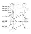
- the pulses obtained from the pulse generator 14 and a reference synchronous signal RS supplied to a terminal 15, as shown in Fig. 6A are supplied to a motor servocontrol circuit 16 to be compared in phase with each other.
- the output resulting from the phase comparison is supplied to the drum motor 11 to control the rotation of the same, manely, the rotation of the rotary magnetic head 2 so that the time point t 1 at which the rotary magnetic head 2 leaves the terminal position for slant tracks on the magnetic tape coincides with a time point of the falling edge of the reference synchronous signal RS, as shown in Fig. 6A.
- the reference synchronous signal RS obtained at the terminal 15 and an information signal for reproducing obtained by selecting the reproducing mode, that is, data DT commanding the direction and speed of tape movement are supplied to both current generating circuits 21 and 22. From the current generating circuit 21, a current which produces through integration in an integrating circuit 23 a portion Ex of a saw-toothed waveform voltage Ess shown in Fig.
- the current generating circuit 22 comprises a decoder 31, six resistant circuits +3R, +2R, OR, -lR, -2R and -3R, a couple of switches 32 and 33, and a couple of monostable multivibrators ( M .M.) 34 and 35.
- the decoder 31 is supplied with the date DT and produces a high level signal at one of output terminals +3Q, +2Q, OQ, -1Q, -2Q and -3Q selected in accordance with one of the "trick" reproducing modes commanded by the data DT and chosen among the three times fast-forward reproducing mode, twice fast-forward reproducing mode, still reproducing mode, reverse reproducing mode, twice fast-reverse reproducing mode and three times fast-reverse reproducing mode.
- Each of the resistant circuits +3R, +2R, OR, -1R, -2R and -3R includes a pair of resistors Ra and Rb and a switch S having contacts a, b and c selectively connected with both one ends of the resistors Ra and Rb and controlled with the high level signal appearing at the corresponding one of the output terminals +3Q, +2Q, 0Q, -1Q, -2Q and -3Q of the decoder 31.
- the contacts a and c are supplied with positive and negative voltages +V and -V, respectively.
- the other ends of the resistors Ra in the resistant circuits +3R, +2R, OR, -1R, -2R and -3R are coupled in common and connected through the switch 32 to the integrating circuit 23, and similarly the other ends of the resistors Rb in the resistant circuits +3R, +2R, OR, -1R, -2R and -3R are coupled in common and connected through the switch 33 to the integrating circuit 23.
- the monostable multivibrators 34 and 35 are supplied with the reference synchronous signal RS from the terminal 15 and triggered at the falling edge of the reference synchronous signal RS, namely, at the time point t 1 whereat the rotary magnetic head 2 leaves the terminal position for slant tracks on the magnetic tape so that output signals M 1 and M 2 rise simultaneously to a high level from a low level at the time point t 1 , as shown in Figs. 6B and 6C, respectively.
- the output signal M 1 of the monostable multivibrator 34 falls to the low level from the high level at the time point t 2 whereat the rotary magnetic head 2 comes into contact with the magnetic tape after a time corresponding to the duration T has elapsed, and the output signal M 2 of the monostable multivibrators 35 falles to the low level from the high level after a time corresponding to a duration Ta has elapsed.
- the duration T is selected to be 0.8 milliseconds, as aforementioned, and the time and the duration Ta is selected to be 0.5 milliseconds.
- the output signal M 1 of the monostable multivibrator 34 is supplied to the switch 32 as a switching control signal to cause the same to be turned on with the high level thereof, and similarly the output signal M 2 of the monostable multivibrator 35 is supplied to the switch 33 as a switching control signal to cause the same to be turned on with the high level thereof.
- the high level signal appears at only the output terminal +3Q of the decoder 31 and therefore the switch S in the resistant circuit +3R is switched to select the contact c and each of the switches S in the resistant circuits +2R, OR, -1R, -2R and -3R is switched to select the contact b.
- the saw-toothed waveform voltage Ess supplied to the compound piezoelectric plate element 13 has the level decreasing with the steep slope during the period Pa including the beginning portion of the period Py and then decreasing further with the gentle slope during the period Pb including the end portion of the period Py, as shown in Fig. 6D, in the fast-forward reproducing mode in the example of the apparatus according to the present invention.
- the swinging movement Ry of the compound piezoelectric plate element 13, which results from the change of the slope of the saw-toothed waveform voltage Ess occuring at the time point t 1 at which the rotary magnetic head 2 leaves the terminal position for slant tracks on the magnetic tape, is increased so as to have the magnitude almost equal to the magnitude of and the phase opposite to the phase of the swinging movement Rx of the compound piezoelectric plate element 13, which results from the change of the slope of the saw-toothed waveform voltage Ess occuring at the time point t 2 at which the rotary magnetic head 2 enters the beginning position for slant tracks on the magnetic tape, as shown in Fig. 6E, in the period Px during which the rotary magnetic head 2 scans the magnetic tape with a appropriately selected ratio of the duration Ta of the period Pa to the duration T of the period Py.
- the swinging movements Ry and Rx of the compound piezoelectric plate element 13 are cancelled out each other, so that the residual swinging movement of the compound piezoelectric plate element 13 caused in the period Px during which the rotary magnetic head 2 scans the magnetic tape is suppressed to have the" magnitude A satisfactorily reduced as shown by means of the positional variation Hp of the rotary magnetic head 2 in the direction of the axis for rotation thereof in Fig. 6F.
- the duration Ta of the period Pa is selected to be equal to 50 to 80 percents of the duration T of the period Py, and the inclination in the period Pb is selected to correspond to 30 to 80 percents of that in the period Pa.
- FIG. 7A to 7E shows the relation between the magnitude A of the residual swinging movement Rz and the duration Ta of the period Pa under the different duration T of the period Py, which is obtained practically in the condition where the frequency of the saw-toothed waveform voltage Ess is 60 Hz, the amplitude of the saw- s toothed waveform voltage Ess is 250 volts and the specific resonant frequency of the ocmpound piezoelectric plate element 13 is 1425 Hz (the specific resonant period is 0.7 milliseconds).
- the magnitude A is referred to as a voltage value which is to bewapplied to the compound piezoelectric plate element 13 for making the same have a deviation of the magnitude A in the static condition.
- the length of the duration Ta by which the residual swinging movement Rz is minimized is varied remarkably in response to variations in the duration T, and in the case where the duration T is longer than 0.8 milliseconds, the residual swinging movement Rz is relatively increased when the length of the duration Ta is deviated slightly from that by which the residual swinging movement Rz is minimized.
- the duration T it is most appropriate to select the duration T to be 0.8 milliseconds and the duration Ta to be about 0.5 milliseconds.
- the residual swinging movement Rz is referred to as the equivalent voltage value of about 10 millivolts, which is reduced to correspond to one eighth of that in the case shown in Fig. 4.
- the high level signal appears at only the output terminal -3Q of the decoder 31 and therefore the switch S in the resistant circuit -3R is switched to select the contact a and each of the switches S in the resistant circuit +2R, oR, -1R, -2R and -3R is switched to select the contact b.
- a current flows from the contact a of the switch S in the resistant circuit -3R to which the positive voltage +V is supplied through both the resistors Ra and Rb in the resistant circuit -3R to the input end of the integrating circuit 23, so that the output voltage of the integrating circuit 23 is steeply increased to form the portion Ea of the saw-toothed waveform voltage Ess having a steeply increasing slope.
- the high level signal appears at only the output terminal OQ or -lQ of the decoder 31 and therefore the switch S in the resistant circuit OR or -1R is switched to select the contact a. Accordingly, in the same manner as the three fast-reverse reproducing mode,-the output voltage of the integrating circuit 23 is steeply increased to form the portion Ea of the saw-toothed waveform voltage Ess having a steeply increasing slope in the period Pa commencing from the time point t 1 with the duration Ta and gently increased to form the portion Eb of the saw-toothed waveform voltage Ess having a gently increasing slope in the period Pb successive to the period Pa.
- the saw-toothed waveform voltage Ess supplied to the compound piezoelectric plate element 13 has the level increasing with the steep slope during the period Pa including the beginning portion of the period Py and then increasing further with the gentle slope during the period Pb including the end portion of the period Py in the fast-reverse, still or reverse reproducing mode in the example of the apparatus according to the present invention.
- the residual swinging movement Rz of the compound piezoelectric plate element 13 caused in the period Px during which the rotary magnetic head 2 scans the magnetic tpe is satisfactorily reduced in the same manner as mentioned above in connection with the fast-forward reproducing mode.
Landscapes
- Adjustment Of The Magnetic Head Position Track Following On Tapes (AREA)
- Television Signal Processing For Recording (AREA)
- Signal Processing Not Specific To The Method Of Recording And Reproducing (AREA)
Priority Applications (1)
| Application Number | Priority Date | Filing Date | Title |
|---|---|---|---|
| AT85100778T ATE39778T1 (de) | 1984-01-27 | 1985-01-25 | Geraet zur erzeugung eines videosignales. |
Applications Claiming Priority (2)
| Application Number | Priority Date | Filing Date | Title |
|---|---|---|---|
| JP13910/84 | 1984-01-27 | ||
| JP59013910A JPS60158781A (ja) | 1984-01-27 | 1984-01-27 | ビデオテ−プレコ−ダ− |
Publications (2)
| Publication Number | Publication Date |
|---|---|
| EP0150828A1 true EP0150828A1 (fr) | 1985-08-07 |
| EP0150828B1 EP0150828B1 (fr) | 1989-01-04 |
Family
ID=11846321
Family Applications (1)
| Application Number | Title | Priority Date | Filing Date |
|---|---|---|---|
| EP85100778A Expired EP0150828B1 (fr) | 1984-01-27 | 1985-01-25 | Appareil pour reproduire un signal vidéo |
Country Status (6)
| Country | Link |
|---|---|
| US (1) | US4698699A (fr) |
| EP (1) | EP0150828B1 (fr) |
| JP (1) | JPS60158781A (fr) |
| AT (1) | ATE39778T1 (fr) |
| AU (1) | AU575902B2 (fr) |
| DE (1) | DE3567300D1 (fr) |
Cited By (1)
| Publication number | Priority date | Publication date | Assignee | Title |
|---|---|---|---|---|
| GB2240658A (en) * | 1990-01-12 | 1991-08-07 | Mitsubishi Electric Corp | A rotating magnetic head for a magnetic recording reproduction system |
Citations (5)
| Publication number | Priority date | Publication date | Assignee | Title |
|---|---|---|---|---|
| US4172265A (en) * | 1977-12-29 | 1979-10-23 | Sony Corporation | Automatic head tracking system |
| US4287538A (en) * | 1978-09-07 | 1981-09-01 | Sony Corporation | Magnetic head tracking control system |
| EP0040066A1 (fr) * | 1980-05-10 | 1981-11-18 | Sony Corporation | Dispositif de réglage de la trace de balayage pour appareils de reproduction magnétique |
| US4319289A (en) * | 1978-03-23 | 1982-03-09 | Ampex Corporation | Movable head automatic position acquisition circuit and method |
| EP0054419A2 (fr) * | 1980-12-13 | 1982-06-23 | Sony Corporation | Dispositif de réglage de la trace de balayage d'un appareil d'enregistrement et de reproduction magnétique |
Family Cites Families (11)
| Publication number | Priority date | Publication date | Assignee | Title |
|---|---|---|---|---|
| GB1560023A (en) * | 1976-10-05 | 1980-01-30 | Sony Corp | Automatic magnetic-head scan tracking arrangements |
| JPS54307U (fr) * | 1977-06-04 | 1979-01-05 | ||
| JPS5665332A (en) * | 1979-10-29 | 1981-06-03 | Sony Corp | Magnetic recording and reproducing device |
| JPS56127925A (en) * | 1980-03-13 | 1981-10-07 | Sony Corp | Tracking device of magnetic head |
| JPS5727421A (en) * | 1980-07-23 | 1982-02-13 | Sony Corp | Track following device |
| JPS5766525A (en) * | 1980-10-09 | 1982-04-22 | Matsushita Electric Ind Co Ltd | Driving device for electromechanical transducer |
| US4550351A (en) * | 1982-03-31 | 1985-10-29 | Rca Corporation | Adaptive automatic scan tracking system |
| US4471392A (en) * | 1982-03-31 | 1984-09-11 | Rca Corporation | Automatic scan tracking with ringing control |
| JPS58171715A (ja) * | 1982-04-02 | 1983-10-08 | Sony Corp | 再生装置 |
| JPS6010414A (ja) * | 1983-06-30 | 1985-01-19 | Nec Home Electronics Ltd | 偏向電圧の整形回路 |
| JPS6069814A (ja) * | 1983-09-22 | 1985-04-20 | Canon Inc | 回転ヘッド型再生装置 |
-
1984
- 1984-01-27 JP JP59013910A patent/JPS60158781A/ja active Pending
-
1985
- 1985-01-22 AU AU37976/85A patent/AU575902B2/en not_active Ceased
- 1985-01-24 US US06/694,300 patent/US4698699A/en not_active Expired - Fee Related
- 1985-01-25 EP EP85100778A patent/EP0150828B1/fr not_active Expired
- 1985-01-25 DE DE8585100778T patent/DE3567300D1/de not_active Expired
- 1985-01-25 AT AT85100778T patent/ATE39778T1/de active
Patent Citations (5)
| Publication number | Priority date | Publication date | Assignee | Title |
|---|---|---|---|---|
| US4172265A (en) * | 1977-12-29 | 1979-10-23 | Sony Corporation | Automatic head tracking system |
| US4319289A (en) * | 1978-03-23 | 1982-03-09 | Ampex Corporation | Movable head automatic position acquisition circuit and method |
| US4287538A (en) * | 1978-09-07 | 1981-09-01 | Sony Corporation | Magnetic head tracking control system |
| EP0040066A1 (fr) * | 1980-05-10 | 1981-11-18 | Sony Corporation | Dispositif de réglage de la trace de balayage pour appareils de reproduction magnétique |
| EP0054419A2 (fr) * | 1980-12-13 | 1982-06-23 | Sony Corporation | Dispositif de réglage de la trace de balayage d'un appareil d'enregistrement et de reproduction magnétique |
Cited By (3)
| Publication number | Priority date | Publication date | Assignee | Title |
|---|---|---|---|---|
| GB2240658A (en) * | 1990-01-12 | 1991-08-07 | Mitsubishi Electric Corp | A rotating magnetic head for a magnetic recording reproduction system |
| GB2240658B (en) * | 1990-01-12 | 1994-04-06 | Mitsubishi Electric Corp | A rotating magnetic head for a magnetic recording/reproduction system |
| US5313347A (en) * | 1990-01-12 | 1994-05-17 | Mitsubishi Denki Kabushiki Kaisha | Rotating magnetic head for a magnetic recording reproduction system |
Also Published As
| Publication number | Publication date |
|---|---|
| US4698699A (en) | 1987-10-06 |
| AU3797685A (en) | 1985-08-01 |
| AU575902B2 (en) | 1988-08-11 |
| ATE39778T1 (de) | 1989-01-15 |
| DE3567300D1 (en) | 1989-02-09 |
| JPS60158781A (ja) | 1985-08-20 |
| EP0150828B1 (fr) | 1989-01-04 |
Similar Documents
| Publication | Publication Date | Title |
|---|---|---|
| US4255768A (en) | Tracking control apparatus for a rotary head, variable speed signal reproducing system | |
| US4148082A (en) | Tracking control apparatus | |
| US4143405A (en) | Automatic head scan tracking system | |
| US4233637A (en) | Rotating magnetic head piezo-electric assembly and drive circuitry for video tape recorder | |
| US4636874A (en) | System for reproducing information signals on a magnetic tape which incrementally adjusts, in a plurality of steps the speed of the magnetic tape and the positioning and rotational speed of the magnetic head upon a change of mode | |
| CA1119293A (fr) | Lecteur de signaux video | |
| US4203140A (en) | Helical scan VTR with deflectable head | |
| US4141048A (en) | Video signal recording and/or reproducing apparatus | |
| GB1573064A (en) | Magnetic reproducing systems | |
| JPS6213872B2 (fr) | ||
| GB2063518A (en) | Head positioning signal generating apparatuses for helical scan type video tape recorders | |
| GB2032728A (en) | Magnetic recording and reproducing apparatus | |
| GB1574985A (en) | Video signal reproducing apparatus | |
| US4314284A (en) | Video head deflection apparatus for special motion reproduction by helical scan VTR | |
| EP0043739B1 (fr) | Système d'alignement | |
| EP0083958B1 (fr) | Procédé et appareil pour l'enregistrement de trames isolées sur bande vidéo | |
| US4720753A (en) | Auto tracking apparatus for scanning tracks with controllable head displacement | |
| EP0150828B1 (fr) | Appareil pour reproduire un signal vidéo | |
| JPS6412007B2 (fr) | ||
| US4288824A (en) | Deflectable transducer mounting with damper for video signal reproducing apparatus | |
| JPS6341470B2 (fr) | ||
| US4470078A (en) | Pulse driven control circuit for moving a transducer across a rotary recording medium of pulses applied thereto | |
| KR880000323B1 (ko) | 자기재생장치에서의 트래킹(tracking)방식 | |
| GB2053509A (en) | Tracking system for video recorders/reproducers | |
| JPS5918763B2 (ja) | 記録再生機 |
Legal Events
| Date | Code | Title | Description |
|---|---|---|---|
| PUAI | Public reference made under article 153(3) epc to a published international application that has entered the european phase |
Free format text: ORIGINAL CODE: 0009012 |
|
| AK | Designated contracting states |
Designated state(s): AT DE FR GB NL |
|
| 17P | Request for examination filed |
Effective date: 19860116 |
|
| 17Q | First examination report despatched |
Effective date: 19870428 |
|
| GRAA | (expected) grant |
Free format text: ORIGINAL CODE: 0009210 |
|
| AK | Designated contracting states |
Kind code of ref document: B1 Designated state(s): AT DE FR GB NL |
|
| REF | Corresponds to: |
Ref document number: 39778 Country of ref document: AT Date of ref document: 19890115 Kind code of ref document: T |
|
| REF | Corresponds to: |
Ref document number: 3567300 Country of ref document: DE Date of ref document: 19890209 |
|
| ET | Fr: translation filed | ||
| PLBE | No opposition filed within time limit |
Free format text: ORIGINAL CODE: 0009261 |
|
| STAA | Information on the status of an ep patent application or granted ep patent |
Free format text: STATUS: NO OPPOSITION FILED WITHIN TIME LIMIT |
|
| 26N | No opposition filed | ||
| PGFP | Annual fee paid to national office [announced via postgrant information from national office to epo] |
Ref country code: FR Payment date: 19950110 Year of fee payment: 11 |
|
| PGFP | Annual fee paid to national office [announced via postgrant information from national office to epo] |
Ref country code: GB Payment date: 19950117 Year of fee payment: 11 |
|
| PGFP | Annual fee paid to national office [announced via postgrant information from national office to epo] |
Ref country code: DE Payment date: 19950121 Year of fee payment: 11 |
|
| PGFP | Annual fee paid to national office [announced via postgrant information from national office to epo] |
Ref country code: AT Payment date: 19950126 Year of fee payment: 11 |
|
| PGFP | Annual fee paid to national office [announced via postgrant information from national office to epo] |
Ref country code: NL Payment date: 19950131 Year of fee payment: 11 |
|
| PG25 | Lapsed in a contracting state [announced via postgrant information from national office to epo] |
Ref country code: GB Effective date: 19960125 Ref country code: AT Effective date: 19960125 |
|
| PG25 | Lapsed in a contracting state [announced via postgrant information from national office to epo] |
Ref country code: NL Effective date: 19960801 |
|
| GBPC | Gb: european patent ceased through non-payment of renewal fee |
Effective date: 19960125 |
|
| PG25 | Lapsed in a contracting state [announced via postgrant information from national office to epo] |
Ref country code: FR Effective date: 19960930 |
|
| NLV4 | Nl: lapsed or anulled due to non-payment of the annual fee |
Effective date: 19960801 |
|
| PG25 | Lapsed in a contracting state [announced via postgrant information from national office to epo] |
Ref country code: DE Effective date: 19961001 |
|
| REG | Reference to a national code |
Ref country code: FR Ref legal event code: ST |