EP0150830A2 - Véhicule transporteur à commande par levier - Google Patents
Véhicule transporteur à commande par levier Download PDFInfo
- Publication number
- EP0150830A2 EP0150830A2 EP85100781A EP85100781A EP0150830A2 EP 0150830 A2 EP0150830 A2 EP 0150830A2 EP 85100781 A EP85100781 A EP 85100781A EP 85100781 A EP85100781 A EP 85100781A EP 0150830 A2 EP0150830 A2 EP 0150830A2
- Authority
- EP
- European Patent Office
- Prior art keywords
- drawbar
- spring means
- drive wheel
- variable
- guided conveyor
- Prior art date
- Legal status (The legal status is an assumption and is not a legal conclusion. Google has not performed a legal analysis and makes no representation as to the accuracy of the status listed.)
- Granted
Links
Images

Classifications
-
- B—PERFORMING OPERATIONS; TRANSPORTING
- B66—HOISTING; LIFTING; HAULING
- B66F—HOISTING, LIFTING, HAULING OR PUSHING, NOT OTHERWISE PROVIDED FOR, e.g. DEVICES WHICH APPLY A LIFTING OR PUSHING FORCE DIRECTLY TO THE SURFACE OF A LOAD
- B66F9/00—Devices for lifting or lowering bulky or heavy goods for loading or unloading purposes
- B66F9/06—Devices for lifting or lowering bulky or heavy goods for loading or unloading purposes movable, with their loads, on wheels or the like, e.g. fork-lift trucks
- B66F9/075—Constructional features or details
- B66F9/07572—Propulsion arrangements
-
- B—PERFORMING OPERATIONS; TRANSPORTING
- B60—VEHICLES IN GENERAL
- B60G—VEHICLE SUSPENSION ARRANGEMENTS
- B60G17/00—Resilient suspensions having means for adjusting the spring or vibration-damper characteristics, for regulating the distance between a supporting surface and a sprung part of vehicle or for locking suspension during use to meet varying vehicular or surface conditions, e.g. due to speed or load
- B60G17/02—Spring characteristics, e.g. mechanical springs and mechanical adjusting means
-
- B—PERFORMING OPERATIONS; TRANSPORTING
- B62—LAND VEHICLES FOR TRAVELLING OTHERWISE THAN ON RAILS
- B62B—HAND-PROPELLED VEHICLES, e.g. HAND CARTS OR PERAMBULATORS; SLEDGES
- B62B3/00—Hand carts having more than one axis carrying transport wheels; Steering devices therefor; Equipment therefor
- B62B3/04—Hand carts having more than one axis carrying transport wheels; Steering devices therefor; Equipment therefor involving means for grappling or securing in place objects to be carried; Loading or unloading equipment
- B62B3/06—Hand carts having more than one axis carrying transport wheels; Steering devices therefor; Equipment therefor involving means for grappling or securing in place objects to be carried; Loading or unloading equipment for simply clearing the load from the ground
- B62B3/0612—Hand carts having more than one axis carrying transport wheels; Steering devices therefor; Equipment therefor involving means for grappling or securing in place objects to be carried; Loading or unloading equipment for simply clearing the load from the ground power operated
-
- B—PERFORMING OPERATIONS; TRANSPORTING
- B66—HOISTING; LIFTING; HAULING
- B66F—HOISTING, LIFTING, HAULING OR PUSHING, NOT OTHERWISE PROVIDED FOR, e.g. DEVICES WHICH APPLY A LIFTING OR PUSHING FORCE DIRECTLY TO THE SURFACE OF A LOAD
- B66F9/00—Devices for lifting or lowering bulky or heavy goods for loading or unloading purposes
- B66F9/06—Devices for lifting or lowering bulky or heavy goods for loading or unloading purposes movable, with their loads, on wheels or the like, e.g. fork-lift trucks
- B66F9/075—Constructional features or details
- B66F9/07586—Suspension or mounting of wheels on chassis
-
- B—PERFORMING OPERATIONS; TRANSPORTING
- B60—VEHICLES IN GENERAL
- B60G—VEHICLE SUSPENSION ARRANGEMENTS
- B60G2300/00—Indexing codes relating to the type of vehicle
- B60G2300/02—Trucks; Load vehicles
- B60G2300/022—Fork lift trucks, Clark
Definitions
- the invention relates to a drawbar-steered conveyor, in particular a pedestrian pallet truck or a pedestrian stacker, in which a steerable, in particular hub motor-driven, drive wheel is arranged between two lateral support wheels, the drive wheel is pressed into ground engagement by spring means, and the pretension of the spring means is variable by a pretensioner as a function of an operating parameter.
- Such a conveyor is known from DE-OS 31 06 027.
- a reduction in the ground contact pressure is brought about on the one hand with increasing load size.
- a reduction in the ground contact pressure is brought about. This is to ensure that the stability of the conveyor against tilting is improved. It has been shown that the known device does not work optimally under all operating conditions. So it proves to be particularly unsuitable that the ground contact pressure is greatest when the conveyor is not loaded. This means that the steering is stiff for the operator when the device is not loaded, without any recognizable other advantage.
- braking is preferably effected on the steerable drive wheel, since this wheel is generally best suited for braking as a result of its larger diameter compared to the lateral support wheels and compared to other support wheels, for example below the lifting fork.
- the ground contact pressure decreases with increasing load and with increasing lifting height, the effectiveness of the braking, which depends on the contact with the ground, can be called into question at high load and / or high lifting height.
- the invention has for its object to provide in a conveyor device of the generic type that the result from the low ground contact pressure advantage of easy maneuverability for the operator is always guaranteed when a high ground contact pressure is not required from other points of view.
- the ground contact pressure necessary for the transmission of the braking force to the road surface should in any case be guaranteed when braking.
- ground contact pressure is dimensioned so that it is usually sufficient for normal operation when driving on level ground. So the ground contact pressure is set so that it is a certain amount of safety above the value at which the wheel would slip.
- This ground contact pressure reserve would now, for. B. at the transition from the plane to a slope, can be reduced; but then an increase in the ground contact pressure is brought about by the simultaneously increasing load torque of the drive motor. This ensures that the ground contact pressure reserve does not fall below a certain minimum value during operation despite different drive requirements.
- the drive torque of the drive motor is a measure of the inclination that must be overcome by the conveyor.
- This drive torque can also be increased depending on, for example, a towing load coupled to the conveyor. Such a towing load may also result in the need to increase the ground contact pressure.
- the measure of claim 3 therefore represents a preferred possibility for determining road inclination and other situations in which an increased ground contact pressure is required.
- a NeHe laser or a gas discharge lamp serves as the light source.
- the bumps can be determined either with autocollimation or transmission or directed or diffuse reflection. If the system detects an error, an error evaluation is carried out via evaluation electronics.
- problem-specific error evaluations can be implemented - starting with a simple yes / no statement to a complex error analysis using a microprocessor.
- a microprocessor For example, reference is made to the automatic surface inspection systems from Sick Optik, Elektronik.
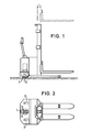
- 1 and 2 show a pedestrian-controlled electric stacker with center drive.
- the steerable drive wheel 1 is suspended in the vertical direction in the vehicle frame.
- the two lateral support wheels 2 are designed as castors with an axis of rotation trailing with respect to the pivot axis. They are rigidly fixed in the vehicle frame in the vertical direction.
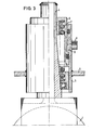
- Fig. 3 shows the storage of the steerable drive wheel with hub drive in the vehicle frame.
- the bearing 3 for the steering shaft 4 of the drive wheel 1 is connected to the drive part of the vehicle frame via the frame part 5.
- the bearing point 3 is designed as a hydraulic cylinder. This lot takes up the upper support 6 for the spring 7 as a piston. By filling the cylinder space 8 with pressure oil through the connecting piece 9, the installation space for the spring 7 can be reduced in height.
- Fig. 4 shows the circuit arrangement for the automatic increase of the bias of the spring 7 when actuating the brake parts.
- the switch 10 is operatively connected to the brake actuators of the vehicle.
- the switch 10 When the brakes are applied, the switch 10 is closed; the valve 11 is opened electromagnetically, so that the hydraulic accumulator 12 supplies the cylinder chamber 8 with pressure oil, as a result of which the installation space of the spring 7 is shortened.
- the switch 10 At the end of the braking process, the switch 10 is opened and the cylinder space 8 is emptied again.
- the switch 13 is part of the lifting hydraulic system of the vehicle and is operatively connected to it in such a way that it is closed each time the control element is actuated to lift the load-carrying means.
- the motor 14 for the lifting hydraulics and the hydraulic pump 15 - likewise components of the lifting hydraulic system of the vehicle - are put into operation, so that in addition to the lifting of the load-carrying means, the pressure accumulator 12 is also refilled with each lifting operation.
- Line 16 leads to the hydraulic lifting system of the vehicle.
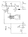
- Fig. 5 shows the circuit arrangement if there is also the possibility that the pedestrian increases the bias of the spring element by pressing a button.
- the valve 11 When the button 18 is actuated, the valve 11 is opened via the switching element 19 and so that the spring element 7 is preloaded to a greater extent, ie. H. the wheel pressure increases. It is conceivable that the filling of the cylinder space 8 is varied by the duty cycle and thus enables a continuously variable increase in wheel pressure.
- the switching member 20 is communicated with the Hubh y hydraulics of the vehicle so operatively connected that it is open at each actuation of the actuator for lowering the load receiving means. This causes the switching element 19 to open and, as a result, the cylinder space 8 to be emptied. In this way, the increased wheel pressure is automatically reduced each time the load is deposited, if it has not already been reset before, for example, by releasing the brake linkage.
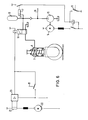
- Fig. 6 shows the switching arrangement for increasing the wheel pressure at high current in the traction motor circuit (when driving uphill and driving over obstacles).
- the shunt 21 is in the circuit of the vehicle drive motors 22.
- a predetermined driving force ie current of the drive motor is exceeded
Landscapes
- Engineering & Computer Science (AREA)
- Transportation (AREA)
- Structural Engineering (AREA)
- Mechanical Engineering (AREA)
- Civil Engineering (AREA)
- Life Sciences & Earth Sciences (AREA)
- Geology (AREA)
- Chemical & Material Sciences (AREA)
- Combustion & Propulsion (AREA)
- Handcart (AREA)
- Forklifts And Lifting Vehicles (AREA)
Priority Applications (1)
| Application Number | Priority Date | Filing Date | Title |
|---|---|---|---|
| AT85100781T ATE41370T1 (de) | 1984-01-25 | 1985-01-25 | Deichselgelenktes foerdergeraet. |
Applications Claiming Priority (2)
| Application Number | Priority Date | Filing Date | Title |
|---|---|---|---|
| DE3402495 | 1984-01-25 | ||
| DE19843402495 DE3402495A1 (de) | 1984-01-25 | 1984-01-25 | Deichselgelenktes foerdergeraet |
Publications (3)
| Publication Number | Publication Date |
|---|---|
| EP0150830A2 true EP0150830A2 (fr) | 1985-08-07 |
| EP0150830A3 EP0150830A3 (en) | 1986-07-23 |
| EP0150830B1 EP0150830B1 (fr) | 1989-03-15 |
Family
ID=6225861
Family Applications (1)
| Application Number | Title | Priority Date | Filing Date |
|---|---|---|---|
| EP85100781A Expired EP0150830B1 (fr) | 1984-01-25 | 1985-01-25 | Véhicule transporteur à commande par levier |
Country Status (4)
| Country | Link |
|---|---|
| US (1) | US4598784A (fr) |
| EP (1) | EP0150830B1 (fr) |
| AT (1) | ATE41370T1 (fr) |
| DE (2) | DE3402495A1 (fr) |
Cited By (11)
| Publication number | Priority date | Publication date | Assignee | Title |
|---|---|---|---|---|
| FR2606765A1 (fr) * | 1986-11-13 | 1988-05-20 | Loc Manutention | Mecanisme repartiteur d'appui pour chariots de manutention et de levage notamment les transpalettes et les gerbeurs |
| US4750579A (en) * | 1985-07-08 | 1988-06-14 | Aktiebolaget Bygg-Och Transportekonomi (Bt) | Arrangement in industrial trucks |
| DE3904798A1 (de) * | 1989-02-17 | 1990-08-30 | Wagner Foerdertechnik | Hubwagen mit einer in vertikaler richtung federbelastet vorgespannten antriebseinheit |
| EP0583546A1 (fr) * | 1992-08-14 | 1994-02-23 | Jungheinrich Aktiengesellschaft | Chariot de manutention, en particulier véhicule sans conducteur |
| FR2714899A1 (fr) * | 1994-01-10 | 1995-07-13 | Sefac Equipement | Dispositif de levage mobile, notamment destiné au levage de véhicules. |
| FR2725437A1 (fr) | 1994-09-14 | 1996-04-12 | Jungheinrich Ag | Chariot de manutention a roue d'entrainement precontrainte vers le sol |
| FR2788482A1 (fr) * | 1999-01-15 | 2000-07-21 | Fenwick Linde | Chariot elevateur |
| DE19753412C2 (de) * | 1997-12-02 | 2001-03-22 | Jungheinrich Ag | Gabelhubwagen mit verstellbarer Stützrolle |
| WO2012145252A1 (fr) * | 2011-04-19 | 2012-10-26 | Newell Gregory | Ensemble de propulsion de transpalette à main |
| KR101223382B1 (ko) * | 2007-09-19 | 2013-01-17 | 에프. 호프만-라 로슈 아게 | 살균 란셋을 위한 레이저에 의한 포일 결합 |
| US9623891B2 (en) | 2011-04-19 | 2017-04-18 | Power Handling, Incorporated | Pallet jack power assembly |
Families Citing this family (11)
| Publication number | Priority date | Publication date | Assignee | Title |
|---|---|---|---|---|
| DE3710757A1 (de) * | 1987-03-31 | 1988-10-20 | Genkinger Hermann Gmbh | Gabelhubwagen |
| DE102004019072A1 (de) * | 2004-04-20 | 2005-11-17 | Om Carrelli Elevatori S.P.A. | Flurförderzeug, insbesondere Gabelhubwagen |
| DE102005032263A1 (de) * | 2005-07-11 | 2007-01-18 | Jungheinrich Aktiengesellschaft | Vier-Rad-Fahrwerk für ein Flurförderzeug, vorzugsweise einen Gegengewichtsstapler |
| DE102006024117A1 (de) * | 2006-05-22 | 2007-11-29 | Linde Material Handling Gmbh | Lagerung der Antriebseinheit eines Flurförderzeugs |
| AU2008236616A1 (en) * | 2007-04-09 | 2008-10-16 | Scidose, Llc | Combinations of statins and anti-obesity agent |
| BR112012013774B1 (pt) * | 2009-12-10 | 2020-09-08 | Gerhard Finkbeiner | Dispositivo de içamento e método para teste e monitoramento desse dispositivo de içamento |
| DE102012004290A1 (de) * | 2012-03-02 | 2013-09-05 | Wabco Gmbh | Antriebsachsen-Achslastbeeinflussung bei Fahrzeugzügen |
| CN103879926B (zh) * | 2014-03-27 | 2017-05-03 | 江苏华宏科技股份有限公司 | 移动式汽车提升机 |
| US10315900B2 (en) * | 2014-04-01 | 2019-06-11 | The Raymond Corporation | Caster wheel with constant force mechanism |
| US9593003B2 (en) * | 2014-04-01 | 2017-03-14 | The Raymond Corporation | Caster wheel with constant force mechanism |
| US9533863B2 (en) * | 2014-10-23 | 2017-01-03 | Jungheinrich Aktiengesellschaft | Industrial truck |
Family Cites Families (12)
| Publication number | Priority date | Publication date | Assignee | Title |
|---|---|---|---|---|
| DE625881C (de) * | 1934-04-30 | 1936-02-17 | Saurer Ag Adolph | Vorrichtung zur AEnderung des Belastungsverhaeltnisses der Treibachse und der mit ihr durch die Tragfedern verbundenen Schleppachse, insbesondere fuer Kraftfahrzeuge |
| DE919517C (de) * | 1953-02-25 | 1954-10-25 | Hans Still Ag | Federspannvorrichtung fuer Fahrzeuge |
| US2864453A (en) * | 1956-06-29 | 1958-12-16 | Gen Motors Corp | Weight-shifting apparatus for tandem axle vehicles |
| DE1183813B (de) * | 1957-01-18 | 1964-12-17 | Italiana Magneti Marelli Soc P | Bremsanlage fuer Fahrzeuge, insbesondere Kraftfahrzeuge, mit drei oder mehr Achsen |
| FR1539003A (fr) * | 1967-05-09 | 1968-09-13 | Appareil de manutention automoteur | |
| US3537715A (en) * | 1968-02-19 | 1970-11-03 | Robert R Gualdoni | Snubbing means for automotive vehicle |
| DE2758956A1 (de) * | 1976-07-15 | 1979-05-10 | Aspro Inc | Vorrichtung zur steuerung der zugkraft eines motorfahrzeuges |
| US4186813A (en) * | 1978-04-03 | 1980-02-05 | Rolair Systems, Inc. | Steerable drive unit for transporter |
| AU554309B2 (en) * | 1980-08-06 | 1986-08-14 | Barry John Schultz | Vehicular suspension |
| US4393959A (en) * | 1980-12-10 | 1983-07-19 | Allis-Chalmers Corporation | Hydraulic stabilizer for axle on mast lift vehicle |
| DE3106027C2 (de) * | 1981-02-19 | 1985-11-28 | Jungheinrich Unternehmensverwaltung Kg, 2000 Hamburg | Hublader mit einem höhenausgleichbaren Radnabenantrieb |
| JPS58174007A (ja) * | 1982-04-06 | 1983-10-13 | Nissan Motor Co Ltd | 自動車高調整装置 |
-
1984
- 1984-01-25 DE DE19843402495 patent/DE3402495A1/de not_active Ceased
-
1985
- 1985-01-16 US US06/692,362 patent/US4598784A/en not_active Expired - Lifetime
- 1985-01-25 AT AT85100781T patent/ATE41370T1/de not_active IP Right Cessation
- 1985-01-25 EP EP85100781A patent/EP0150830B1/fr not_active Expired
- 1985-01-25 DE DE8585100781T patent/DE3568742D1/de not_active Expired
Cited By (13)
| Publication number | Priority date | Publication date | Assignee | Title |
|---|---|---|---|---|
| US4750579A (en) * | 1985-07-08 | 1988-06-14 | Aktiebolaget Bygg-Och Transportekonomi (Bt) | Arrangement in industrial trucks |
| US4805710A (en) * | 1985-07-08 | 1989-02-21 | Aktiebolaget Bygg-Och Transportekonomi (Bt) | Arrangement in industrial trucks |
| FR2606765A1 (fr) * | 1986-11-13 | 1988-05-20 | Loc Manutention | Mecanisme repartiteur d'appui pour chariots de manutention et de levage notamment les transpalettes et les gerbeurs |
| DE3904798A1 (de) * | 1989-02-17 | 1990-08-30 | Wagner Foerdertechnik | Hubwagen mit einer in vertikaler richtung federbelastet vorgespannten antriebseinheit |
| EP0583546A1 (fr) * | 1992-08-14 | 1994-02-23 | Jungheinrich Aktiengesellschaft | Chariot de manutention, en particulier véhicule sans conducteur |
| FR2714899A1 (fr) * | 1994-01-10 | 1995-07-13 | Sefac Equipement | Dispositif de levage mobile, notamment destiné au levage de véhicules. |
| FR2725437A1 (fr) | 1994-09-14 | 1996-04-12 | Jungheinrich Ag | Chariot de manutention a roue d'entrainement precontrainte vers le sol |
| DE19753412C2 (de) * | 1997-12-02 | 2001-03-22 | Jungheinrich Ag | Gabelhubwagen mit verstellbarer Stützrolle |
| FR2788482A1 (fr) * | 1999-01-15 | 2000-07-21 | Fenwick Linde | Chariot elevateur |
| KR101223382B1 (ko) * | 2007-09-19 | 2013-01-17 | 에프. 호프만-라 로슈 아게 | 살균 란셋을 위한 레이저에 의한 포일 결합 |
| WO2012145252A1 (fr) * | 2011-04-19 | 2012-10-26 | Newell Gregory | Ensemble de propulsion de transpalette à main |
| US8752657B2 (en) | 2011-04-19 | 2014-06-17 | Power Handling, Incorporated | Pallet jack power assembly |
| US9623891B2 (en) | 2011-04-19 | 2017-04-18 | Power Handling, Incorporated | Pallet jack power assembly |
Also Published As
| Publication number | Publication date |
|---|---|
| EP0150830A3 (en) | 1986-07-23 |
| DE3402495A1 (de) | 1985-07-25 |
| DE3568742D1 (en) | 1989-04-20 |
| US4598784A (en) | 1986-07-08 |
| ATE41370T1 (de) | 1989-04-15 |
| EP0150830B1 (fr) | 1989-03-15 |
Similar Documents
| Publication | Publication Date | Title |
|---|---|---|
| EP0150830B1 (fr) | Véhicule transporteur à commande par levier | |
| DE3904798C2 (fr) | ||
| DE69807098T3 (de) | Produktivitätspaket | |
| DE102008054085B4 (de) | Flurförderzeug | |
| EP0465838B1 (fr) | Véhicule porte-charge avec securité contre le basculement | |
| DE3816486C2 (fr) | ||
| DE2913685A1 (de) | Lastentragende fahrzeuge | |
| DE2545427C3 (fr) | ||
| DE69810562T2 (de) | Vorrichtung und Verfahren zur Rollbegrenzung einer Hinterachse eines Nutzfahrzeuges | |
| EP1371603B1 (fr) | Procédé de contrôle d'au moins un mouvement d'un chariot de manutention | |
| DE2242109C3 (de) | Lastkraftwagen mit kippbarem Führerhaus, sowie Bedienungsvorrichtung dazu | |
| EP0236804B1 (fr) | Procédé pour signaler la charge et la surcharge | |
| DE4432620C2 (de) | Flurförderzeug | |
| DE4226936C1 (de) | Flurförderzeug, insbesondere fahrerloses Fahrzeug | |
| EP2450305B1 (fr) | Chariot de manutention doté d'un capteur de déformation dans le cylindre d'inclinaison | |
| DE1927579A1 (de) | Vorrichtung an Hubstaplern | |
| DE4004773C2 (de) | Verfahren zum Bremsen eines über den Fahrantrieb und den Fahrantriebsmotor abbremsbaren Fahrzeuges und Steuereinrichtung dafür | |
| DE102005014907A1 (de) | Niederhub-Flurförderzeug | |
| DE19840151A1 (de) | Abstützstruktur für Radfahrzeuge | |
| DE102020129272A1 (de) | Fahrerloses Transportfahrzeug | |
| DE3324401C2 (fr) | ||
| DE102020125036B3 (de) | Arbeitsmaschine | |
| DE102020104808A1 (de) | Fahrerloses Transportfahrzeug mit einer einen Gewindespindeltrieb umfassenden Hubvorrichtung | |
| DE102019131224A1 (de) | Moduleinheit zum Aufbau eines Routenzugs zum Transportieren von Gegenständen, Routenzug mit einer Anzahl von derartigen Moduleinheiten sowie Verfahren zum Betreiben einer solchen Moduleinheit | |
| DE19646663B4 (de) | Flurförderzeug mit einer Bremsvorrichtung |
Legal Events
| Date | Code | Title | Description |
|---|---|---|---|
| PUAI | Public reference made under article 153(3) epc to a published international application that has entered the european phase |
Free format text: ORIGINAL CODE: 0009012 |
|
| AK | Designated contracting states |
Designated state(s): AT BE DE FR GB IT NL SE |
|
| PUAL | Search report despatched |
Free format text: ORIGINAL CODE: 0009013 |
|
| AK | Designated contracting states |
Kind code of ref document: A3 Designated state(s): AT BE DE FR GB IT NL SE |
|
| 17P | Request for examination filed |
Effective date: 19861121 |
|
| 17Q | First examination report despatched |
Effective date: 19871217 |
|
| GRAA | (expected) grant |
Free format text: ORIGINAL CODE: 0009210 |
|
| AK | Designated contracting states |
Kind code of ref document: B1 Designated state(s): AT BE DE FR GB IT NL SE |
|
| REF | Corresponds to: |
Ref document number: 41370 Country of ref document: AT Date of ref document: 19890415 Kind code of ref document: T |
|
| ITF | It: translation for a ep patent filed | ||
| REF | Corresponds to: |
Ref document number: 3568742 Country of ref document: DE Date of ref document: 19890420 |
|
| GBT | Gb: translation of ep patent filed (gb section 77(6)(a)/1977) | ||
| ET | Fr: translation filed | ||
| PLBE | No opposition filed within time limit |
Free format text: ORIGINAL CODE: 0009261 |
|
| STAA | Information on the status of an ep patent application or granted ep patent |
Free format text: STATUS: NO OPPOSITION FILED WITHIN TIME LIMIT |
|
| 26N | No opposition filed | ||
| ITTA | It: last paid annual fee | ||
| EAL | Se: european patent in force in sweden |
Ref document number: 85100781.5 |
|
| BECH | Be: change of holder |
Free format text: 950823 *STEINBOCK BOSS G.M.B.H. FORDERTECHNIK |
|
| NLS | Nl: assignments of ep-patents |
Owner name: STEINBOCK BOSS GMBH FOERDERTECHNIK |
|
| NLT1 | Nl: modifications of names registered in virtue of documents presented to the patent office pursuant to art. 16 a, paragraph 1 |
Owner name: STEINBOCK BOSS GMBH |
|
| PGFP | Annual fee paid to national office [announced via postgrant information from national office to epo] |
Ref country code: GB Payment date: 19981026 Year of fee payment: 15 |
|
| PGFP | Annual fee paid to national office [announced via postgrant information from national office to epo] |
Ref country code: FR Payment date: 19981112 Year of fee payment: 15 |
|
| PGFP | Annual fee paid to national office [announced via postgrant information from national office to epo] |
Ref country code: SE Payment date: 19981203 Year of fee payment: 15 |
|
| PGFP | Annual fee paid to national office [announced via postgrant information from national office to epo] |
Ref country code: AT Payment date: 19990112 Year of fee payment: 15 |
|
| PGFP | Annual fee paid to national office [announced via postgrant information from national office to epo] |
Ref country code: BE Payment date: 19990120 Year of fee payment: 15 |
|
| PGFP | Annual fee paid to national office [announced via postgrant information from national office to epo] |
Ref country code: NL Payment date: 19990129 Year of fee payment: 15 |
|
| PGFP | Annual fee paid to national office [announced via postgrant information from national office to epo] |
Ref country code: DE Payment date: 19990205 Year of fee payment: 15 |
|
| PG25 | Lapsed in a contracting state [announced via postgrant information from national office to epo] |
Ref country code: GB Free format text: LAPSE BECAUSE OF NON-PAYMENT OF DUE FEES Effective date: 20000125 Ref country code: AT Free format text: LAPSE BECAUSE OF NON-PAYMENT OF DUE FEES Effective date: 20000125 |
|
| PG25 | Lapsed in a contracting state [announced via postgrant information from national office to epo] |
Ref country code: SE Free format text: LAPSE BECAUSE OF NON-PAYMENT OF DUE FEES Effective date: 20000126 |
|
| PG25 | Lapsed in a contracting state [announced via postgrant information from national office to epo] |
Ref country code: BE Free format text: LAPSE BECAUSE OF NON-PAYMENT OF DUE FEES Effective date: 20000131 |
|
| BERE | Be: lapsed |
Owner name: STEINBOCK BOSS G.M.B.H. FORDERTECHNIK Effective date: 20000131 |
|
| PG25 | Lapsed in a contracting state [announced via postgrant information from national office to epo] |
Ref country code: NL Free format text: LAPSE BECAUSE OF NON-PAYMENT OF DUE FEES Effective date: 20000801 |
|
| EUG | Se: european patent has lapsed |
Ref document number: 85100781.5 |
|
| GBPC | Gb: european patent ceased through non-payment of renewal fee |
Effective date: 20000125 |
|
| PG25 | Lapsed in a contracting state [announced via postgrant information from national office to epo] |
Ref country code: FR Free format text: LAPSE BECAUSE OF NON-PAYMENT OF DUE FEES Effective date: 20000929 |
|
| NLV4 | Nl: lapsed or anulled due to non-payment of the annual fee |
Effective date: 20000801 |
|
| PG25 | Lapsed in a contracting state [announced via postgrant information from national office to epo] |
Ref country code: DE Free format text: LAPSE BECAUSE OF NON-PAYMENT OF DUE FEES Effective date: 20001101 |
|
| REG | Reference to a national code |
Ref country code: FR Ref legal event code: ST |