EP0150847A2 - Beleuchtungssteuerausstattung - Google Patents
Beleuchtungssteuerausstattung Download PDFInfo
- Publication number
- EP0150847A2 EP0150847A2 EP85100945A EP85100945A EP0150847A2 EP 0150847 A2 EP0150847 A2 EP 0150847A2 EP 85100945 A EP85100945 A EP 85100945A EP 85100945 A EP85100945 A EP 85100945A EP 0150847 A2 EP0150847 A2 EP 0150847A2
- Authority
- EP
- European Patent Office
- Prior art keywords
- manuscript
- light
- monitor area
- brightness
- back plate
- Prior art date
- Legal status (The legal status is an assumption and is not a legal conclusion. Google has not performed a legal analysis and makes no representation as to the accuracy of the status listed.)
- Granted
Links
Images

Classifications
-
- H—ELECTRICITY
- H04—ELECTRIC COMMUNICATION TECHNIQUE
- H04N—PICTORIAL COMMUNICATION, e.g. TELEVISION
- H04N1/00—Scanning, transmission or reproduction of documents or the like, e.g. facsimile transmission; Details thereof
- H04N1/40—Picture signal circuits
- H04N1/40056—Circuits for driving or energising particular reading heads or original illumination means
Definitions
- This invention relates to a lighting control . equipment which can be used in order to control the lighting with a source of light in apparatuses such as a half-tone facsimile, a color copier, an optical character reader (OCR) and a color scanner wherein a character, a figure or an image can be read out automatically.
- apparatuses such as a half-tone facsimile, a color copier, an optical character reader (OCR) and a color scanner wherein a character, a figure or an image can be read out automatically.
- OCR optical character reader
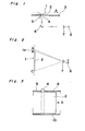
- Fig. 1 shows an optical system used for read-out in apparatuses such as a half-tone facsimile, a color copier, an optical character reader, and a color scanner wherein the optical signal of a character, a figure or an image can be read out automatically.
- a manuscript 2 placed between a back plate 1 and a carrier plate 3 is exposed with a light emitted from a fluorescent light 5 through a transparent window 4 of the carrier plate 3.
- Both back plate 1 and transparent window 4 extend over the manuscript 2 linearly in the direction perpendicular to the carriage direction A of a manuscript 2.
- the light having been reflected by the manuscript 2 is reflected by a mirror 6, passes through a focusing lens 7 and is detected with a photodetector, that is, a one-dimensional charge-coupled device (hereinafter refered to as CCD) 8.
- a photodetector that is, a one-dimensional charge-coupled device (hereinafter refered to as CCD) 8.
- Each element of the CCD 8 transmit an elecrtical singnal proportional to the intensity of the incident light to an output equipment such as a printer (not shown).
- a lighting control equipment comprises:
- the read-out of an image does not fluctuate even if the light intensity of the source of light changes in a time needed for the read-out of an image. This prevents the brightness of the output of an image to become irregular so that the performance of a read-out apparatus such as a facsimile can be improved largely.
- Fig. 2 shows an optical system for the read-out according to an embodiment of the present invention.
- a manuscript 2 is placed in front of a back plate 1, and the light from the manuscript 2 is projected through a lens 7 on a one-dimensional CCD 8.
- the optical system is so arranged that the light not only from mamuscript area (BC) but also from a monitor area la (AB) of the back plate 1 are projected on the CCD 8.
- the CCD 8 has 2048 elements, and the light from the white area AB is incident on from the first to the 128-th elements of the CCD 8 while that from the manuscript AB on the other elements.
- Fig. 3 shows a top plan view of the optical system.
- a manuscript 2 is placed between a left carrier guide 9 and a right one 10, and is carried along the direction of the arrow A.
- Both back plate 1 and transparent window 4 are extended over the left carrier guide 9, and the manuscript 2 is prevented by the carrier guides 9, 10 from passing the monitor area la, that is, the extended area of the back plate 1. Then, the brightness of the monitor area la can be monitored constantly through the transparent window 4 by the CCD 8.
- the fluorescent light 5 is lighted during an interval T FL per each scan period, and the lighting interval T FL is adjusted according to the detected brightness of the white monitor area la of the back plate 1.
- the light from the manuscript 2 and the white monitor area la is sensed by 2048 elements of the sensor part of the CCD 8 during T FL" and then the detected video signals are transfered to the memory part of the CCD 8 and are read out from the memory part successively.
- the lighting interval T FL of the fluorescent light 5 is adjusted according to the video signal V 1 of the white monitor area la detected lastly so as to keep the detected signal V 1 constant, as will be explained below.
- Fig. 4 shows a lighting control circuit which controls the lighting time T FL of the fluorescent light 5 according to the detected video signal of the monitor area la.
- the detected video signals are amplified successively by a CCD amplifier 11.
- the amplified signal V 1 is applied through an analog switch 12 to the + input terminal of a comparater 14.
- a capacitor 13 is connected between the + input terminal and the earth and averages the input signal V 1 .
- the analog switch 12 for the sample-hold is switched by a control circuit 15.
- the comparator 14 compares the input voltage V 2 at the + input terminal and the slice voltage V s applied to the - input terminal, and the output voltage V c is applied to an input terminal of a control circuit 15.
- the slice voltage Vs is a predetermined voltage to be compared with V 2 .
- the control circuit 15 gives a sample-hold signal T GATE to the analog switch 12. It also gives timing pulses T 0 and ⁇ T to the CCD 8 through a CCD driver 16 where T 0 is a fundamental pulse which can be used for the output of the video signal of each 2048 elements of the CCD 8 and ⁇ T is a pulse generated once per 4096 T 0 pulses at the start of each scan period.
- the control circuit 15 provides the interval T FL during which the fluorescent light 5 should be lighted to a lighting circuit 17 of the fluorescent light 5.
- Fig. 5 shows the circuit diagram of the control circuit 15.
- An oscillater 21 gives clock pulses T 0 to a 1/16 devider 22, a timing control circuit 23 and a timing pulse generator 24.
- the timing pulse generator 24 generates pulses ⁇ T and ⁇ ' T per 4096 T 0 pulses, and applies them to the CCD driver 16 and to the timing control circuit 23, respectively. After a pulse ⁇ T is generated the video signals of the 2048 elements of the CCD 8 are all read out, as will be explained later.
- the output T1 of the 1/16 devider 22 is connected to the count input CK of an up counter 25, while the output of the timing control circuit 23 is connected both to the analog switch 12 and through an inverter 26 to the count input CK of an up/down counter 27.
- the output T GATE makes the video signal V 1 pass through the analog switch 13, during a scan of the white monitor area la say between the 49-th and 80-th element of the CCD 8.
- the output of the comparator 14 is connected through an inverter 28 to the up/down count input terminal V/D of the up/down counter 27. According as the input voltage V 2 is larger or smaller than V s , the up/down counter 27 counts down or up at the negative edge of T GATE .
- the pulse ⁇ ' T is applied to the reset terminal R of the up counter 25, and to the set terminal S of a flip flop 29.
- the 8-bit output terminals A' 0 , A' 1 , ..., A' 7 of the up/down counter 27 and the 8-bit output terminals B' 0 , B' 1 , ..., B' 7 of the counter 25 are connected to the input terminals A 0 , A 1 ,...,A 7 and B 0' B 1' ...,B 7 of a digital comparator 30, respectively.
- the lighting time of the fluorescent light can be controlled by unit of ⁇ T in the circuit shown in Fig. 4.
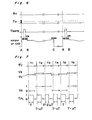
- Fig. 6 shows a timing chart of ⁇ T , T 0 T GATE and the output of CCD 8.
- the read-out of 2048 elements of CCD 8 is triggered by a pulse ⁇ T .
- the output of the video signal of each element is read out successively at each T 0 pulse.
- the first to 128-th elements are arranged corresponding to the white monitor area la, and the video signal from the 129-th to 2048-th elements correspondings to a manuscript 2.
- a sample-hold pulse T GATE becomes high and the analog switch 12 is switched on during a period corresponding to from the 49-th to the 80-th elements.
- the video signal V 1 is transmitted to the + input terminal of the comparator 14, and is holded as V 2 at the negative edge of T GATE'
- the CCD 8 is lighted with the fluorescent light 5 after a pulse ⁇ ' T during an adjusted time T FL which is made shorter or longer by ⁇ T according as the brightness (V 2 ) of the monitor area la is higher or lower than the predetermined reference brightness(V s ).
- the lighting time approaches to an appropriate value as follows.
- the output of the up/down counter 27 is 0 when electric power is turned on.
- the up counter 25 is reset with a pulse ⁇ ' T , and the flip flop 29 is set with the same ⁇ ' T , and its signal at the output terminal Q becomes 1.
- the fluorescent light 5 is turned on.
- the fluorescent light 5 lights only in a very short period.
- the video signals of the CCD 8 is read out. Because the lighting time is very short, V 2 is smaller than V , and V is 0.
- the up/down counter 27 is counted up by one at the negative edge of T GATE .
- the lighting time becomes AT in the following period. Similar processes are repeated till the brightness of the white monitor area la increases up to an appropriate value before a scan of a manuscript begins. After it attains to an appropriate value, the lighting time can be adjusted, for example, as shown in Fig. 7.
- Fig. 7 shows an example of the control of the lighting time of the fluorescent light 5.
- Each period t 1 , t 2 , ... begins with each ⁇ ' T pulse.
- the output V 4 of the comparator 14 becomes high or low according as V 2 is larger or smaller than the reference voltages V , and the lighting time is decreased or increased by ⁇ T from that of the last period according as the output V c of the comparator 14 is high or low.
- the white monitor area la is brighter than the reference brightness, that is, V2>V3, and the lighting time is allowed to decrease by AT from the value T of the last period t 1 .
- the white monitor area 1a is brighter again than the reference brightness, that is, V 2 >V 3 , and the lighting time is allowed to decrease again by AT from the value T- ⁇ T of the last period t 2 .
- the white monitor area la becomes brighter than the reference brightness, that is, V 2 ⁇ V 3 , and the lighting time is allowed to increase by AT from the value T-2AT of the last period t 3 . Similar processes are repeated.
- the fluctuation of the lighting intensity of the fluorescent light 5 integrated during a lighting time can be limited within a predetermined range by controlling the lighting time and the brightness of the white monitor area la detect by the CCD can be controlled within a predetermined fluctuation range.
- the integrated light intensity of the fluorescent light 5 incident on the manuscript can be kept constant, the video signal of the manuscript becomes uniform.
- the brightness of the white monitor area la of the back plate 1 is used to adjust the lighting time of the fluorescent light in order to get uniform output of the video signal of CCD.
- the brightness of the white monitor area la can be read-out at the end of each scan.
- three sources of light of three primary colors of red, green and blue can be controlled in an optical system of apparatuses such as a color scanner and a color copier.
Landscapes
- Engineering & Computer Science (AREA)
- Multimedia (AREA)
- Signal Processing (AREA)
- Facsimile Scanning Arrangements (AREA)
Applications Claiming Priority (2)
| Application Number | Priority Date | Filing Date | Title |
|---|---|---|---|
| JP17844/84 | 1984-02-01 | ||
| JP59017844A JPS60162377A (ja) | 1984-02-01 | 1984-02-01 | フアクシミリ,ocr等における調光装置 |
Publications (4)
| Publication Number | Publication Date |
|---|---|
| EP0150847A2 true EP0150847A2 (de) | 1985-08-07 |
| EP0150847A3 EP0150847A3 (en) | 1987-07-15 |
| EP0150847B1 EP0150847B1 (de) | 1990-10-24 |
| EP0150847B2 EP0150847B2 (de) | 1993-06-23 |
Family
ID=11954976
Family Applications (1)
| Application Number | Title | Priority Date | Filing Date |
|---|---|---|---|
| EP85100945A Expired - Lifetime EP0150847B2 (de) | 1984-02-01 | 1985-01-30 | Beleuchtungssteuerausstattung |
Country Status (4)
| Country | Link |
|---|---|
| US (1) | US4687919A (de) |
| EP (1) | EP0150847B2 (de) |
| JP (1) | JPS60162377A (de) |
| DE (1) | DE3580168D1 (de) |
Cited By (1)
| Publication number | Priority date | Publication date | Assignee | Title |
|---|---|---|---|---|
| EP0224956A1 (de) * | 1985-11-22 | 1987-06-10 | Agfa-Gevaert N.V. | Verfahren und Vorrichtung zum Abtasten und Digitalisieren von Bildern |
Families Citing this family (8)
| Publication number | Priority date | Publication date | Assignee | Title |
|---|---|---|---|---|
| US4876605A (en) * | 1987-01-12 | 1989-10-24 | Oki Electric Industry Co., Ltd. | Image reading device |
| US4831564A (en) * | 1987-10-22 | 1989-05-16 | Suga Test Instruments Co., Ltd. | Apparatus for estimating and displaying remainder of lifetime of xenon lamps |
| US4998043A (en) * | 1989-05-01 | 1991-03-05 | Fujikura Ltd. | LED stabilizing light source device |
| US4980759A (en) * | 1989-08-28 | 1990-12-25 | Polaroid Corporation | Calibration system and method for color image scanning |
| US5367223A (en) * | 1991-12-30 | 1994-11-22 | Hewlett-Packard Company | Fluoresent lamp current level controller |
| JPH0689000A (ja) * | 1992-09-08 | 1994-03-29 | Konica Corp | 複写機のミラー汚れ検出装置 |
| US6153888A (en) * | 1998-11-09 | 2000-11-28 | Fournier; John C. | Automatic control of reflective-type sensors in reproduction apparatus |
| DE19933199C1 (de) * | 1999-07-15 | 2001-01-25 | Daimler Chrysler Ag | Verfahren zur Erfassung von Helligkeitssignalen einer Mehrzahl lichtempfindlicher Sensorelemente |
Family Cites Families (5)
| Publication number | Priority date | Publication date | Assignee | Title |
|---|---|---|---|---|
| GB1452490A (en) * | 1973-12-21 | 1976-10-13 | Xerox Corp | Document copying apparatus |
| US4017180A (en) * | 1975-08-07 | 1977-04-12 | Adddressograph Multigraph Corporation | Exposure control for copying machine |
| JPS5913465A (ja) * | 1982-07-14 | 1984-01-24 | Canon Inc | 原稿読取装置 |
| JPS59223062A (ja) * | 1983-06-01 | 1984-12-14 | Canon Inc | 画像読取装置 |
| US4555621A (en) * | 1983-06-24 | 1985-11-26 | Xerox Corporation | Illumination control system utilizing an integrating feedback detector |
-
1984
- 1984-02-01 JP JP59017844A patent/JPS60162377A/ja active Pending
-
1985
- 1985-01-30 EP EP85100945A patent/EP0150847B2/de not_active Expired - Lifetime
- 1985-01-30 US US06/696,343 patent/US4687919A/en not_active Expired - Lifetime
- 1985-01-30 DE DE8585100945T patent/DE3580168D1/de not_active Expired - Lifetime
Cited By (1)
| Publication number | Priority date | Publication date | Assignee | Title |
|---|---|---|---|---|
| EP0224956A1 (de) * | 1985-11-22 | 1987-06-10 | Agfa-Gevaert N.V. | Verfahren und Vorrichtung zum Abtasten und Digitalisieren von Bildern |
Also Published As
| Publication number | Publication date |
|---|---|
| US4687919A (en) | 1987-08-18 |
| JPS60162377A (ja) | 1985-08-24 |
| EP0150847B2 (de) | 1993-06-23 |
| EP0150847B1 (de) | 1990-10-24 |
| DE3580168D1 (de) | 1990-11-29 |
| EP0150847A3 (en) | 1987-07-15 |
Similar Documents
| Publication | Publication Date | Title |
|---|---|---|
| EP0116435B1 (de) | Weissabgleich-Steuersystem | |
| US4688099A (en) | Illumination control circuitry for a film video player electronic strobe light | |
| EP0158962B1 (de) | CCD-Messwertgeberausgangsschaltung für Bildlesegerät | |
| US4618254A (en) | Automatic light control system | |
| US6386452B1 (en) | Image reading device with improved controller | |
| US5296944A (en) | Image scanner and dynamic range adjusting method thereof | |
| EP0165550B1 (de) | Farbbildlesevorrichtung | |
| EP0150847A2 (de) | Beleuchtungssteuerausstattung | |
| US4807239A (en) | Drive and control circuit for laser diode | |
| KR100479972B1 (ko) | 촬상장치및촬상방법 | |
| US4068943A (en) | Additive color printer control | |
| JPS63138887A (ja) | テレビジヨンカメラ用自動光量制御装置 | |
| US7274496B2 (en) | 4-line CCD sensor and image input apparatus using the same | |
| EP0742665B1 (de) | Verfahren und Vorrichtung zur Synchronisierung des Polarisierungsteuersignales einer wechselstrompolarisierten Lichtbogenentladungslampe mit der Beleuchtungszeitsignale eines CCD-Zeilensensors | |
| GB2172166A (en) | Bias lighting for telecine apparatus | |
| WO1986007515A1 (en) | Illumination control circuitry for a film video player electronic strobe light | |
| JPH10185684A (ja) | 固体走査型光書込み装置及びその光量測定方法 | |
| JPH03504305A (ja) | テレビ映画装置におけるドリフト修正 | |
| JP3524117B2 (ja) | 露光制御装置及びそれを用いた撮像装置 | |
| US4177449A (en) | Photoelectric converter apparatus | |
| JP2000224380A (ja) | 原稿読取装置 | |
| JPH02214259A (ja) | 画像読取装置 | |
| SU1429340A1 (ru) | Способ фотопечати и устройство дл его осуществлени | |
| JPS61198860A (ja) | イメ−ジ・スキヤナ駆動制御方式 | |
| JPH0119311B2 (de) |
Legal Events
| Date | Code | Title | Description |
|---|---|---|---|
| PUAI | Public reference made under article 153(3) epc to a published international application that has entered the european phase |
Free format text: ORIGINAL CODE: 0009012 |
|
| AK | Designated contracting states |
Designated state(s): DE FR GB |
|
| 17P | Request for examination filed |
Effective date: 19861224 |
|
| PUAL | Search report despatched |
Free format text: ORIGINAL CODE: 0009013 |
|
| AK | Designated contracting states |
Kind code of ref document: A3 Designated state(s): DE FR GB |
|
| RHK1 | Main classification (correction) |
Ipc: H04N 1/10 |
|
| 17Q | First examination report despatched |
Effective date: 19890630 |
|
| GRAA | (expected) grant |
Free format text: ORIGINAL CODE: 0009210 |
|
| AK | Designated contracting states |
Kind code of ref document: B1 Designated state(s): DE FR GB |
|
| ET | Fr: translation filed | ||
| REF | Corresponds to: |
Ref document number: 3580168 Country of ref document: DE Date of ref document: 19901129 |
|
| PLBI | Opposition filed |
Free format text: ORIGINAL CODE: 0009260 |
|
| 26 | Opposition filed |
Opponent name: CANON KABUSHIKI KAISHA Effective date: 19910724 |
|
| PUAH | Patent maintained in amended form |
Free format text: ORIGINAL CODE: 0009272 |
|
| STAA | Information on the status of an ep patent application or granted ep patent |
Free format text: STATUS: PATENT MAINTAINED AS AMENDED |
|
| 27A | Patent maintained in amended form |
Effective date: 19930623 |
|
| AK | Designated contracting states |
Kind code of ref document: B2 Designated state(s): DE FR GB |
|
| ET3 | Fr: translation filed ** decision concerning opposition | ||
| REG | Reference to a national code |
Ref country code: GB Ref legal event code: IF02 |
|
| PGFP | Annual fee paid to national office [announced via postgrant information from national office to epo] |
Ref country code: FR Payment date: 20040108 Year of fee payment: 20 |
|
| PGFP | Annual fee paid to national office [announced via postgrant information from national office to epo] |
Ref country code: GB Payment date: 20040128 Year of fee payment: 20 |
|
| PGFP | Annual fee paid to national office [announced via postgrant information from national office to epo] |
Ref country code: DE Payment date: 20040212 Year of fee payment: 20 |
|
| PG25 | Lapsed in a contracting state [announced via postgrant information from national office to epo] |
Ref country code: GB Free format text: LAPSE BECAUSE OF EXPIRATION OF PROTECTION Effective date: 20050129 |
|
| REG | Reference to a national code |
Ref country code: GB Ref legal event code: PE20 |