EP0150875A2 - Verfahren und Einrichtung zum Bestimmen des Anhaltezeitpunktes eines Flüssigkeitserneuerungsverfahrens - Google Patents
Verfahren und Einrichtung zum Bestimmen des Anhaltezeitpunktes eines Flüssigkeitserneuerungsverfahrens Download PDFInfo
- Publication number
- EP0150875A2 EP0150875A2 EP85200044A EP85200044A EP0150875A2 EP 0150875 A2 EP0150875 A2 EP 0150875A2 EP 85200044 A EP85200044 A EP 85200044A EP 85200044 A EP85200044 A EP 85200044A EP 0150875 A2 EP0150875 A2 EP 0150875A2
- Authority
- EP
- European Patent Office
- Prior art keywords
- light
- liquid
- renewed
- cells
- water
- Prior art date
- Legal status (The legal status is an assumption and is not a legal conclusion. Google has not performed a legal analysis and makes no representation as to the accuracy of the status listed.)
- Granted
Links
Images

Classifications
-
- G—PHYSICS
- G01—MEASURING; TESTING
- G01N—INVESTIGATING OR ANALYSING MATERIALS BY DETERMINING THEIR CHEMICAL OR PHYSICAL PROPERTIES
- G01N21/00—Investigating or analysing materials by the use of optical means, i.e. using sub-millimetre waves, infrared, visible or ultraviolet light
- G01N21/17—Systems in which incident light is modified in accordance with the properties of the material investigated
- G01N21/47—Scattering, i.e. diffuse reflection
- G01N21/49—Scattering, i.e. diffuse reflection within a body or fluid
- G01N21/53—Scattering, i.e. diffuse reflection within a body or fluid within a flowing fluid, e.g. smoke
-
- D—TEXTILES; PAPER
- D06—TREATMENT OF TEXTILES OR THE LIKE; LAUNDERING; FLEXIBLE MATERIALS NOT OTHERWISE PROVIDED FOR
- D06F—LAUNDERING, DRYING, IRONING, PRESSING OR FOLDING TEXTILE ARTICLES
- D06F34/00—Details of control systems for washing machines, washer-dryers or laundry dryers
- D06F34/14—Arrangements for detecting or measuring specific parameters
- D06F34/22—Condition of the washing liquid, e.g. turbidity
-
- D—TEXTILES; PAPER
- D06—TREATMENT OF TEXTILES OR THE LIKE; LAUNDERING; FLEXIBLE MATERIALS NOT OTHERWISE PROVIDED FOR
- D06F—LAUNDERING, DRYING, IRONING, PRESSING OR FOLDING TEXTILE ARTICLES
- D06F2103/00—Parameters monitored or detected for the control of domestic laundry washing machines, washer-dryers or laundry dryers
- D06F2103/20—Washing liquid condition, e.g. turbidity
-
- D—TEXTILES; PAPER
- D06—TREATMENT OF TEXTILES OR THE LIKE; LAUNDERING; FLEXIBLE MATERIALS NOT OTHERWISE PROVIDED FOR
- D06F—LAUNDERING, DRYING, IRONING, PRESSING OR FOLDING TEXTILE ARTICLES
- D06F2105/00—Systems or parameters controlled or affected by the control systems of washing machines, washer-dryers or laundry dryers
- D06F2105/06—Recirculation of washing liquids, e.g. by pumps or diverting valves
-
- D—TEXTILES; PAPER
- D06—TREATMENT OF TEXTILES OR THE LIKE; LAUNDERING; FLEXIBLE MATERIALS NOT OTHERWISE PROVIDED FOR
- D06F—LAUNDERING, DRYING, IRONING, PRESSING OR FOLDING TEXTILE ARTICLES
- D06F2105/00—Systems or parameters controlled or affected by the control systems of washing machines, washer-dryers or laundry dryers
- D06F2105/58—Indications or alarms to the control system or to the user
Definitions
- the invention relates to a method for the automatic determination, by comparison with a reference liquid, of the process of renewal of a renewed liquid of a device with renewed liquid, according to the clarity of this renewed liquid, using a light emitter providing light which, after passing through the reference liquid and the renewed liquid, is detected by light detectors, which, using electric means, make it possible to determine the clarity of the renewed liquid and to control its admission into the renewed liquid apparatus.
- a process according to the invention on which, by way of example, the invention is more particularly described, is illustrated by the cleaning operations, in particular those of rinsing linen, in a washing machine.
- any operation for cleaning other materials using other liquids according to said process is in accordance with the invention, as is the use of a reference liquid other than tap water.
- a common method of determining whether the flushing operation is sufficient, and can be stopped, is to observe the degree of clarity of the drain water.
- This method uses a light source emitting, separately in two opposite directions, light passing through two measurement cells each having their own light detector, the receiving cells, one of the rinsing water to be checked and the other l clean water from the city water supply pipe.
- the two detectors being similar, electrical means make it possible to compare the luminous flux of the cell containing the rinsing water with that of the cell containing the clean water.
- Optical measurements which can then be determined born from the measurement of the light flux passing through the cell containing the rinsing liquid, will gradually be more representative of the state of cleanliness of the walls of the cell than of the rinsing liquid itself; or else a delicate and expensive process to implement, consisting of cleaning the walls very frequently, is to be adapted to the washing machine.
- the object of the invention is to overcome as far as possible the increase in the state of dirtiness of the walls containing the liquid to be analyzed, and to avoid cleaning thereof.
- the light by first passing through the renewed liquid and the walls of the cell containing it, before passing through the cell containing the reference liquid, will undergo a reduction in light flux due to the state of dirtiness of the walls of the cell with renewed liquid, which is thus taken into account to define a state of clarity of the renewed liquid.
- the light flux reaching the reference liquid cell is no longer the light flux coming directly from the light source, but is reduced by its prior passage in the cell containing the renewed liquid.
- the light flux reaching the reference liquid cell will thus evolve with the state of cleanliness of the transparent walls of the cell containing the renewed liquid, so that this state of cleanliness will not disturb the final measurements made by the two detectors of light, these really translating the state of limpidity of the renewed liquid compared to the reference liquid.
- the light beam from the light source will pass through an equal number of walls capable of being opacified before reaching the light detectors.
- the two light detectors are connected to electrical means which make it possible to compare the light fluxes received by the two light detectors.
- a renewed water is sought having the characteristics closest to the reference water.
- the comparison will thus consist in having, received by the two cells, substantially equal luminous fluxes.
- the reference liquid consists of clean water and the renewed liquid consists of rinse water.
- the method applies to bringing a water called dirty into conformity with a reference water called clean during a water purification process.
- curves 98, 99 relating to the variations in resistance of a photoresistor as a function of the state of clarity of a liquid, respectively in the case of transmission (curve 98) and of diffusion (curve 99).
- the value of the resistance of the photoresistor varies in the opposite direction to the light flux received on this photoresistor.
- curve 98 is shown on a scale larger than that used for curve 99.
- the state of limpidity L O corresponds to very limpid water, that is to say to a maximum luminous flux received in transmission by a photoresistor, and very weak when it is detected in diffusion.
- the change in resistance of the photoresistor collecting the scattered light flux is much faster than the change in resistance collecting the transmitted light flux. The method of measuring the scattered light flux is therefore much more sensitive.
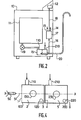
- FIG. 2 are represented only the essential elements making it possible to understand how the device for measuring the clarity of the water is inserted in a washing machine for the laundry 10.
- water is taken during use for the rinsing operation which the machine performs .
- This water enters the limpidity measuring device 15 as well as the reference water, in this case tap water, which it enters through the intake duct 210.
- the limpidity measuring device the water 15 delivers two electrical signals 16, which enter a comparison device 17, which delivers a comparison signal 18 when the signals are equal, which actuates the programmer 12, and signals 13, 14 alerting the user of a device defect.
- the cyclic operation of the washing machine 10 is therefore controlled by the comparison signal 18.
- FIG. 3 represents a detailed view of the device for measuring the clarity of the water 15. It consists of a light emitter 50 delivering an incident light beam 51, of a renewed liquid cell 100 having a conduit for inlet 110 and an outlet pipe 120 for the renewed liquid, in this case the rinsing water.
- a light flux detector 130 placed substantially perpendicular to the direction of propagation of the incident light beam 51 receives the light which is deflected by the particles contained in the renewed liquid.
- the limpidity measurement device 15 also comprises a reference liquid cell 200, in this case tap water, having an inlet duct 210 and an outlet duct 220.
- the light flux detectors 130, 230 deliver electrical signals 16 which are used by the comparison device 17 (FIG. 2).
- the faces 1, 2, 3, 4, 5 must have good transparency, over all or part of their extent, in order to allow the light coming from the incident light beam 51 to reach the renewed and reference liquids, then the detectors luminous flux 130, 230.
- the faces 1, 2, 3 are liable to be opacified in an equivalent manner.
- the measurements made with the light flux detectors 130, 230 respectively take into account the faces 1, 2 and the faces 1, 3.
- the opacity of the walls of the cell 100 will influence the two measurements in an equivalent manner.
- the faces 1, 3, 4 are arranged substantially perpendicular to the direction of the incident light beam 51 in order to transmit the maximum of light flux. Faces 2, 5 are substantially parallel to the direction of the incident light beam 51. However, an axis offset with respect to these positions remains in accordance with the invention. It is sufficient that the light flux arriving on the light flux detectors 130, 230 is sufficient to be exploited. Likewise non-planar faces 1, 2, 3, 4, 5 improving the directivity of the light beams is in accordance with the invention.
- the cells with renewed liquid 100 and of reference 200 can be formed by the separation by a plate of a larger cell.
- the outlet face 3 of the renewed liquid cell 100 and the inlet face 4 of the reference liquid cell 200 constitute the two faces of this plate.
- the measurement cells 100, 200 can consist of a single model, two copies of which are placed side by side. Between the faces 3 and 4 can therefore appear a space which is of no importance on the invention insofar as it does not disturb; not the propagation of light between the faces 3 and 4.
- the faces other than the faces 1, 2, 3, 4, 5 must not allow light to pass through, which means that if they are transparent to light which may disturb the measurements, all the cells must be sheathed or coated protection that does not allow a parasitic light phenomenon to disturb the measurements. Only the light from the light emitter 50 can be taken into account for the operation of the device.
- the device In the case of a washing machine, the device is designed to compensate over a very wide range for the slow and gradual darkening of the walls. In extreme cases where too much darkening appears, the cell containing the renewed liquid is replaced.
- the modular aspect of the device allows to replace only the cell containing the renewed liquid.
- the photoresistor In the absence of any light flux, the photoresistor will have a dark resistance R 0. When the walls let3 will darken during use of the device, less and less light will reach the liquid cell reference. It is necessary to maintain the luminous flux reaching it at a level higher than a threshold below which a replacement of the cell with renewed liquid is essential.
- This threshold can for example be fixed at a value R1 of the photoresistor. The latter varying in opposite direction to the light flux received must therefore remain below a value R I.
- City water can have a variable quality depending on the geographic location of the installation.
- City water can indeed be ferruginous or transport various substances: pipe debris, deposits ... which affect its clarity.
- the comparison device 17 will thus, at the start of each operation of the washing machine, test the operating state of the device for measuring the clarity of the water.
- the resistance values R 0 , R 1 , R 2 , R 230 , R 130 are translated in the comparison device 17 respectively into voltage levels U R0 , U R1 , U R2 , U R230 , V R130 which are compared with each other .
Landscapes
- General Health & Medical Sciences (AREA)
- Engineering & Computer Science (AREA)
- Life Sciences & Earth Sciences (AREA)
- Chemical & Material Sciences (AREA)
- Analytical Chemistry (AREA)
- Biochemistry (AREA)
- Health & Medical Sciences (AREA)
- Immunology (AREA)
- Physics & Mathematics (AREA)
- Pathology (AREA)
- General Physics & Mathematics (AREA)
- Textile Engineering (AREA)
- Investigating Or Analysing Materials By Optical Means (AREA)
- Accessory Of Washing/Drying Machine, Commercial Washing/Drying Machine, Other Washing/Drying Machine (AREA)
- Control Of Washing Machine And Dryer (AREA)
Applications Claiming Priority (2)
| Application Number | Priority Date | Filing Date | Title |
|---|---|---|---|
| FR8400980 | 1984-01-23 | ||
| FR8400980A FR2558610B1 (fr) | 1984-01-23 | 1984-01-23 | Procede et appareillage pour determiner l'instant d'arret d'un processus de renouvellement de liquide |
Publications (3)
| Publication Number | Publication Date |
|---|---|
| EP0150875A2 true EP0150875A2 (de) | 1985-08-07 |
| EP0150875A3 EP0150875A3 (en) | 1986-06-11 |
| EP0150875B1 EP0150875B1 (de) | 1989-05-10 |
Family
ID=9300376
Family Applications (1)
| Application Number | Title | Priority Date | Filing Date |
|---|---|---|---|
| EP85200044A Expired EP0150875B1 (de) | 1984-01-23 | 1985-01-18 | Verfahren und Einrichtung zum Bestimmen des Anhaltezeitpunktes eines Flüssigkeitserneuerungsverfahrens |
Country Status (5)
| Country | Link |
|---|---|
| US (1) | US4639137A (de) |
| EP (1) | EP0150875B1 (de) |
| JP (1) | JPS60162940A (de) |
| DE (1) | DE3570131D1 (de) |
| FR (1) | FR2558610B1 (de) |
Cited By (1)
| Publication number | Priority date | Publication date | Assignee | Title |
|---|---|---|---|---|
| EP0383218A1 (de) * | 1989-02-13 | 1990-08-22 | WAGNER, Georg | Verfahren zur Steuerung der Spülung einer programmgesteuerten Waschmaschine |
Families Citing this family (12)
| Publication number | Priority date | Publication date | Assignee | Title |
|---|---|---|---|---|
| US5011286A (en) * | 1989-08-03 | 1991-04-30 | Met One, Inc. | Multisensor particle counter utilizing a single energy source |
| US5084629A (en) * | 1990-05-07 | 1992-01-28 | Met One, Inc. | Split flow uniform multisensor detection |
| US5396178A (en) * | 1992-05-18 | 1995-03-07 | Dober Chemical Corporation | Apparatus and method for determining that equipment is clean |
| JP3074366B2 (ja) * | 1993-02-22 | 2000-08-07 | 東京エレクトロン株式会社 | 処理装置 |
| AU8026100A (en) * | 1999-10-15 | 2001-04-30 | The Administrators Of The Tulane Eductional Fund | Device for and method of simultaneously measuring light scatter from multiple liquid samples |
| US6307630B1 (en) * | 1999-11-19 | 2001-10-23 | Hach Company | Turbidimeter array system |
| GB0129668D0 (en) * | 2001-12-12 | 2002-01-30 | Procter & Gamble | Method for cleaning a soiled article |
| US6972424B1 (en) * | 2002-04-16 | 2005-12-06 | Pointsource Technologies, Llc | High detection rate particle identifier |
| DE10225842A1 (de) * | 2002-06-04 | 2003-12-24 | Zeiss Carl Smt Ag | Verfahren und Vorrichtung zur Bestimmung der Strahlungsbeständigkeit eines optischen Materials |
| US20060192940A1 (en) * | 2005-01-20 | 2006-08-31 | Phi-Wilson Janette T | Modular flow cytometry system |
| CN104695175B (zh) * | 2013-12-10 | 2017-12-01 | 苏州三星电子有限公司 | 一种具有浊度检测功能的洗衣机 |
| JP2016158744A (ja) * | 2015-02-27 | 2016-09-05 | パナソニックIpマネジメント株式会社 | 洗濯機 |
Family Cites Families (6)
| Publication number | Priority date | Publication date | Assignee | Title |
|---|---|---|---|---|
| US3200700A (en) * | 1959-04-23 | 1965-08-17 | Bowser Inc | Photoelectric comparison apparatus for indicating the amount of contamination in liquids |
| DE1485076A1 (de) * | 1963-06-14 | 1969-05-22 | Philips Patentverwaltung | Verfahren zum selbsttaetigen Ermitteln der zum Spuelen erforderlichen Wassermengen bei programmgesteuerten Wassermaschinen |
| GB1401426A (en) * | 1971-07-08 | 1975-07-16 | Wira & Mather | Method of and apparatus for determining when a rinsing or washing process should be terminated |
| US3870417A (en) * | 1973-07-17 | 1975-03-11 | Whirlpool Co | Sensor for dishwasher |
| AU523922B2 (en) * | 1978-04-28 | 1982-08-19 | Tokyo Shibaura Electric Company Ltd. | Apparatus for measuring the degree of rinsing |
| FR2485054A1 (fr) * | 1980-06-18 | 1981-12-24 | Labo Electronique Physique | Procede de detection du deteint au cours d'une operation de lavage dans une machine a laver et mise en oeuvre dudit procede |
-
1984
- 1984-01-23 FR FR8400980A patent/FR2558610B1/fr not_active Expired
-
1985
- 1985-01-15 US US06/691,597 patent/US4639137A/en not_active Expired - Fee Related
- 1985-01-18 DE DE8585200044T patent/DE3570131D1/de not_active Expired
- 1985-01-18 EP EP85200044A patent/EP0150875B1/de not_active Expired
- 1985-01-22 JP JP60008562A patent/JPS60162940A/ja active Granted
Cited By (1)
| Publication number | Priority date | Publication date | Assignee | Title |
|---|---|---|---|---|
| EP0383218A1 (de) * | 1989-02-13 | 1990-08-22 | WAGNER, Georg | Verfahren zur Steuerung der Spülung einer programmgesteuerten Waschmaschine |
Also Published As
| Publication number | Publication date |
|---|---|
| JPH0426420B2 (de) | 1992-05-07 |
| US4639137A (en) | 1987-01-27 |
| FR2558610B1 (fr) | 1986-05-09 |
| EP0150875B1 (de) | 1989-05-10 |
| EP0150875A3 (en) | 1986-06-11 |
| FR2558610A1 (fr) | 1985-07-26 |
| JPS60162940A (ja) | 1985-08-24 |
| DE3570131D1 (en) | 1989-06-15 |
Similar Documents
| Publication | Publication Date | Title |
|---|---|---|
| EP0150875B1 (de) | Verfahren und Einrichtung zum Bestimmen des Anhaltezeitpunktes eines Flüssigkeitserneuerungsverfahrens | |
| US4690560A (en) | Optically based measurement of fluid parameters | |
| EP1070953A1 (de) | Verfahren und Vorrichtung zur optischen Messung der Transparenz einer Flüssigkeit | |
| FR2514137A1 (fr) | Methode pour determiner le rayon moyen et/ou la longueur moyenne de particules entrainees par un milieu en ecoulement | |
| WO1995022755A1 (en) | Spectral detection of contaminants in containers | |
| FR2711426A1 (fr) | Procédé et dispositif pour caractériser, optimiser et contrôler automatiquement une méthode d'analyse par ressuage. | |
| FR2645961A1 (fr) | Dispositif de determination de caracteristiques de particules en suspension dans un liquide | |
| FR2712977A1 (fr) | Détecteur d'itensité lumineuse diffusée par des objets submicroniques en concentration élevée. | |
| EP3058336B1 (de) | Einheit zur messung der sedimentationsgeschwindigkeit von partikeln in suspension in einem fluid und vorrichtung mit mindestens einer derartigen einheit und einem automatischen probennehmer | |
| FR3134626A1 (fr) | Dispositif et méthode de numération de formule sanguine et de détermination de vitesse de sédimentation | |
| JP2008008794A (ja) | 分析装置 | |
| JP2018526644A (ja) | 液体培地中の物質濃度または物質を判断するための方法および装置 | |
| CN115236034B (zh) | 同时测量液体折射率和浊度的方法和系统以及装置 | |
| EP1526927A1 (de) | Automatische analyse- oder inspektionsvorrichtung für sich auf einer unterlage vorbeibewegende gegenstände | |
| EP0064110B1 (de) | Streuungsphotometer | |
| EP0731341A1 (de) | Vorrichtung zur Anzeige der Position der Separation zwischen zwei septischen Medien, und Detektionsverfahren damit | |
| FR2777354A1 (fr) | Procede et dispositif de mesure optique de la transparence d'un liquide | |
| FR2718528A1 (fr) | Appareil pour l'analyse en ligne de produits fluides polyphasés. | |
| FR2626075A1 (fr) | Procede et appareil pour determiner en continu par refractometrie la concentration d'une matiere soluble dans une solution liquide | |
| US20250327739A1 (en) | Water quality measurement device | |
| EP0682245B1 (de) | Verfahren zur Bestimmung der Zusammensetzung einer Flüssigkeit mit einem Spektralphotometer in mehreren Messbereichen | |
| FR2763685A1 (fr) | Appareil de mesure de l'evolution des caracteristiques optiques d'un milieu liquide ou gazeux en circulation | |
| EP0571269A1 (de) | Einrichtung zur Oberflächlichen-Messung des Gasgehaltes einer in einer durchsichtigen zylindrischen Röhre durchfliessenden Zwei-Phasenmischung | |
| SE2230143A1 (en) | Water quality measurement device | |
| JPWO2023218672A5 (de) |
Legal Events
| Date | Code | Title | Description |
|---|---|---|---|
| PUAI | Public reference made under article 153(3) epc to a published international application that has entered the european phase |
Free format text: ORIGINAL CODE: 0009012 |
|
| AK | Designated contracting states |
Designated state(s): DE FR GB IT |
|
| PUAL | Search report despatched |
Free format text: ORIGINAL CODE: 0009013 |
|
| AK | Designated contracting states |
Kind code of ref document: A3 Designated state(s): DE FR GB IT |
|
| 17P | Request for examination filed |
Effective date: 19861031 |
|
| 17Q | First examination report despatched |
Effective date: 19880705 |
|
| GRAA | (expected) grant |
Free format text: ORIGINAL CODE: 0009210 |
|
| AK | Designated contracting states |
Kind code of ref document: B1 Designated state(s): DE FR GB IT |
|
| REF | Corresponds to: |
Ref document number: 3570131 Country of ref document: DE Date of ref document: 19890615 |
|
| ITF | It: translation for a ep patent filed | ||
| GBT | Gb: translation of ep patent filed (gb section 77(6)(a)/1977) | ||
| PLBE | No opposition filed within time limit |
Free format text: ORIGINAL CODE: 0009261 |
|
| STAA | Information on the status of an ep patent application or granted ep patent |
Free format text: STATUS: NO OPPOSITION FILED WITHIN TIME LIMIT |
|
| REG | Reference to a national code |
Ref country code: FR Ref legal event code: CD |
|
| 26N | No opposition filed | ||
| PGFP | Annual fee paid to national office [announced via postgrant information from national office to epo] |
Ref country code: DE Payment date: 19920327 Year of fee payment: 8 |
|
| PGFP | Annual fee paid to national office [announced via postgrant information from national office to epo] |
Ref country code: GB Payment date: 19921223 Year of fee payment: 9 |
|
| PGFP | Annual fee paid to national office [announced via postgrant information from national office to epo] |
Ref country code: FR Payment date: 19930120 Year of fee payment: 9 |
|
| ITTA | It: last paid annual fee | ||
| PG25 | Lapsed in a contracting state [announced via postgrant information from national office to epo] |
Ref country code: DE Effective date: 19931001 |
|
| PG25 | Lapsed in a contracting state [announced via postgrant information from national office to epo] |
Ref country code: GB Effective date: 19940118 |
|
| GBPC | Gb: european patent ceased through non-payment of renewal fee |
Effective date: 19940118 |
|
| PG25 | Lapsed in a contracting state [announced via postgrant information from national office to epo] |
Ref country code: FR Effective date: 19940930 |
|
| REG | Reference to a national code |
Ref country code: FR Ref legal event code: ST |