EP0150911A2 - Batterie avec limitateur électronique de courant pour alimenter un récepteur - Google Patents
Batterie avec limitateur électronique de courant pour alimenter un récepteur Download PDFInfo
- Publication number
- EP0150911A2 EP0150911A2 EP85300085A EP85300085A EP0150911A2 EP 0150911 A2 EP0150911 A2 EP 0150911A2 EP 85300085 A EP85300085 A EP 85300085A EP 85300085 A EP85300085 A EP 85300085A EP 0150911 A2 EP0150911 A2 EP 0150911A2
- Authority
- EP
- European Patent Office
- Prior art keywords
- battery pack
- voltage
- comparator
- variable resistance
- resistance device
- Prior art date
- Legal status (The legal status is an assumption and is not a legal conclusion. Google has not performed a legal analysis and makes no representation as to the accuracy of the status listed.)
- Granted
Links
Images

Classifications
-
- H—ELECTRICITY
- H02—GENERATION; CONVERSION OR DISTRIBUTION OF ELECTRIC POWER
- H02H—EMERGENCY PROTECTIVE CIRCUIT ARRANGEMENTS
- H02H3/00—Emergency protective circuit arrangements for automatic disconnection directly responsive to an undesired change from normal electric working condition with or without subsequent reconnection ; integrated protection
- H02H3/08—Emergency protective circuit arrangements for automatic disconnection directly responsive to an undesired change from normal electric working condition with or without subsequent reconnection ; integrated protection responsive to excess current
- H02H3/087—Emergency protective circuit arrangements for automatic disconnection directly responsive to an undesired change from normal electric working condition with or without subsequent reconnection ; integrated protection responsive to excess current for DC applications
-
- H—ELECTRICITY
- H02—GENERATION; CONVERSION OR DISTRIBUTION OF ELECTRIC POWER
- H02H—EMERGENCY PROTECTIVE CIRCUIT ARRANGEMENTS
- H02H9/00—Emergency protective circuit arrangements for limiting excess current or voltage without disconnection
- H02H9/008—Intrinsically safe circuits
-
- H—ELECTRICITY
- H02—GENERATION; CONVERSION OR DISTRIBUTION OF ELECTRIC POWER
- H02H—EMERGENCY PROTECTIVE CIRCUIT ARRANGEMENTS
- H02H3/00—Emergency protective circuit arrangements for automatic disconnection directly responsive to an undesired change from normal electric working condition with or without subsequent reconnection ; integrated protection
- H02H3/02—Details
- H02H3/06—Details with automatic reconnection
-
- H—ELECTRICITY
- H02—GENERATION; CONVERSION OR DISTRIBUTION OF ELECTRIC POWER
- H02H—EMERGENCY PROTECTIVE CIRCUIT ARRANGEMENTS
- H02H7/00—Emergency protective circuit arrangements specially adapted for specific types of electric machines or apparatus or for sectionalised protection of cable or line systems, and effecting automatic switching in the event of an undesired change from normal working conditions
- H02H7/18—Emergency protective circuit arrangements specially adapted for specific types of electric machines or apparatus or for sectionalised protection of cable or line systems, and effecting automatic switching in the event of an undesired change from normal working conditions for batteries; for accumulators
-
- H—ELECTRICITY
- H02—GENERATION; CONVERSION OR DISTRIBUTION OF ELECTRIC POWER
- H02H—EMERGENCY PROTECTIVE CIRCUIT ARRANGEMENTS
- H02H9/00—Emergency protective circuit arrangements for limiting excess current or voltage without disconnection
- H02H9/001—Emergency protective circuit arrangements for limiting excess current or voltage without disconnection limiting speed of change of electric quantities, e.g. soft switching on or off
Definitions
- This invention relates to battery packs for powering electrical devices and more particularly to electronic circuitry used in association with battery packs to prevent overcurrent conditions in the output of the battery pack causing dangerous sparks.
- Portable battery packs are commonly used to power various forms of electrical devices which may be used in explosive types of environments, as found in mines, chemical treatment plants and flour mills to name only a few.
- portable battery packs are used to power lamps which are commonly affixed to the worker's helmet. Should the cable supplying power to the lamp be cut or abraded so as to short or cause an overcurrent condition, sparks can be generated which could set off an explosion in the environment.
- the electronic circuitry for a battery pack, overcomes this problem to provide a system which is classified as intrinsically safe for use in mines and other similar explosive environments.
- a battery pack for electrically powering an electrical device through an electrical cable has means for electronically determining an overcurrent condition in the cable or device and limiting current or switching off the voltage of the power pack.
- the electronic means comprises an electronic variable resistance device for controlling current through the cable.
- Means is provided for electronically sensing the current through the cable.
- the electronic variable resistance device reduces current in the cable to a predetermined maximum value in response to the sensing means sensing a current in excess of a predetermined maximum value.
- Means is provided for latching the electronic variable resistance device in the off condition after a predetermined time that the electronic variable resistance device has maintained current at or below the predetermined maximum value.
- Means is provided for resetting the latch means to permit the electronic variable resistance device to switch on and resume current through the cable.
- the electronic circuitry can be adapted to sense when the battery pack is being charged and turn off the lamp or the like which may be attached to the battery pack.
- the electronic circuitry can be adapted to provide a soft start up of a lamp bulb, when the battery pack is used with a lamp to prolong the lamp's useful life.
- the electronic circuitry can be adapted to prevent operation of the electrical device once the battery pack voltage has been reduced to a minimum level.
- a miner's lamp 10 is shown in Figure 1 which is powered by a portable battery pack 14 through the electrical cable 12.
- the miner's lamp 10 is mounted to the miner's helmet 18 by way of mounting device 16 in the standard manner.
- the portable battery pack 14 is conveniently carried about the miner's waist by means of a belt 20.
- the battery pack 14 consists of a cap portion 22 which is sealingly engaged with the body portion 30 at the seam 28.
- the cable 12 enters through the cap 22 of the battery case via connection 24 which grips the cable and prevents the cable from being removed from the cap.
- a waterproof connector 26 surrounds the cable 12 to prevent entrance of any water to within the battery pack 14.
- a manual switch 32 which is used to turn the lamp on and off and may optionally have cam arrangements to focus the lamp.
- the power pack 14 can be used to power devices other than electrical lamps.
- the portable power pack may be used to power maintenance equipment such as drills, saws and other hand implements used in various forms of underground maintenance, so that in general the power pack is adapted to power electrical devices which may or may not have a manual switch, such as switch 32 on the lamp 10 of Figure 1.
- the power pack is used in environments which can be explosive environments, such as in mines where explosive concentration of gases can develop or finely divided particulate matter as found in coal mines, it is important that the power pack be intrinsically safe, that is an overcurrent condition in the form of a short or failure in the unit will not cause sparks of a magnitude which can set off an explosion.
- an overcurrent condition in the device include a severing of the cable 12 causing at least a momentary excessive current flow or by abrasion, the wires of the cable become exposed which when they contact can cause a short.
- an intrinsically safe power pack is provided.
- the circuitry generally designated 34 controls the current through the lamp 10 via the cable 12.
- the manual switch 32 is provided externally of the circuitry 34.
- the battery pack 14 is connected across lines 36 and 38 where line 36 is positive and line 38 is negative.
- the battery pack 14 may consist of a series of batteries of the nickel-cadmium type which are rechargeable and have high power output for their relative size.
- terminals 40 and 42 are exterior of the base portion 30 of the battery pack and are on the inside thereof so they are not visible in Figure 1. Terminal 40 becomes positive and terminal 42 is negative when connected to a charging device.
- a diode 44 is inserted in line 46 connecting the positive charging terminal 40 to the positive side of power pack 14.
- the electronic circuit 34 is adapted to determine an overcurrent condition in the cable 12 or the electrical device such as lamp 10 and switch off the voltage of the power pack to the electrical device.
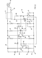
- An electronic variable resistance device 46 in the form of a field effect transistor (FET) is connected in series with manual switch 32 with its drain side on the switch 32 and its source side on the negative terminal of the power pack 14 and the gate is at the potential determined by resistor 48 on line 36.
- the parameters of the circuit are chosen such that the gate of the FET 46 is at sufficiently high potential to turn fully on the FET 46 to complete the circuit to the lamp 10 when the manual switch 32 is closed. In this state, the variable resistance device has minimal resistance.
- a voltage comparator 50 is used to determine when there is an overcurrent condition in the cable 12 or lamp 10 by sensing a sudden increase in current in line 52 due to a voltage drop across resistor 54.
- a second comparator 56 is used to latch the FET 46 in the off state when the short in the cable or lamp lasts for longer than a predetermined time period.
- Comparators 50 and 56 may be in the form of an integrated circuit having the pin markings 1 through 8.
- the voltage set for the comparator is determined at pin 5 by resistors 58 and 60 as they are connected across lines 36 and 38.
- resistors 58 and 60 As they are connected across lines 36 and 38.
- resistor 54 there is minimal voltage drop across resistor 54 due to low current flow as drawn by the lamp 10.
- the potential on pin 6, as determined at point 62 in combination with resistor 64 is below the potential of pin 5.
- the comparator 50 has a positive output at pin 7 so that it has no effect on the gate of the FET 46.
- the potential on pin 3 of comparator 56 is determined by resistors 64 and 66 as connected across lines 36 and 38, which is above the potential on pin 2 as determined by resistors 68 and 70.
- the output at pin 1 is also positive and maintains the potential determined by resistor 48 on the gate of the FET 46 to keep it fully on.
- the current in line 52 rapidly increases resulting in a significant voltage drop across resistor 54 which, by selecting the appropriate parameters in resistors 54 and 64, the pin voltage 6 rises above the pin voltage at 5. This causes an inversion in comparator 50 so that pin 7 output goes towards ground which lowers the voltage on the gate of FET 46.
- the variable resistance device 46 increases its resistance value to a level which limits the current flow through line 52 to a level at which the short cannot cause a spark which is capable of setting off an explosion.
- the parameters of the comparator and resistors is selected to react quickly to the occurrence of the overcurrent condition, preferably within one to five milliseconds of the short occurring. If the short is only momentary and is removed, the circuitry goes back to normal where current in line 52 reduces, resulting in the comparator 50 inverting to provide a positive output at pin 7.
- the circuit remains in this stabilized state for a predetermined time period which is determined by the latching device 56.
- the capacitor 72 commences charging by way of the current through resistor 68.
- the capacitor 72 elevates the potential on pin 2 eventually to a level (depending upon the time constant of resistor 68, capacitor 72) above the potential on pin 3.
- the comparator 56 then inverts to drop the output of pin 1 towards ground which removes the potential from gate of FET 46 to latch the FET 46 completely off.
- the variable resistance device 46 has essentially an infinite resistance to current in line 52.
- the comparator 56 does not invert again until the capacitor 72 can discharge.
- the capacitor 72 will not discharge as long as the short remains and the switch 32 is closed.
- the capacitor 72 discharges through resistor 70 and depending upon its time constant, determines when the potential on pin 2 falls below the potential of pin 3 to invert comparator 56 and allow its output at pin 1 to go positive applying the necessary voltage on the gate of FET 46 to fully open the FET 46.
- the comparators 50 and 56 there may be a tendency for the comparators to oscillate. This is eliminated by placement of a capacitor 55 across pins 1 and 4 of the two comparators.
Landscapes
- Charge And Discharge Circuits For Batteries Or The Like (AREA)
- Emergency Protection Circuit Devices (AREA)
- Protection Of Static Devices (AREA)
- Compositions Of Oxide Ceramics (AREA)
- Luminescent Compositions (AREA)
- Saccharide Compounds (AREA)
- Polysaccharides And Polysaccharide Derivatives (AREA)
- Compounds Of Unknown Constitution (AREA)
- Battery Mounting, Suspending (AREA)
- Preparation Of Compounds By Using Micro-Organisms (AREA)
- Diaphragms For Electromechanical Transducers (AREA)
- External Artificial Organs (AREA)
Priority Applications (1)
| Application Number | Priority Date | Filing Date | Title |
|---|---|---|---|
| AT85300085T ATE51475T1 (de) | 1984-01-17 | 1985-01-07 | Batterieanordnung mit elektronischer strombegrenzung zur versorgung eines elektrischen verbrauchers. |
Applications Claiming Priority (2)
| Application Number | Priority Date | Filing Date | Title |
|---|---|---|---|
| CA000445472A CA1212990A (fr) | 1984-01-17 | 1984-01-17 | Lampe electrique a surete integree pour mineurs |
| CA445472 | 1984-01-17 |
Publications (3)
| Publication Number | Publication Date |
|---|---|
| EP0150911A2 true EP0150911A2 (fr) | 1985-08-07 |
| EP0150911A3 EP0150911A3 (en) | 1985-08-28 |
| EP0150911B1 EP0150911B1 (fr) | 1990-03-28 |
Family
ID=4126964
Family Applications (1)
| Application Number | Title | Priority Date | Filing Date |
|---|---|---|---|
| EP85300085A Expired - Lifetime EP0150911B1 (fr) | 1984-01-17 | 1985-01-07 | Batterie avec limitateur électronique de courant pour alimenter un récepteur |
Country Status (9)
| Country | Link |
|---|---|
| US (1) | US4634936A (fr) |
| EP (1) | EP0150911B1 (fr) |
| AT (1) | ATE51475T1 (fr) |
| AU (1) | AU579128B2 (fr) |
| CA (1) | CA1212990A (fr) |
| DE (1) | DE3576890D1 (fr) |
| GB (1) | GB2156611B (fr) |
| IE (1) | IE55961B1 (fr) |
| ZA (1) | ZA85189B (fr) |
Cited By (1)
| Publication number | Priority date | Publication date | Assignee | Title |
|---|---|---|---|---|
| GB2323983A (en) * | 1997-04-01 | 1998-10-07 | Xerox Corp | Current inrush control |
Families Citing this family (28)
| Publication number | Priority date | Publication date | Assignee | Title |
|---|---|---|---|---|
| JPS61165997A (ja) * | 1984-12-10 | 1986-07-26 | 林原 健 | 白熱電球点燈装置 |
| US4749934A (en) * | 1986-11-07 | 1988-06-07 | Alexander Manufacturing Company | Intrinsically safe battery circuit |
| US5144207A (en) * | 1989-05-12 | 1992-09-01 | Brunson Robert L | Circuit and method for igniting and operating an arc lamp |
| US5072347A (en) * | 1989-05-12 | 1991-12-10 | Brunson Robert L | Search light |
| US5353205A (en) * | 1993-01-29 | 1994-10-04 | Hudak H John | Cockpit blackout search & survival light |
| JP3272108B2 (ja) * | 1993-07-07 | 2002-04-08 | 三洋電機株式会社 | パック電池 |
| JP3069498B2 (ja) * | 1994-09-01 | 2000-07-24 | 富士通株式会社 | 充放電装置および電子機器 |
| US5896010A (en) * | 1995-09-29 | 1999-04-20 | Ford Motor Company | System for controlling lighting in an illuminating indicating device |
| US5683831A (en) * | 1996-03-29 | 1997-11-04 | Itt Defense, Inc. | Compact battery pack for a helmet mounted night vision device |
| JP3571536B2 (ja) * | 1997-10-20 | 2004-09-29 | 富士通株式会社 | バッテリ充電装置及び方法並びに電子装置 |
| US6184654B1 (en) * | 1998-07-28 | 2001-02-06 | Double-Time Battery Corporation | Wearable docking-holster system, with energy management, to support portable electronic devices |
| US6469619B1 (en) | 1999-04-20 | 2002-10-22 | The United States Of America As Represented By The Department Of Health And Human Services | Intrinsically-safe roof hazard alert module |
| USD448099S1 (en) | 2000-06-21 | 2001-09-18 | Henry J. Mariani | Rechargeable hand lantern |
| US7473221B2 (en) * | 2000-10-19 | 2009-01-06 | Applied Medical Resources Corporation | Surgical access apparatus and method |
| US6768622B2 (en) * | 2000-11-30 | 2004-07-27 | Micrel, Incorporated | Method and apparatus for providing thermal shutdown and current limiting protection |
| US7682036B2 (en) * | 2001-04-11 | 2010-03-23 | General Manufacturing, Inc. | Intrinsically safe light |
| DE10146581C1 (de) * | 2001-09-21 | 2003-04-24 | Infineon Technologies Ag | Schaltungsanordnung mit einem Halbleiterschalter und einer Schutzschaltung |
| DE10201505B4 (de) * | 2002-01-17 | 2004-03-18 | Dbt Automation Gmbh | Arbeitsschutzvorrichtung für Bergleute |
| US6888267B2 (en) * | 2002-01-29 | 2005-05-03 | Rockwell Automation Technologies, Inc. | Battery backed memory with low battery voltage trip, disconnect and lockout |
| US6925419B2 (en) * | 2003-05-16 | 2005-08-02 | Fisher-Rosemount Systems, Inc. | Intrinsically safe field maintenance tool with removable battery pack |
| US20050017680A1 (en) * | 2003-07-10 | 2005-01-27 | Liguo Zhao | Power source |
| US7586292B1 (en) * | 2005-05-09 | 2009-09-08 | Electrochem Solutions, Inc. | Low voltage cutoff circuit for an electrochemical cell |
| US8690375B2 (en) * | 2008-01-11 | 2014-04-08 | Koehler-Bright Star, Inc. | Power cord mounted electronic module for portable lamp |
| US8450944B2 (en) * | 2008-02-05 | 2013-05-28 | J. Baxter Brinkman International Corporation | Intelligent light for controlling lighting level |
| US20090195179A1 (en) * | 2008-02-05 | 2009-08-06 | Joseph Peter D | Power line communication |
| KR101089849B1 (ko) * | 2009-12-16 | 2011-12-05 | 삼성전기주식회사 | 씨모스(cmos) 회로에 적합한 전압 레귤레이터 |
| US10879519B2 (en) | 2018-12-17 | 2020-12-29 | Bayco Products, Inc. | Spark protection apparatus for intrinsically safe, battery-operated devices |
| CN113713275B (zh) * | 2021-09-27 | 2023-05-09 | 四川省医学科学院·四川省人民医院 | 一种医用烤灯 |
Family Cites Families (17)
| Publication number | Priority date | Publication date | Assignee | Title |
|---|---|---|---|---|
| US3558982A (en) * | 1968-05-29 | 1971-01-26 | Gen Electric | Current limiting protective means |
| DE1763890A1 (de) * | 1968-08-31 | 1971-12-30 | Siemens Ag | UEberlastschutzschaltung |
| US3818273A (en) * | 1971-03-26 | 1974-06-18 | Yokogawa Electric Works Ltd | Barrier isolator device employing an overload protection circuit |
| US3691426A (en) * | 1971-10-26 | 1972-09-12 | Teledyne Inc | Current limiter responsive to current flow and temperature rise |
| FR2235514B1 (fr) * | 1973-06-28 | 1977-12-23 | Telecommunications Sa | |
| FR2250238B1 (fr) * | 1973-11-05 | 1976-05-07 | Snecma | |
| US4150302A (en) * | 1977-04-25 | 1979-04-17 | Roche Thomas F | Emergency light battery charger circuit |
| US4203141A (en) * | 1978-03-30 | 1980-05-13 | Wescom, Inc. | Low power dissipation series regulator for PCM repeater lines |
| GB2077525A (en) * | 1980-06-03 | 1981-12-16 | Jenkins James Oliver Michael | Battery recharger and rechargeable flash lamp |
| US4360851A (en) * | 1980-07-17 | 1982-11-23 | Portable Tool & Electronics Inc. | Electronic circuit breaker |
| FR2497424A1 (fr) * | 1980-12-31 | 1982-07-02 | Telemecanique Electrique | Appareil detecteur du type a deux bornes alimente en courant alternatif redresse sous une tension pouvant varier dans une large gamme avec commande de la charge a l'aide de thyristors de commutation |
| US4321648A (en) * | 1981-02-25 | 1982-03-23 | Rca Corporation | Over-current protection circuits for power transistors |
| DE3116846A1 (de) * | 1981-04-28 | 1982-12-09 | Siemens AG, 1000 Berlin und 8000 München | Anordnung zum schutz gegen ueberlastung eines als verstaerker arbeitenden leistungstransistors |
| DE3121754C1 (de) * | 1981-06-01 | 1982-12-09 | Siemens AG, 1000 Berlin und 8000 München | Leistungsschalter mit einem Feldeffekttransistor |
| US4438473A (en) * | 1981-07-21 | 1984-03-20 | The United States Of America As Represented By The Secretary Of The Interior | Power supply for an intrinsically safe circuit |
| DE3271158D1 (en) * | 1982-08-26 | 1986-06-19 | Stephanois Rech Mec | Safe electric supply glow discharge |
| US4513343A (en) * | 1982-12-27 | 1985-04-23 | Eaton Corporation | Short circuit protector having fold-back trip point for solid state switching device |
-
1984
- 1984-01-17 CA CA000445472A patent/CA1212990A/fr not_active Expired
- 1984-01-25 US US06/573,651 patent/US4634936A/en not_active Expired - Lifetime
-
1985
- 1985-01-07 EP EP85300085A patent/EP0150911B1/fr not_active Expired - Lifetime
- 1985-01-07 DE DE8585300085T patent/DE3576890D1/de not_active Expired - Lifetime
- 1985-01-07 IE IE32/85A patent/IE55961B1/xx unknown
- 1985-01-07 AT AT85300085T patent/ATE51475T1/de active
- 1985-01-08 ZA ZA85189A patent/ZA85189B/xx unknown
- 1985-01-08 GB GB08500441A patent/GB2156611B/en not_active Expired
- 1985-01-09 AU AU37545/85A patent/AU579128B2/en not_active Ceased
Cited By (1)
| Publication number | Priority date | Publication date | Assignee | Title |
|---|---|---|---|---|
| GB2323983A (en) * | 1997-04-01 | 1998-10-07 | Xerox Corp | Current inrush control |
Also Published As
| Publication number | Publication date |
|---|---|
| GB2156611B (en) | 1987-09-16 |
| AU579128B2 (en) | 1988-11-17 |
| EP0150911A3 (en) | 1985-08-28 |
| ZA85189B (en) | 1985-09-25 |
| GB8500441D0 (en) | 1985-02-13 |
| US4634936A (en) | 1987-01-06 |
| EP0150911B1 (fr) | 1990-03-28 |
| IE55961B1 (en) | 1991-02-27 |
| ATE51475T1 (de) | 1990-04-15 |
| GB2156611A (en) | 1985-10-09 |
| IE850032L (en) | 1985-07-17 |
| DE3576890D1 (de) | 1990-05-03 |
| CA1212990A (fr) | 1986-10-21 |
| AU3754585A (en) | 1985-07-25 |
Similar Documents
| Publication | Publication Date | Title |
|---|---|---|
| EP0150911A2 (fr) | Batterie avec limitateur électronique de courant pour alimenter un récepteur | |
| US4727306A (en) | Portable battery charger | |
| GB2135537A (en) | Emergency lighting apparatus | |
| ES2132291T3 (es) | Dispositivo electronico, paquete de bateria y cargador para el paquete de bateria. | |
| KR19980021547A (ko) | 배터리 보호 기능을 갖는 배터리 팩 | |
| MX2011011118A (es) | Adaptador cargador de bateria recargable y de linterna y su protector. | |
| ATE102763T1 (de) | Ueber-entladungsschutzschaltung. | |
| CA1320939C (fr) | Lampe de recherche | |
| US5334925A (en) | Nickel cadmium battery deep cycler device | |
| US4536695A (en) | Discharging protection device for battery-operated portable electric light | |
| KR100580381B1 (ko) | 2차전지의과충전방지회로 | |
| KR20050109765A (ko) | 배터리 보호회로 | |
| US5692825A (en) | Torches | |
| KR0137233Y1 (ko) | 전기 발파기 | |
| GB2312343A (en) | Mains powered alarm device with rechargeable battery backup | |
| GB2245437A (en) | Power supply for energising a portable telephone from a vehicle battery | |
| CA1130376A (fr) | Indicateur de decharge d'un accumulateur | |
| KR200330437Y1 (ko) | 방폭용 배터리 | |
| RU42131U1 (ru) | Устройство для определения полного заряда серебряно-цинковой аккумуляторной батареи | |
| KR920003542Y1 (ko) | 승강기 비상등 제어장치 | |
| KR880003309Y1 (ko) | 밧데리 충전제어회로 | |
| JPS5463334A (en) | Spare power source monitor | |
| KR20000015185U (ko) | 밧데리의 과전류 차단장치 | |
| SU1762332A1 (ru) | Устройство дл контрол состо ни предохранител | |
| KR970056722A (ko) | 자동 충전 차단 기능을 갖는 무선 전화기 |
Legal Events
| Date | Code | Title | Description |
|---|---|---|---|
| PUAI | Public reference made under article 153(3) epc to a published international application that has entered the european phase |
Free format text: ORIGINAL CODE: 0009012 |
|
| PUAL | Search report despatched |
Free format text: ORIGINAL CODE: 0009013 |
|
| AK | Designated contracting states |
Designated state(s): AT CH DE FR GB IT LI SE |
|
| AK | Designated contracting states |
Designated state(s): AT CH DE FR GB IT LI SE |
|
| 17P | Request for examination filed |
Effective date: 19860219 |
|
| 17Q | First examination report despatched |
Effective date: 19880203 |
|
| GRAA | (expected) grant |
Free format text: ORIGINAL CODE: 0009210 |
|
| AK | Designated contracting states |
Kind code of ref document: B1 Designated state(s): AT CH DE FR GB IT LI SE |
|
| PG25 | Lapsed in a contracting state [announced via postgrant information from national office to epo] |
Ref country code: SE Effective date: 19900328 Ref country code: LI Effective date: 19900328 Ref country code: IT Free format text: LAPSE BECAUSE OF FAILURE TO SUBMIT A TRANSLATION OF THE DESCRIPTION OR TO PAY THE FEE WITHIN THE PRESCRIBED TIME-LIMIT;WARNING: LAPSES OF ITALIAN PATENTS WITH EFFECTIVE DATE BEFORE 2007 MAY HAVE OCCURRED AT ANY TIME BEFORE 2007. THE CORRECT EFFECTIVE DATE MAY BE DIFFERENT FROM THE ONE RECORDED. Effective date: 19900328 Ref country code: CH Effective date: 19900328 Ref country code: AT Effective date: 19900328 |
|
| REF | Corresponds to: |
Ref document number: 51475 Country of ref document: AT Date of ref document: 19900415 Kind code of ref document: T |
|
| REF | Corresponds to: |
Ref document number: 3576890 Country of ref document: DE Date of ref document: 19900503 |
|
| ET | Fr: translation filed | ||
| REG | Reference to a national code |
Ref country code: CH Ref legal event code: PL |
|
| PLBE | No opposition filed within time limit |
Free format text: ORIGINAL CODE: 0009261 |
|
| STAA | Information on the status of an ep patent application or granted ep patent |
Free format text: STATUS: NO OPPOSITION FILED WITHIN TIME LIMIT |
|
| 26N | No opposition filed | ||
| REG | Reference to a national code |
Ref country code: GB Ref legal event code: IF02 |
|
| PGFP | Annual fee paid to national office [announced via postgrant information from national office to epo] |
Ref country code: GB Payment date: 20020109 Year of fee payment: 18 |
|
| PGFP | Annual fee paid to national office [announced via postgrant information from national office to epo] |
Ref country code: FR Payment date: 20020110 Year of fee payment: 18 |
|
| PGFP | Annual fee paid to national office [announced via postgrant information from national office to epo] |
Ref country code: DE Payment date: 20020212 Year of fee payment: 18 |
|
| PG25 | Lapsed in a contracting state [announced via postgrant information from national office to epo] |
Ref country code: GB Free format text: LAPSE BECAUSE OF NON-PAYMENT OF DUE FEES Effective date: 20030107 |
|
| PG25 | Lapsed in a contracting state [announced via postgrant information from national office to epo] |
Ref country code: DE Free format text: LAPSE BECAUSE OF NON-PAYMENT OF DUE FEES Effective date: 20030801 |
|
| GBPC | Gb: european patent ceased through non-payment of renewal fee |
Effective date: 20030107 |
|
| PG25 | Lapsed in a contracting state [announced via postgrant information from national office to epo] |
Ref country code: FR Free format text: LAPSE BECAUSE OF NON-PAYMENT OF DUE FEES Effective date: 20030930 |
|
| REG | Reference to a national code |
Ref country code: FR Ref legal event code: ST |