EP0150944B1 - Dispositif applicateur pour appliquer des cartons porteurs à des articles groupés - Google Patents
Dispositif applicateur pour appliquer des cartons porteurs à des articles groupés Download PDFInfo
- Publication number
- EP0150944B1 EP0150944B1 EP19850300222 EP85300222A EP0150944B1 EP 0150944 B1 EP0150944 B1 EP 0150944B1 EP 19850300222 EP19850300222 EP 19850300222 EP 85300222 A EP85300222 A EP 85300222A EP 0150944 B1 EP0150944 B1 EP 0150944B1
- Authority
- EP
- European Patent Office
- Prior art keywords
- carrier
- base plate
- locating
- walls
- wall
- Prior art date
- Legal status (The legal status is an assumption and is not a legal conclusion. Google has not performed a legal analysis and makes no representation as to the accuracy of the status listed.)
- Expired
Links
- 239000011087 paperboard Substances 0.000 claims description 5
- 210000003739 neck Anatomy 0.000 description 10
- 239000000969 carrier Substances 0.000 description 8
- 238000010276 construction Methods 0.000 description 3
- 238000005192 partition Methods 0.000 description 1
Images

Classifications
-
- B—PERFORMING OPERATIONS; TRANSPORTING
- B65—CONVEYING; PACKING; STORING; HANDLING THIN OR FILAMENTARY MATERIAL
- B65B—MACHINES, APPARATUS OR DEVICES FOR, OR METHODS OF, PACKAGING ARTICLES OR MATERIALS; UNPACKING
- B65B17/00—Other machines, apparatus, or methods for packaging articles or materials
- B65B17/02—Joining articles, e.g. cans, directly to each other for convenience of storage, transport, or handling
- B65B17/025—Joining articles, e.g. cans, directly to each other for convenience of storage, transport, or handling the articles being joined by a top carrier element
Definitions
- This invention relates to an applicator device for simultaneously applying a plurality of so- called top-gripping type of carriers onto a number of articles arranged in a group.
- the invention is particularly suitable for applying top gripping carriers to bottles which are accommodated in a crate so that several multi-bottle packages are formed whereafter individual packages may be grasped and removed from the crate.
- the applicator device which comprises a reciprocal head is, but need not be, adapted to receive known top gripping carriers.
- a known applicator for applying a top gripping type of paperboard carrier onto grouped bottles is disclosed in GB-A-1 427 510 in which arresting means are provided for engagement with a carrier within a locating zone of the applicator.
- the arresting means automatically engage and hold the carrier during application of the carrier on the bottles to be secured together and then automatically release the carrier.
- the present invention utilises natural resilience of the paperboard carrier, which tends to return the carrier to its non-erected condition, to hold the carrier against an arresting lip in the applicator from which it is released during loading by being displaced by the bottle necks introduced into the carrier.
- the invention provides an applicator device for applying at least one paperboard article carrier to a group of articles such as bottles which device comprises a base plate formed to provide a locating zone for each article carrier, each locating zone being adapted to receive an erected article carrier having apertured top and bottom walls interconnected by spaced side walls to form a generally tubular structure, said base plate having a plurality of spaced apertures formed in each of said locating zones for registry with like spaced apertures formed in the top and base walls of said carrier and arresting means carried by said base plate in each of said locating zones for engagement with the carrier adjacent one of the carrier side walls (known from GB-A-1427510), characterised in that a side wall of each locating zone of the applicator has a downwardly and outwardly inclined face which terminates remote from said base plate in an inwardly directed lip providing said arresting means so that the natural resilience of said carrier, which tends to return the carrier into its non-erected condition, cause the base wall of the carrier to be arrested by the arresting lip and the loading action
- the applicator head 10 comprises a base plate 12 from one surface 12a of which a series of spaced transverse walls depend.
- the series of walls include a first end wall 14 which has its outermost face flush with one end of the base plate 12; a first immediate wall 16 spaced from end wall 14; a second intermediate wall 18 spaced from intermediate wall 16; and a second end wall 20 spaced from intermediate wall 18 and which has its outermost face flush with the opposite end of the base plate.
- a longitudinal rib 22 extends centrally along surface 12a of the base plate and divides each of the transverse walls into two similar sections.
- the transverse walls and the longitudinal rib together define a number of carrier locating zones Z1-Z6. Thus, each locating zone is defined by a neighbouring pair of transverse walls and the longitudinal rib.
- the base plate is formed with four circular bottle-neck receiving apertures, e.g. apertures a,-a4 in zone Z 3 , the spacing of which is chosen so as to be in registry with aligned bottle-neck receiving apertures formed in the top and base walls of a suitably sized carton when positioned for loading in that locating zone.
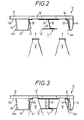
- the carton 'c' shown schematically in end view in locating zone Z, in FIGURE 2 comprises substantially parallel top and bottom walls 24, 26 respectively, interconnected by spaced side walls 28, 30 respectively, and central upstanding partition panel 32, thereby forming a generally tubular structure.
- Top wall 24 and bottom wall 26 are each formed with four bottle neck receiving apertures 'A' located in registry.
- the first transverse end wall 14 has a downwardly and outwardly inclined inner face 34 which terminates remote from surface 12a of base plate 12 in an inwardly directed arresting lip 34a.
- the inner face 34 also is formed with arcuate downwardly divergent recesses 36, 38 respectively, spaced for alignment with neighbouring bottle neck receiving apertures formed in the bottom panel of an adjacent bottle carrier.
- the arcuate recesses each provide clearance for receiving a portion of the periphery of a bottle neck when the bottle neck is inserted into an article carrier located in the locating zone.
- end wall 14 provides one transverse end of locating zones Z, and Z 4 the opposite end of which is provided by face 40 of the first intermediate wall 16.
- Face 40 also is formed with arcuate recesses 42 and 44, respectively, which are similar to recesses 36 and 38 but which are spaced for alignment with the opposite bottle neck receiving apertures of the same adjacent bottle carrier 'C'.
- the opposite face 46 of the first intermediate wall 16 is of similar construction and includes arcuate recesses 48 and 50. However, face 46 terminates remote from surface 12a of base plate 12 in an arresting lip 46a for locating zones Z 2 and Z s .
- the second intermediate wall 18 is of similar construction to intermediate wall 16 described above and therefore provides an arresting lip for locating zones Z 3 and 26.
- the second transverse end wall 20 also includes a downwardly and outwardly inclined inner face 52 but does not carry an arresting lip.
- Arcuate bottle neck clearance recesses 54, 56 are formed in the inner face 52 similar to those described in relation to end wall 14.
- the applicator head is mounted for vertical reciprocal movement in a carton applicator machine which is adapted to receive a loaded crate of bottles beneath applicator head when in its raised position.
- flat carriers are withdrawn from a hopper, erected and correctly loaded into the locating zones of the applicator head by suitable loading means.
- Each locating zone e.g. Zone Z, (see FIGURE 2) receives an erected carrier'c' such that the natural resilience of the paperboard carrier which tends to return the carrier into its flat (non-erected) condition causes the base wall 26 of the carrier (adjacent side wall 30) to be held arrested under the arresting lip 34a.
- Bottle carriers located in the other locating zones are similarly held in position and when the applicator head is fully loaded in which one bottle carrier is present in each locating zone, the applicator head is ready to execute an applicator stroke in relation to a crate of bottles therebelow. Thus, the applicator head is then moved downwards so that the bottle necks of bottles 'B' are received in the bottle neck receiving apertures of the carriers and the caps of the bottles pass into base plate apertures 'A'.
Landscapes
- Engineering & Computer Science (AREA)
- Mechanical Engineering (AREA)
- Container Filling Or Packaging Operations (AREA)
- Wrapping Of Specific Fragile Articles (AREA)
- Making Paper Articles (AREA)
Claims (6)
Applications Claiming Priority (2)
| Application Number | Priority Date | Filing Date | Title |
|---|---|---|---|
| GB8400748 | 1984-01-12 | ||
| GB848400748A GB8400748D0 (en) | 1984-01-12 | 1984-01-12 | Applicator device |
Publications (3)
| Publication Number | Publication Date |
|---|---|
| EP0150944A2 EP0150944A2 (fr) | 1985-08-07 |
| EP0150944A3 EP0150944A3 (en) | 1985-08-21 |
| EP0150944B1 true EP0150944B1 (fr) | 1988-04-20 |
Family
ID=10554865
Family Applications (1)
| Application Number | Title | Priority Date | Filing Date |
|---|---|---|---|
| EP19850300222 Expired EP0150944B1 (fr) | 1984-01-12 | 1985-01-11 | Dispositif applicateur pour appliquer des cartons porteurs à des articles groupés |
Country Status (4)
| Country | Link |
|---|---|
| EP (1) | EP0150944B1 (fr) |
| DE (1) | DE3562208D1 (fr) |
| ES (1) | ES8607162A1 (fr) |
| GB (1) | GB8400748D0 (fr) |
Cited By (1)
| Publication number | Priority date | Publication date | Assignee | Title |
|---|---|---|---|---|
| WO2025151771A1 (fr) * | 2024-01-11 | 2025-07-17 | Westrock Packaging Systems, Llc | Appareil de formation d'un support d'articles |
Families Citing this family (2)
| Publication number | Priority date | Publication date | Assignee | Title |
|---|---|---|---|---|
| SE507976C2 (sv) * | 1995-11-20 | 1998-08-03 | Rieber & Soen As | Sätt att bunta serier av flaskor samt anordning resp hållare för utförande av sättet |
| WO2020233943A1 (fr) | 2019-05-17 | 2020-11-26 | Krones Aktiengesellschaft | Dispositif d'emballage et procédé de fabrication d'unités d'emballage |
Family Cites Families (2)
| Publication number | Priority date | Publication date | Assignee | Title |
|---|---|---|---|---|
| US3492778A (en) * | 1967-09-30 | 1970-02-03 | Heinz Focke | Machine for mounting holding strips on elongated articles,preferably bottles |
| GB1427510A (en) * | 1972-06-09 | 1976-03-10 | Gauntlett J H | Applicator for container carriers |
-
1984
- 1984-01-12 GB GB848400748A patent/GB8400748D0/en active Pending
-
1985
- 1985-01-11 ES ES539504A patent/ES8607162A1/es not_active Expired
- 1985-01-11 DE DE8585300222T patent/DE3562208D1/de not_active Expired
- 1985-01-11 EP EP19850300222 patent/EP0150944B1/fr not_active Expired
Cited By (1)
| Publication number | Priority date | Publication date | Assignee | Title |
|---|---|---|---|---|
| WO2025151771A1 (fr) * | 2024-01-11 | 2025-07-17 | Westrock Packaging Systems, Llc | Appareil de formation d'un support d'articles |
Also Published As
| Publication number | Publication date |
|---|---|
| GB8400748D0 (en) | 1984-02-15 |
| ES539504A0 (es) | 1986-05-16 |
| DE3562208D1 (en) | 1988-05-26 |
| EP0150944A2 (fr) | 1985-08-07 |
| EP0150944A3 (en) | 1985-08-21 |
| ES8607162A1 (es) | 1986-05-16 |
Similar Documents
| Publication | Publication Date | Title |
|---|---|---|
| US12378023B2 (en) | Packaging system | |
| US5437143A (en) | Method of forming a package of beverage cans | |
| EP0017333B1 (fr) | Machine d'emballage | |
| EP0277030B1 (fr) | Emballage pour le groupement de récipients | |
| EP0456448A2 (fr) | Emballage multipack enveloppant avec poignée de transport | |
| EP1225134A2 (fr) | Porte-articles et flan pour l'obtenir | |
| US4389832A (en) | Method and apparatus for loading bottles into open top bottle carriers | |
| RU2114038C1 (ru) | Держатель для бутылок с захватом сверху, единая заготовка для его выполнения и способ упаковки | |
| US5476217A (en) | Carton bottle partition | |
| US3822012A (en) | Multiple container package arrangements | |
| EP0150944B1 (fr) | Dispositif applicateur pour appliquer des cartons porteurs à des articles groupés | |
| US3812958A (en) | Carton for plurality of containers | |
| US5485713A (en) | Method and apparatus for inserting partitions into article groups | |
| US4505089A (en) | Carrier applicator | |
| US3924385A (en) | Apparatus for enclosing container groups | |
| FI85127C (fi) | Mekanism samt foerfarande foer att paolaegga en medbringarkartong av toppgripande typ utanpao en grupp av produkter. | |
| US3339726A (en) | Carrier | |
| US3492774A (en) | Method and apparatus for packaging containers in a one-piece carrier | |
| KR100362816B1 (ko) | 판지상자내에물품층을포장하는포장기계와포장방법및그에따라형성된판지상자 | |
| CA1240958A (fr) | Combinaison de cartonnage-caisse enveloppant | |
| DE3173473D1 (en) | Device for applying a carrier tying several containers into one handling unit | |
| EP0447243B1 (fr) | Emballage multiple pour bouteilles consignables | |
| CA2082395C (fr) | Procede et installation de conditionnement | |
| AU683185C (en) | Carton bottle partition | |
| GB2077690A (en) | Method of applying gripper sleeves to groups of bottles |
Legal Events
| Date | Code | Title | Description |
|---|---|---|---|
| PUAI | Public reference made under article 153(3) epc to a published international application that has entered the european phase |
Free format text: ORIGINAL CODE: 0009012 |
|
| PUAL | Search report despatched |
Free format text: ORIGINAL CODE: 0009013 |
|
| AK | Designated contracting states |
Designated state(s): BE DE FR GB IT LU NL |
|
| AK | Designated contracting states |
Designated state(s): BE DE FR GB IT LU NL |
|
| 17P | Request for examination filed |
Effective date: 19860218 |
|
| 17Q | First examination report despatched |
Effective date: 19861015 |
|
| ITTA | It: last paid annual fee | ||
| GRAA | (expected) grant |
Free format text: ORIGINAL CODE: 0009210 |
|
| ITF | It: translation for a ep patent filed | ||
| AK | Designated contracting states |
Kind code of ref document: B1 Designated state(s): BE DE FR GB IT LU NL |
|
| REF | Corresponds to: |
Ref document number: 3562208 Country of ref document: DE Date of ref document: 19880526 |
|
| ET | Fr: translation filed | ||
| PG25 | Lapsed in a contracting state [announced via postgrant information from national office to epo] |
Ref country code: GB Effective date: 19890111 |
|
| PG25 | Lapsed in a contracting state [announced via postgrant information from national office to epo] |
Ref country code: LU Free format text: LAPSE BECAUSE OF NON-PAYMENT OF DUE FEES Effective date: 19890131 Ref country code: FR Effective date: 19890131 |
|
| PGFP | Annual fee paid to national office [announced via postgrant information from national office to epo] |
Ref country code: NL Payment date: 19890131 Year of fee payment: 7 Ref country code: BE Payment date: 19890131 Year of fee payment: 5 |
|
| PLBE | No opposition filed within time limit |
Free format text: ORIGINAL CODE: 0009261 |
|
| STAA | Information on the status of an ep patent application or granted ep patent |
Free format text: STATUS: NO OPPOSITION FILED WITHIN TIME LIMIT |
|
| 26N | No opposition filed | ||
| GBPC | Gb: european patent ceased through non-payment of renewal fee | ||
| PG25 | Lapsed in a contracting state [announced via postgrant information from national office to epo] |
Ref country code: DE Effective date: 19891003 |
|
| PG25 | Lapsed in a contracting state [announced via postgrant information from national office to epo] |
Ref country code: BE Effective date: 19900131 |
|
| BERE | Be: lapsed |
Owner name: THE MEAD CORP. Effective date: 19900131 |
|
| PG25 | Lapsed in a contracting state [announced via postgrant information from national office to epo] |
Ref country code: NL Effective date: 19900801 |
|
| NLV4 | Nl: lapsed or anulled due to non-payment of the annual fee | ||
| REG | Reference to a national code |
Ref country code: FR Ref legal event code: ST |