EP0151005A2 - Appareil pour déposer des échantillons liquides - Google Patents
Appareil pour déposer des échantillons liquides Download PDFInfo
- Publication number
- EP0151005A2 EP0151005A2 EP85300517A EP85300517A EP0151005A2 EP 0151005 A2 EP0151005 A2 EP 0151005A2 EP 85300517 A EP85300517 A EP 85300517A EP 85300517 A EP85300517 A EP 85300517A EP 0151005 A2 EP0151005 A2 EP 0151005A2
- Authority
- EP
- European Patent Office
- Prior art keywords
- micropipette
- liquid sample
- holder
- spotting
- elastic body
- Prior art date
- Legal status (The legal status is an assumption and is not a legal conclusion. Google has not performed a legal analysis and makes no representation as to the accuracy of the status listed.)
- Withdrawn
Links
Images

Classifications
-
- B—PERFORMING OPERATIONS; TRANSPORTING
- B01—PHYSICAL OR CHEMICAL PROCESSES OR APPARATUS IN GENERAL
- B01L—CHEMICAL OR PHYSICAL LABORATORY APPARATUS FOR GENERAL USE
- B01L3/00—Containers or dishes for laboratory use, e.g. laboratory glassware; Droppers
- B01L3/02—Burettes; Pipettes
- B01L3/0241—Drop counters; Drop formers
- B01L3/0262—Drop counters; Drop formers using touch-off at substrate or container
Definitions
- the present invention relates to a liquid sample-spotting apparatus, and more particularly pertains to a liquid sample-spotting apparatus for use in spotting a given trace amount of a liquid sample on a sheet-form chemical analytical element for clinical tests by means of a micropipette. Further, the invention relates to a process for spotting a liquid sample on an analytical element using said apparatus.
- test solutions Various body fluids are used as test solutions in clinical tests, and the most important test solution is blood. From the nature of the test solutions, it is important to use a small amount or a trace amount of a sample, and 5 ⁇ l,2 to 100 u;2 of the solution is generally subjected to analysis. It will be understood that in measuring a trace amount of a sample an error in the amount of a solution to be measured relatively increases with a reduction in the amount to be measured.
- the sheet-form chemical analytical element is particularly suitable for use in the analysis of a trace amount of a sample.
- a micropipette is usually used for measuring such trace amount of sample solution.
- Japanese Utility Model Provisional Publication No. 56(1981)-146241 discloses a liquid sample spotting apparatus which can keep the optimum operational conditions for spotting the liquid sample on the spreading layer of the sheet-form chemical analytical element with a manually operable micropipette and can reduce an operational error or an error due to an individual difference in order to minimize errors caused by the spotting conditions at the time of spotting the liquid sample. Since the liquid sample in this apparatus is caused to drop on the spreading layer of the sheet-form chemical analytical element, air bubbles may disadvantageously form within or on the surface of the liquid droplet supplied to said spreading layer so that the spreading conditions of the liquid sample within the spreading layer are adversely affected and fluctuations in the measured values increase.
- a body fluid sample such as serum or whole blood
- a body fluid sample such as serum or whole blood
- the spotting conditions must be always proper in order to obtain results with good reproducibility and high accuracy.
- a body fluid sample such as serum or whole blood
- a body fluid sample such as serum or whole blood
- spotting must be carried out under conditions such that the area to be spotted is nearly the center of the analytical slide and the liquid sample can be spread almost uniformly over the surface of the analytical element.
- the droplet of the liquid sample formed on the pointed end of the micropipette in such a manner that a portion of the droplet up to 1/3 or longer of the vertical length of the droplet measured from the lowest level of the droplet is contacted with the spreading layer of the sheet-form chemical analytical element before removing the micropipette.
- the whole amount of the liquid droplet is spotted gently to the spreading layer.
- the size as well as the length in the vertical direction of the droplet of the liquid sample formed on the pointed end of the micropipette varies depending on the type of the liquid sample, the shape and the diameter of the pointed end of the micropipette and the nature of the materials thereof.
- Spotting conditions for obtaining good analytical results are greatly influenced by the physical properties, particularly viscosity, of the liquid sample and the affinity of said liquid sample to the surface of the analytical element.
- a low-viscosity liquid such as urine
- a high-viscosity liquid such as blood, particularly whole blood
- Better results can be obtained only by gently contacting the sample with said element.
- it is difficult to constantly control the spotting conditions there is a limitation in relying on operator's experience and skill, and particularly errors are liable to be caused when spotting is made by different operators.
- It is an object of the present invention to provide a liquid sample spotting apparatus which can keep the optimum conditions for spotting a liquid sample without forming any air bubbles within the liquid droplet of said liquid sample in spotting said liquid sample on a sheet-form chemical analytical element with a manually operable micropipette, can minimize an operational error or an error due to an individual difference, enables the spotting of the liquid droplet of the liquid sample to be constantly carried out under the optimum conditions by a simple and rapid operation, can control the vertical position of the micropipette by a simple structure, hence can keep the micropipette at a proper position according to the type of the liquid sample, can smoothly conduct the elevating reset movement of the micropipette and can prevent the tip of the micropipette from being damaged.
- the present invention provides a liquid sample-spotting apparatus having a base, a holder which is mounted on said base by an elastic body in such a manner that said holder is movable downward in the vertical direction against an action of the elastic body for recovering the original form, and a manually operable micropipette which is detachably supported by said holder.
- the above-described apparatus can be employed in a process for spotting a liquid sample on an analytical element, which comprises steps of:
- liquid sample refers to aqueous solutions, particularly body fluids to be subjected to clinical tests, including blood, urine, saliva, spinal fluid, intestinal juice, pancreatic juice and the like as well as their diluted solutions prepared as analytical samples.
- potting refers to an operation comprising depositing (or supplying) dropwise an approximately predetermined amount of a liquid sample in the form of spot on the surface of a sheet-form chemical analytical element, or supplying an approximately predetermined amount of said liquid sample in the form of a spot to the surface of said chemical analytical element by gently bringing said liquid sample into contact with said element.
- micropipette refers to various kinds of pipettes capable of pipetting 100 41 or less of the sample.
- sheet-form chemical analytical element used herein refers to sheet-form dry analytical elements intended for the analysis of specific components (i.e., analyte) contained in body fluids in the field of clinical test, including those in the form of a strip, a film and a sheet.
- the analytical element is generally used in the form of a slide-form chemical analytical slide in which the element is put in a frame (slide frame) made of paper or a plastic material.
- multilayer chemical analytical elements which can be used in the present invention include integral analytical elements disclosed in, for example, Japanese Patent Provisional Publication Nos. 49(1974)-53888, 50(1975)-137192, 51(1976)-40191, 52(1977)-3488, 52(1977)-141786, 52(1977)-142584 and 55(1980)-33651, Japanese Patent Application Nos. 54(1979)-173624 and 55(1980)-435, etc.
- These multilayer chemical analytical elements have a sheet structure wherein one or more reagent layers and porous spreading layers are laminated onto a water-impermeable support to integrate them.
- a reaction for example, a color forming reaction proceeds in proportion to the amount of a substance to be analyzed.
- the content of said substance present in the liquid sample is detected and determined by conducting the photometry of color density after the lapse of a given time.
- Such a sheet-form chemical analytical element is characterized in that the outmost layer thereof comprises a porous membrane capable of uniformly spreading the liquid solution. The characteristics and the materials thereof are described in more detail in Japanese Patent Provisional Publication Nos. 49(1974)-53888, 55(1980)-90859, 55(1980)-164356, 57(1982)-148250, etc.
- a mechanism for automatically supplying a given amount of a liquid sample to such a multilayer chemical analytical element with an exclusive cup is disclosed in U.S. Patent No. 4,142,656 wherein the support of the multilayer chemical analytical element is raised toward a liquid sample supply port so as to bring the liquid droplet into contact with the surface layer of the multilayer chemical analytical element in carrying out the spotting of the liquid sample.
- Another embodiment for raising the support to bring the liquid droplet of the liquid sample into contact with the surface layer of the multilayer chemical analytical element is disclosed in U.S. Patent No. 4,041,995.
- a box 2 is mounted on a base 1, and the vertical plate 5 of a stationary plate 4 is screwed to the side plate 3 of the box 2 by screws 6.
- the fixed plate 4 is provided with a forked guide member 7 horizontally protruding at the upper part of the vertical plate 5.
- Through-holes 8 are vertically formed through the guide member 7.
- a holder 10 for a manually operable micropipette 9 is supported by the stationary plate 4 in such a manner the holder 10 can be moved in the vertical direction.
- the holder 10 is provided with notches 12 on both sides of the lower part of a vertical plate 11. There is provided protruding interlocking parts 13 on the front sides of the lower parts of these notches 12.
- Holding parts 14 are oppositely provided inside these interlocking parts 13.
- a pair of longitudinally extending positioning protrusions 15 are fixed by screws 16.
- a guide shaft 17 is fixed between each positioning protrusion 15 and each interlocking part 13.
- a supporting plate 18 is fixed by screws 19 and supporting parts 18a on both sides of the supporting plate 18 are protruded from the vertical plate 11 on both sides thereof.
- the vertical plate 11 there is provided a pair of holding pieces 20, and the intermediate part of the holding pieces 20 is rotatably supported by a vertical shaft 21, that is, the holding parts 20a are switchably (on-off operatably) supported, a compression spring 22 serving as an elastic body is provided between these holding pieces 20, and the holding parts 20a of the holding pieces 20 are energized in the direction of blockade by the spring of the compression spring 22.
- the holding parts 20a are expanded against the spring of the compression spring 22.
- the holder 10 is inserted so that when the notches 12 are interlocked with the guide parts 7, the guide shafts 17 are slidably inserted into the through-holes 8 formed within the guide part 7 of the stationary plate 4.
- a compression spring 23 serving as an elastic body and inserted into the guide shaft 17 is interposed between the positioning protrusion 15 and the guide part 7.
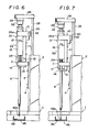
- the holder 10 is energized upward by the spring of these compression springs 23 and the ascending of the holder is regulated by the interlocking of the part 13 with the under surface of the guide part 7, while when the holder 10 is pushed downward, the holder 10 can be descended against the spring of the compression spring 23, and the descending thereof is regulated by the interlocking of the upper edge of the notch 12 with the upper surface of the guide part 7 (see, Fig. 7).
- a pair of operating shafts 25 (on the right and the left) extends through the upper plate 24 of the box 2 and is vertically movably supported, and a supporting plate 26 is horizontally provided at the upper protruding edge of the operating shaft 25.
- a pushing member 28 is inserted into the hole 27 of the supporting plate 26, and fixed to the supporting plate 26 by a screw 29.
- a motor (not shown) provided within the box is connected through a power transmission mechanism such as a cam (not shown) to the operating shafts 25.
- a switch 30 is on to drive the motor, there are intermittently moved up and down the operating shafts 25, the supporting plate 26 and the pushing member 28.
- a piston 32 supported by the main body 31 is made to descend against the spring of a compression spring (not shown) by depressing a knob 33, whereby the top of the manually operable micropipette 9 is inserted into a liquid sample.
- the knob 33 is then released, whereby the piston is reset upward by the spring of the compression spring and the micropipette sucks up the liquid sample.
- the micropipette When the micropipette is moved in parallel with axis, the upper enlarged part 34 of the main body 31 is inserted into the inner side of the guide parts 7 and the positioning protrusions 14 and the holding parts 20a of the holding pieces 20 are expanded against the spring of the compression spring 22, the micropipette can be elastically supported by the holding parts 20a and the lower narrow part 35 of the main body 31 can be forcedly inserted into the inner side of holding parts 14, thus holding the micropipette.
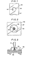
- a chemical analytical slide 36 comprises a thin plastic frame 37 and a sheet-form multilayer chemical analytical element 38, for example, as shown in Figs. 1 to 3.
- the frame 37 has a liquid sample dropping hole 39 at the central part of the upper surface thereof and a photometric hole 40 at the central part of the lower surface thereof.
- the multilayer chemical analytical element 38 comprises a water-impermeable transparent support 41, a reagent layer 43 (provided on said support 41) and a porous spreading layer 44 (provided on said reagent layer 43), said reagent layer 43 containing a reagent capable of producing optically detectable change (e.g.
- optical reflection density by a chemical reaction, for example, by a color reaction in proportion to the amount of an analyte contained in a liquid sample 42 and the spreading layer 44 being designed so as to supply approximately a given amount of the liquid sample per unit area to the reagent layer 43.
- the measuring element 38 is held in the frame 37 in such a manner that the porous spreading layer is turned upward.
- the knob 33 of the micropipette 9 is pushed to thereby descend the piston 32, whereby the micropipette is set at a height such that the liquid sample sucked up is discharged and a liquid droplet 42a is formed at the tip of the chemical analytical element 38 and at a position spaced away from the porous spreading layer 44 (see, Fig.
- micropipette is set such that when the micropipette 9 and the holder 10 are made to descend against the spring of the compression spring 23, a portion of the liquid droplet 42a, preferably a portion corresponding to 1/3 or longer of the length (measured from the lowest level of the droplet in the vertical direction) of the liquid droplet can be brought into contact with the spreading layer 44 of the chemical analytical element 38 to conduct gently spotting (see, Figs. 3 and 7).
- the following description relates to an operation for spotting the liquid sample 42a on the chemical analytical slide 36 by using the apparatus of the invention.
- a fresh chemical analytical element 36 is set in a regular state at a predetermined position within the sample supply passage 45 of the incubator as shown in Figs. 4 and 5.
- a liquid sample to be measured, for body fluid is then taken into the micropipette 9.
- the upper enlarged part 34 of the main body 31 of the micropipette 9 is forcedly press-fitted into the holding parts 20a of the holding pieces 20 to held it by the spring of the compression spring 22, and the lower narrow part 35 of the main body 31 is forcedly inserted into the inner side of the holding parts 14 to interlock the upper inclined part 35a thereof with the guide part 7, whereby the micropipette 9 is held so as not to descend against the holder 10.
- the micropipette 9 can be held by the upper position and the lower position so that it can be stabilized.
- the operating shafts 25, the supporting plate 26 and the pushing member 28 are descended by the power transmission mechanism by the driving of the motor.
- the pushing member 28 pushes the knob 33 of the micropipette 9 by this descending to thereby make the knob 33 and the piston 32 to descend by the spring of the compression spring, whereby the body fluid 42 taken into the micropipette is squeezed out to form the liquid droplet 42a at the tip of the micropipette.
- the micropipette 9 together with the holder is made to descend against the spring of the compression spring 23 as shown in figure 7 until the micropipette reaches the sample spotting position where at least 1/3 of the liquid droplet 42a formed on the tip thereof is brought into contact with the spreading layer 44 of the chemical analytical element 38 and the spotting of the liquid sample is effected (see, Figure 3).
- the spotting is carried out in such a manner that at least 1/3 of the length (in the direction of movement, i.e., in the direction of gravity drop) is brought into contact with the spreading layer 44 so that the exactly predetermined volume of the body fluid is uniformly developed in the form of a concentric circle on the spreading layer 44 to spot it as shown in Figure 2.
- the operating shafts 25, the supporting plate 26 and the pushing member 28 are made to ascend, whereby the micropipette 9 and the holder 10 are lifted by the spring of the compression spring 23 to reset them as shown in Fig. 6.
- the chemical analytical slide 36 after spotting is applied through a supply device (not shown) to the incubator, subjected to a photometric measurement and removed.
- the site to be spotted is variable or out of the center of the chemical analytical slide, the development is not uniform, unevenness in color formation is caused, or the photometric center does not coincide with the developed center so that the reproducibility of the measurement becomes poor and fluctuation in measured results are caused.
- the site to be spotted and the spotting conditions can be always controlled constant so that accuracy in the measurement using the integral multilayer chemical analytical element can be improved.
- any of the holding pieces 20 on both sides is rotatably supported so as to allow them to be opened and closed in the embodiment described above, they may be constructed such that one of the holding pieces 20 is fixed and the other is rotatably supported so as to allow it to be opened and closed.
- a tension spring is provided between a supporting part 18 and the rear end of the rotatable holding piece 20.
- the manually operable micropipette 9 there may be used one provided with a detachable plastic tip at the top thereof.
- the knob 33 of the micropipette 9 may be pushed by the hand or the lock of the locked pressing member is released to make the pushing member descend or rotate by the spring of an elastic body such as a spring whereby the knob is pushed, or other means may be used.
- the liquid droplet can be formed on the tip of the micropipette 9, said tip being spaced away from the chemical analytical slide, a relatively much space between the chemical analytical slide 36 and the tip of the micropipette 9 can be left so that when the chemical analytical slide is automatically supplied to a chemical analyzer or an incubator put therein and removed therefrom, the micropipette 9 can be prevented from being damaged by the abutting of the chemical analytical slide supply device or the chemical analytical slide against the tip of the micropipette, said chemical analytical slide supply device including any of an inclined type and a planar type.
- the apparatus of the invention may be combined with the chemical analyzer or the incubator put therein, or may be separately provided.
- a liquid droplet is formed on the pointed end of the micropipette and spaced away from the chemical analytical slide and the micropipette and the holder holding the micropipette are made to descend to bring the liquid drop into contact with the surface of the chemical analytical element so as to conduct gently spotting so that the spotting operation can be performed under the optimum conditions without forming any air bubbles in the liquid droplet at the time of spotting, an operational error or an error due to an individual difference can be minimized and the liquid droplet-spotting conditions can be always kept under the optimum conditions with a simple, rapid operation. Further, since the micropipette, etc.
- the descending position can be properly kept according to the kinds of the liquid sample by adjusting the pressing force against the micropipette, the ascending and resetting operations of the micropipette, etc. can be smoothly conducted and the pointed end of the micropipette can be prevented from being damaged.
Landscapes
- Health & Medical Sciences (AREA)
- Clinical Laboratory Science (AREA)
- Chemical & Material Sciences (AREA)
- Chemical Kinetics & Catalysis (AREA)
- Automatic Analysis And Handling Materials Therefor (AREA)
- Investigating Or Analysing Biological Materials (AREA)
- Sampling And Sample Adjustment (AREA)
Applications Claiming Priority (2)
| Application Number | Priority Date | Filing Date | Title |
|---|---|---|---|
| JP59011396A JPS60155942A (ja) | 1984-01-25 | 1984-01-25 | 液体試料点着装置 |
| JP11396/84 | 1984-01-25 |
Publications (2)
| Publication Number | Publication Date |
|---|---|
| EP0151005A2 true EP0151005A2 (fr) | 1985-08-07 |
| EP0151005A3 EP0151005A3 (fr) | 1987-09-02 |
Family
ID=11776848
Family Applications (1)
| Application Number | Title | Priority Date | Filing Date |
|---|---|---|---|
| EP85300517A Withdrawn EP0151005A3 (fr) | 1984-01-25 | 1985-01-25 | Appareil pour déposer des échantillons liquides |
Country Status (3)
| Country | Link |
|---|---|
| US (1) | US4737344A (fr) |
| EP (1) | EP0151005A3 (fr) |
| JP (1) | JPS60155942A (fr) |
Cited By (2)
| Publication number | Priority date | Publication date | Assignee | Title |
|---|---|---|---|---|
| US4873059A (en) * | 1985-12-20 | 1989-10-10 | Fuji Photo Film Co., Ltd. | Pipette device |
| US6689323B2 (en) | 1998-10-30 | 2004-02-10 | Agilent Technologies | Method and apparatus for liquid transfer |
Families Citing this family (45)
| Publication number | Priority date | Publication date | Assignee | Title |
|---|---|---|---|---|
| JPH076998B2 (ja) * | 1987-12-04 | 1995-01-30 | 富士写真フイルム株式会社 | 自動分注器および点着方法 |
| JPH0742113Y2 (ja) * | 1989-04-25 | 1995-09-27 | 石川島検査計測株式会社 | 重油燃料の試料採取装置 |
| US6416952B1 (en) | 1989-06-07 | 2002-07-09 | Affymetrix, Inc. | Photolithographic and other means for manufacturing arrays |
| US5744101A (en) | 1989-06-07 | 1998-04-28 | Affymax Technologies N.V. | Photolabile nucleoside protecting groups |
| US5800992A (en) | 1989-06-07 | 1998-09-01 | Fodor; Stephen P.A. | Method of detecting nucleic acids |
| US6955915B2 (en) * | 1989-06-07 | 2005-10-18 | Affymetrix, Inc. | Apparatus comprising polymers |
| US6551784B2 (en) | 1989-06-07 | 2003-04-22 | Affymetrix Inc | Method of comparing nucleic acid sequences |
| US5143854A (en) | 1989-06-07 | 1992-09-01 | Affymax Technologies N.V. | Large scale photolithographic solid phase synthesis of polypeptides and receptor binding screening thereof |
| US5925525A (en) * | 1989-06-07 | 1999-07-20 | Affymetrix, Inc. | Method of identifying nucleotide differences |
| US6919211B1 (en) * | 1989-06-07 | 2005-07-19 | Affymetrix, Inc. | Polypeptide arrays |
| US5250262A (en) | 1989-11-22 | 1993-10-05 | Vettest S.A. | Chemical analyzer |
| US5089229A (en) | 1989-11-22 | 1992-02-18 | Vettest S.A. | Chemical analyzer |
| EP0834575B1 (fr) * | 1990-12-06 | 2001-11-28 | Affymetrix, Inc. (a Delaware Corporation) | Identification d'acides nucléiques dans des échantillons |
| US5143849A (en) * | 1991-03-21 | 1992-09-01 | Eastman Kodak Company | Tip to surface spacing for optimum dispensing controlled by a detected pressure change in the tip |
| US5213764A (en) * | 1991-05-15 | 1993-05-25 | Miles Inc. | Metering device for slide analysis system |
| US6943034B1 (en) | 1991-11-22 | 2005-09-13 | Affymetrix, Inc. | Combinatorial strategies for polymer synthesis |
| CA2124087C (fr) * | 1991-11-22 | 2002-10-01 | James L. Winkler | Techniques combinees pour la synthese de polymeres |
| US6849462B1 (en) | 1991-11-22 | 2005-02-01 | Affymetrix, Inc. | Combinatorial strategies for polymer synthesis |
| US5344610A (en) * | 1993-02-03 | 1994-09-06 | Eastman Kodak Company | Aspirator probe with long pivot arm to minimize tip flick |
| US5273717A (en) * | 1992-09-30 | 1993-12-28 | Eastman Kodak Company | Self-calibrating analyzer aspirator |
| US5334353A (en) * | 1993-02-03 | 1994-08-02 | Blattner Frederick R | Micropipette device |
| US5525515A (en) * | 1993-02-03 | 1996-06-11 | Blattner; Frederick R. | Process of handling liquids in an automated liquid handling apparatus |
| US7625697B2 (en) | 1994-06-17 | 2009-12-01 | The Board Of Trustees Of The Leland Stanford Junior University | Methods for constructing subarrays and subarrays made thereby |
| US7323298B1 (en) | 1994-06-17 | 2008-01-29 | The Board Of Trustees Of The Leland Stanford Junior University | Microarray for determining the relative abundances of polynuceotide sequences |
| US6428752B1 (en) | 1998-05-14 | 2002-08-06 | Affymetrix, Inc. | Cleaning deposit devices that form microarrays and the like |
| US6722395B2 (en) | 1998-01-13 | 2004-04-20 | James W. Overbeck | Depositing fluid specimens on substrates, resulting ordered arrays, techniques for analysis of deposited arrays |
| US6269846B1 (en) | 1998-01-13 | 2001-08-07 | Genetic Microsystems, Inc. | Depositing fluid specimens on substrates, resulting ordered arrays, techniques for deposition of arrays |
| US6407858B1 (en) | 1998-05-14 | 2002-06-18 | Genetic Microsystems, Inc | Focusing of microscopes and reading of microarrays |
| US7095032B2 (en) * | 1998-03-20 | 2006-08-22 | Montagu Jean I | Focusing of microscopes and reading of microarrays |
| JP2003287534A (ja) * | 2002-03-28 | 2003-10-10 | Fuji Photo Film Co Ltd | 体液検査ユニットおよび体液検査装置 |
| ES2300509T3 (es) * | 2002-12-24 | 2008-06-16 | Humanitas Mirasole S.P.A. | Dispositivo analitico para cultivos celulares. |
| EP1911834A1 (fr) * | 2002-12-24 | 2008-04-16 | Istituto Clinico Humanitas | Dispositif analytique pour cultures cellulaires |
| US7273591B2 (en) * | 2003-08-12 | 2007-09-25 | Idexx Laboratories, Inc. | Slide cartridge and reagent test slides for use with a chemical analyzer, and chemical analyzer for same |
| US7396512B2 (en) | 2003-11-04 | 2008-07-08 | Drummond Scientific Company | Automatic precision non-contact open-loop fluid dispensing |
| US7588733B2 (en) * | 2003-12-04 | 2009-09-15 | Idexx Laboratories, Inc. | Retaining clip for reagent test slides |
| US7632468B2 (en) * | 2003-12-04 | 2009-12-15 | Idexx Laboratories, Inc. | Retaining clip for reagent test slides |
| US7955865B2 (en) * | 2004-06-09 | 2011-06-07 | The University Of British Columbia | Reagent delivery apparatus and methods |
| US20060281169A1 (en) * | 2005-06-14 | 2006-12-14 | Humanitas Mirasole S.P.A. | Analytical device for cell cultures |
| WO2008140742A1 (fr) * | 2007-05-08 | 2008-11-20 | Idexx Laboratories, Inc. | Analyseur chimique |
| US9103782B2 (en) | 2008-12-02 | 2015-08-11 | Malvern Instruments Incorporated | Automatic isothermal titration microcalorimeter apparatus and method of use |
| EP2409676A1 (fr) * | 2010-07-06 | 2012-01-25 | Intervet International B.V. | Procédé de dosage d'une formulation liquide contenant une substance médicale |
| US9797916B2 (en) | 2014-01-10 | 2017-10-24 | Idexx Laboratories, Inc. | Chemical analyzer |
| WO2021097612A1 (fr) * | 2019-11-18 | 2021-05-27 | 深圳迈瑞生物医疗电子股份有限公司 | Poussoir, mécanisme et procédé de chargement d'échantillon et support de stockage lisible par ordinateur |
| CN115836207B (zh) | 2020-07-10 | 2026-04-24 | Idexx实验室公司 | 护理点医学诊断分析仪、以及用于对样品进行医学诊断分析的装置、系统和方法 |
| US12517083B2 (en) * | 2023-03-19 | 2026-01-06 | Purdue Research Foundation | System and method for measuring electrochemistry of dynamically dissolving droplets |
Family Cites Families (6)
| Publication number | Priority date | Publication date | Assignee | Title |
|---|---|---|---|---|
| GB1209182A (en) * | 1967-03-15 | 1970-10-21 | Pye Ltd | Injectors for injecting measured micro-quantities of liquid samples |
| US3915651A (en) * | 1972-09-22 | 1975-10-28 | Us Government | Direct digital control pipette |
| US4041995A (en) * | 1975-01-30 | 1977-08-16 | Eastman Kodak Company | Gas pressure-activated drop dispenser |
| DE2554350A1 (de) * | 1975-12-03 | 1977-06-08 | Behringwerke Ag | Vorrichtung zum einfuellen von proben |
| DE2800771A1 (de) * | 1978-01-09 | 1979-07-19 | Hettich Andreas | Vorrichtung zur gleichzeitigen abgabe bzw. entnahme dosierter fluessigkeitsmengen, und arbeitsverfahren zum mischen bzw. verduennen von fluessigkeiten in beliebigem verhaeltnis |
| EP0042337B1 (fr) * | 1980-06-16 | 1986-03-12 | EASTMAN KODAK COMPANY (a New Jersey corporation) | Procédé et dispositif de distribution de doses de fluides biologiques |
-
1984
- 1984-01-25 JP JP59011396A patent/JPS60155942A/ja active Pending
-
1985
- 1985-01-25 EP EP85300517A patent/EP0151005A3/fr not_active Withdrawn
-
1987
- 1987-04-22 US US07/042,596 patent/US4737344A/en not_active Expired - Lifetime
Cited By (3)
| Publication number | Priority date | Publication date | Assignee | Title |
|---|---|---|---|---|
| US4873059A (en) * | 1985-12-20 | 1989-10-10 | Fuji Photo Film Co., Ltd. | Pipette device |
| US6689323B2 (en) | 1998-10-30 | 2004-02-10 | Agilent Technologies | Method and apparatus for liquid transfer |
| DE19950809B4 (de) * | 1998-10-30 | 2007-11-15 | Agilent Technologies, Inc. (n.d.Ges.d. Staates Delaware), Santa Clara | Verfahren und Vorrichtung für eine Flüssigkeitsübertragung |
Also Published As
| Publication number | Publication date |
|---|---|
| EP0151005A3 (fr) | 1987-09-02 |
| JPS60155942A (ja) | 1985-08-16 |
| US4737344A (en) | 1988-04-12 |
Similar Documents
| Publication | Publication Date | Title |
|---|---|---|
| US4737344A (en) | Liquid sample-spotting apparatus | |
| EP0163826B1 (fr) | Appareil pour éliminer du liquide de la surface externe d'un tube de pipette | |
| EP0246632A2 (fr) | Dispositif de pipettage muni d'un mécanisme automatique de remplacement des embouts | |
| US5508200A (en) | Method and apparatus for conducting multiple chemical assays | |
| US4452899A (en) | Method for metering biological fluids | |
| US4593728A (en) | Dispensing device and recording apparatus | |
| CA1333850C (fr) | Methode et dispositif pour diluer et melanger des specimens liquides | |
| EP1921439B1 (fr) | Dispositif, instrument et procede de mesure | |
| EP0042337B1 (fr) | Procédé et dispositif de distribution de doses de fluides biologiques | |
| US4356722A (en) | Apparatus for testing a liquid sample | |
| US6544796B1 (en) | System for producing multiple diagnostic test elements | |
| JP5148205B2 (ja) | 試料流体の表面張力を均一化する方法 | |
| EP0635710A2 (fr) | Dispositif et méthode pour le transfert de liquides sur une surface | |
| EP0120715A2 (fr) | Cellules de mesure optique | |
| US4539182A (en) | Automated reagent blotter | |
| CN116819071B (zh) | 一种免疫检测装置及方法 | |
| JPH10300709A (ja) | 液体成分の電気化学的検出又は測定装置、及びその方法 | |
| EP0339622B1 (fr) | Procédé et dispositif permettant de rendre hydrophobe un élément tubulaire | |
| JP3750772B2 (ja) | 生化学分析装置 | |
| US5320734A (en) | Test apparatus for measuring concentration of test substance in liquid | |
| JP5219221B2 (ja) | 試薬チップ押圧機構を備えた体液分析装置 | |
| JP2774052B2 (ja) | 液体試料自動分析装置 | |
| JPS62165147A (ja) | イオン活量測定用アナライザ− | |
| JP3853741B2 (ja) | インキュベータ | |
| US20040151621A1 (en) | Incubator |
Legal Events
| Date | Code | Title | Description |
|---|---|---|---|
| PUAI | Public reference made under article 153(3) epc to a published international application that has entered the european phase |
Free format text: ORIGINAL CODE: 0009012 |
|
| AK | Designated contracting states |
Designated state(s): DE FR GB |
|
| PUAL | Search report despatched |
Free format text: ORIGINAL CODE: 0009013 |
|
| AK | Designated contracting states |
Kind code of ref document: A3 Designated state(s): DE FR GB |
|
| 17P | Request for examination filed |
Effective date: 19871029 |
|
| 17Q | First examination report despatched |
Effective date: 19880527 |
|
| STAA | Information on the status of an ep patent application or granted ep patent |
Free format text: STATUS: THE APPLICATION IS DEEMED TO BE WITHDRAWN |
|
| 18D | Application deemed to be withdrawn |
Effective date: 19890613 |
|
| RIN1 | Information on inventor provided before grant (corrected) |
Inventor name: KOIZUMI, TERUAKI Inventor name: KITAJIMA, MASAO Inventor name: IGARASHI, TAKESHI |