EP0151011A2 - Elément résistant de sécurité - Google Patents
Elément résistant de sécurité Download PDFInfo
- Publication number
- EP0151011A2 EP0151011A2 EP85300542A EP85300542A EP0151011A2 EP 0151011 A2 EP0151011 A2 EP 0151011A2 EP 85300542 A EP85300542 A EP 85300542A EP 85300542 A EP85300542 A EP 85300542A EP 0151011 A2 EP0151011 A2 EP 0151011A2
- Authority
- EP
- European Patent Office
- Prior art keywords
- elements
- pins
- balls
- hard
- structure according
- Prior art date
- Legal status (The legal status is an assumption and is not a legal conclusion. Google has not performed a legal analysis and makes no representation as to the accuracy of the status listed.)
- Granted
Links
Images


Classifications
-
- F—MECHANICAL ENGINEERING; LIGHTING; HEATING; WEAPONS; BLASTING
- F41—WEAPONS
- F41H—ARMOUR; ARMOURED TURRETS; ARMOURED OR ARMED VEHICLES; MEANS OF ATTACK OR DEFENCE, e.g. CAMOUFLAGE, IN GENERAL
- F41H5/00—Armour; Armour plates
- F41H5/02—Plate construction
- F41H5/04—Plate construction composed of more than one layer
- F41H5/0414—Layered armour containing ceramic material
- F41H5/0421—Ceramic layers in combination with metal layers
-
- E—FIXED CONSTRUCTIONS
- E05—LOCKS; KEYS; WINDOW OR DOOR FITTINGS; SAFES
- E05G—SAFES OR STRONG-ROOMS FOR VALUABLES; BANK PROTECTION DEVICES; SAFETY TRANSACTION PARTITIONS
- E05G1/00—Safes or strong-rooms for valuables
- E05G1/02—Details
- E05G1/024—Wall or panel structure
-
- F—MECHANICAL ENGINEERING; LIGHTING; HEATING; WEAPONS; BLASTING
- F41—WEAPONS
- F41H—ARMOUR; ARMOURED TURRETS; ARMOURED OR ARMED VEHICLES; MEANS OF ATTACK OR DEFENCE, e.g. CAMOUFLAGE, IN GENERAL
- F41H5/00—Armour; Armour plates
- F41H5/02—Plate construction
- F41H5/023—Armour plate, or auxiliary armour plate mounted at a distance of the main armour plate, having cavities at its outer impact surface, or holes, for deflecting the projectile
Definitions
- the present invention relates to a penetration-resistant barrier structure for use in the doors or walls of safes, strongrooms and the like security enclosures and seeks in particular to provide a form of construction which can be made highly resistant to attacks with drills and punches and which will be suited especially to the localised protection of the locking points or other strategically important regions within a safe or strongroom door for example.
- barrier structures including elements of a hard mineral or ceramic disposed in a cast matrix.
- the hard elements are provided in the form of irregularly-shaped nuggets which must therefore be juxtaposed in a somewhat random fashion within the barrier, making it difficult to be sure that there is a sufficient depth of hard material evenly distributed throughout the barrier to provide adequate resistance over the whole of the protected area.
- One known variation of this comprises a closely-spaced parallel array of discrete high alumina ceramic pins held in a cast aluminium alloy matrix with the longitudinal axes of the pins being arranged perpendicularly to the plane of the barrier (ie parallel to the anticipated direction of attack upon the structure), generally in accordance with the teaching in United Kingdom patent specification No 1600247. While this kind of geometrical layout of the hard elements is useful in providing a consistent degree of resistance over the protected area while minimising the volume of the expensive hard material required to protect that area, it has been found that the resistance of the known barrier structure to drilling attacks and, especially, its resistance to attacks with percussion drills, punches or the like percussive tools, is less than that which is to be desired in high security applications. This is thought to be due both to the brittle nature of the ceramic pins employed in the known structure and to the fact that a cast matrix cannot provide sufficient support for the pins to prevent failure of the pins under impact loads.
- the present invention proposes a security barrier structure comprising a closely-spaced array of regularly-shaped hard elements of a cemented carbide material embedded in a supporting plate or other body, constructed by forcing the hard elements into respective members of an array of parallel bores prepared in the supporting body as an interference fit with the respective hard elements such that those elements are securely held under compression in the body by elastic stresses set up in the body as a result of the process of forcing in the hard elements, the longitudinal axes of said bores being aligned generally perpendicularly to the plane of the barrier.
- the hard elements in a structure according to the invention are preferably in the form of pins or balls of the chosen cemented carbide material.
- These materials also known as “sintered carbides” and “hard metals”, typically comprise compounds of tungsten carbide, titanium carbide or of both together and/or together with tantalum carbide, together with a small amount of a “cementing” metal such as cobalt or nickel.
- these materials can be made with both a sufficient hardness, say at least 1400 VPN (Vickers Pyramid Number) at room temperature, to resist the cutting action of the drills or other mechanical cutting tools which are likely to be appropriated for an attack upon the structure, and with a toughness and tensile strength (or transverse rupture strength - say at least 100,000 lb/in2 (7,000 kg/cm2) which significantly exceeds that of alumina and the like ceramic materials and which confers upon elements of cemented carbide a greater inherent resistance to destruction by percussion than the ceramics. Furthermore, and most importantly, these materials can also exhibit compressive strengths of, say, at least 400,000 lb/in2 (28,000 kg/cm2) and .
- the invention proposes to construct the structure by forcing the hard elements into interference-fit bores prepared in a supporting plate or other body.
- the residual elastic stresses which are set up in the body as a result of this force fitting of the hard elements exhibit a tightness of hold on the elements such as to maximise resistance to extraction of the elements and to minimise the tendency of the elements to crack or chip under impact loads.
- the hard elements are left with a significant induced compressive stress after the force-fitting step - since carbides are weaker in tension than in compression the net result of the induced compression is to increase the effective minimum stress at which failure occurs.
- Using a steel supporting body gives the further advantage of enabling the barrier to be strongly attached to the associated structure without difficulty eg by welding or other conventional fixation techniques.
- the form of the hard elements themselves can also be chosen so as to maximise the desired residual and induced stresses in the body and elements after force-fitting.
- the pins In the case of hard pins, therefore, which will be pressed or driven endwise into the body, it is preferred for the pins to be tapered along much or all of their length.
- balls may be employed, which have certain advantages from the point of view of production - they will be self-locating in the bores if poured over the surface of the supporting body and may be forced in by a rolling press.
- each pin 1 is tapered along its length, with a shallow dome at its wider end.
- the pins are mounted in the plate 2 with their longitudinal axes parallel to each other and the plate will be mounted in the safe door or other structure which it is intended to protect face-on to the anticipated direction of attack and with the domed ends of the pins outwards.
- the plate 2 is drilled with an array of plain bores 3 ( Figure 3) to define the positions for the pins 1, and with a diameter to be an interference fit with the pins.
- the narrower end of a pin 1 is then inserted into each bore 3 and the pins are pressed fully home as shown in Figure 2 whence they are securely retained,_under a considerable compressive load, by the very high elastic stresses which are induced in the steel surrounding each bore as the tapered pins progressively penetrate the plate.
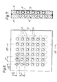
- an 8mm thick plate 2 of 50mm diameter is provided with an array of 7/64" (2.8mm) bores in the pattern shown in Figure 1 and at a pitch p of 6mm.
- the pins 1 are 8mm long and have a nominal diameter of 2.8mm widening to 3.4mm.
- This form of structure is particularly suitable for resisting carbide-tipped drills in the diameter range of 10-15mm; tests have shown that, when attacked, not only is progress through the barrier extremely slow due to the very low cutting rate which can be achieved in any event against the pins 1, but also the carbide drill tips are repeatedly destroyed so that the drill in use must be continually replaced if any progress at all is to be made.
- the structure illustrated in Figures 4 and 5 comprises a closely-spaced array of discrete tungsten carbide balls 4 held in a mild steel plate 5.
- the balls are mounted in the plate so as to lie generally in one plane and the plate will be mounted in the safe door or other structure which it is intended to protect face-on to the anticipated direction of attack and with the exposed faces of the balls outwards.
- this barrier is drilled with an array of plain blind bores 6 ( Figure 5) to define the positions for the balls 4, and with a diameter to be an interference fit with the balls.
- a ball 4 is then located in the mouth of each bore 6 and the balls are pressed fully home as shown in Figure 5 whence they are securely retained under compressive load by the very high elastic stresses which are induced in the steel surrounding each bore as the balls progressively penetrate the plate.
- this process tends to maximise resistance to extraction of the forced-in carbide elements and to minimise the tendency of these elements to crack or chip under impact loads, the resultant induced compressive stress in the hard inclusions also having the net result of increasing the effective minimum (tensile) stress at which failure of the carbide material occurs.
- a 6mm thick plate 2, 64mm square is provided with an array of 4.5mm deep 4.2mm diameter bores in the pattern shown in Figure 4 and at a pitch p' of 8mm.
- the balls 4 have a nominal diameter of 4.37mm.
- This form of structure is particularly suitable for resisting carbide-tipped drills in the diameter range of 10-20mm; tests have shown that, when attacked, not only is progress through the barrier extremely slow due to the very low cutting rate which can be achieved in any event against the hard balls 4, and that the spherical surfaces of the balls tend to deflect the drill, but also the carbide drill tips are repeatedly destroyed so that the drill in use must be continually replaced if any progress at all is to be made. ⁇ s before, this is due to the fact that the geometry of the barrier allows partial penetration of the drill tip into the steel plate whereupon the flanks of the carbide inserts on the drill bit impact the hard balls and are consequently broken or ripped away from the bit.
- FIGs 6 and 7 there is shown a construction which offers still greater protection against drilling and percussion attacks.
Landscapes
- Engineering & Computer Science (AREA)
- Chemical & Material Sciences (AREA)
- Ceramic Engineering (AREA)
- General Engineering & Computer Science (AREA)
- Earth Drilling (AREA)
- Drilling Tools (AREA)
Applications Claiming Priority (4)
| Application Number | Priority Date | Filing Date | Title |
|---|---|---|---|
| GB8402012 | 1984-01-26 | ||
| GB848402012A GB8402012D0 (en) | 1984-01-26 | 1984-01-26 | Security barrier structure |
| GB848406315A GB8406315D0 (en) | 1984-03-10 | 1984-03-10 | Security barrier structure |
| GB8406315 | 1984-03-10 |
Publications (3)
| Publication Number | Publication Date |
|---|---|
| EP0151011A2 true EP0151011A2 (fr) | 1985-08-07 |
| EP0151011A3 EP0151011A3 (en) | 1986-04-09 |
| EP0151011B1 EP0151011B1 (fr) | 1989-08-16 |
Family
ID=26287229
Family Applications (1)
| Application Number | Title | Priority Date | Filing Date |
|---|---|---|---|
| EP19850300542 Expired EP0151011B1 (fr) | 1984-01-26 | 1985-01-25 | Elément résistant de sécurité |
Country Status (6)
| Country | Link |
|---|---|
| EP (1) | EP0151011B1 (fr) |
| AU (1) | AU571639B2 (fr) |
| ES (1) | ES292802Y (fr) |
| GB (1) | GB2153406B (fr) |
| NZ (1) | NZ210987A (fr) |
| PT (1) | PT79886B (fr) |
Cited By (2)
| Publication number | Priority date | Publication date | Assignee | Title |
|---|---|---|---|---|
| EP1128154A3 (fr) * | 2000-02-21 | 2001-11-14 | Rafael Armament Development Authority Ltd. | Plaque de blindage ballistique |
| WO2018161072A1 (fr) * | 2017-03-03 | 2018-09-07 | The American University In Cairo | Plaques d'arrêt de projectile pour protection de personne, de véhicule et d'équipement |
Families Citing this family (1)
| Publication number | Priority date | Publication date | Assignee | Title |
|---|---|---|---|---|
| CN111705993B (zh) * | 2020-06-24 | 2024-01-05 | 王子国 | 预应力约束块和复合装甲结构 |
Family Cites Families (5)
| Publication number | Priority date | Publication date | Assignee | Title |
|---|---|---|---|---|
| BE711388A (fr) * | 1967-03-01 | 1968-08-28 | ||
| DE2525738A1 (de) * | 1975-06-10 | 1976-12-23 | Danzer Josef Helmut | Bohrsicheres plattenelement |
| GB1600247A (en) * | 1978-05-11 | 1981-10-14 | Security Lock & Safe Co | Security barriers |
| DE2933026A1 (de) * | 1979-08-16 | 1981-02-26 | Battelle Institut E V | Bauelement |
| FR2526535A1 (fr) * | 1982-05-04 | 1983-11-10 | Pequignot Michel | Plaque de blindage, notamment pour blindage allege |
-
1985
- 1985-01-25 PT PT7988685A patent/PT79886B/pt unknown
- 1985-01-25 AU AU38096/85A patent/AU571639B2/en not_active Ceased
- 1985-01-25 ES ES1985292802U patent/ES292802Y/es not_active Expired
- 1985-01-25 GB GB08501862A patent/GB2153406B/en not_active Expired
- 1985-01-25 EP EP19850300542 patent/EP0151011B1/fr not_active Expired
- 1985-01-29 NZ NZ21098785A patent/NZ210987A/en unknown
Cited By (3)
| Publication number | Priority date | Publication date | Assignee | Title |
|---|---|---|---|---|
| EP1128154A3 (fr) * | 2000-02-21 | 2001-11-14 | Rafael Armament Development Authority Ltd. | Plaque de blindage ballistique |
| US6892623B2 (en) | 2000-02-21 | 2005-05-17 | The State Of Israel, Ministry Of Defense, Armament Development Authority | Ballistic armor panel |
| WO2018161072A1 (fr) * | 2017-03-03 | 2018-09-07 | The American University In Cairo | Plaques d'arrêt de projectile pour protection de personne, de véhicule et d'équipement |
Also Published As
| Publication number | Publication date |
|---|---|
| GB8501862D0 (en) | 1985-02-27 |
| EP0151011B1 (fr) | 1989-08-16 |
| EP0151011A3 (en) | 1986-04-09 |
| PT79886B (en) | 1986-09-11 |
| AU571639B2 (en) | 1988-04-21 |
| NZ210987A (en) | 1987-11-27 |
| ES292802Y (es) | 1987-08-01 |
| GB2153406A (en) | 1985-08-21 |
| GB2153406B (en) | 1987-04-15 |
| PT79886A (en) | 1985-02-01 |
| ES292802U (es) | 1986-12-16 |
| AU3809685A (en) | 1985-08-01 |
Similar Documents
| Publication | Publication Date | Title |
|---|---|---|
| DE19950320A1 (de) | Verbundmaterial für die Panzerung | |
| DE3137855C2 (fr) | ||
| DE202008018132U1 (de) | Gebäudeabschluss in einbruchhemmender Ausführung | |
| US7000550B1 (en) | Ablative blast resistant security door panel | |
| EP1695019B1 (fr) | Structure protectrice et systeme protecteur | |
| EP0151011A2 (fr) | Elément résistant de sécurité | |
| US20160201356A1 (en) | Tamper resistant padlocks | |
| EP1705453B1 (fr) | Plaque de blindage composite pour protéger véhicules et bâtiments contre projectiles avec energie cinétique élevée | |
| DE4031550C2 (fr) | ||
| EP3431690B1 (fr) | Coffre-fort anti-effraction à construction multicouche | |
| DE3540820C2 (fr) | ||
| CA1172516A (fr) | Structure de renforcement pour murs et portes de chambres fortes et methode de fabrication | |
| DE102005001355B4 (de) | Riegelwerk für Wertbehältnisse | |
| AT380006B (de) | Mehrschichtiger intrusionsschutzkoerper | |
| DE2820642A1 (de) | Bohrgeraet | |
| DE2656795B2 (de) | Schlagwerkzeug zum Einsetzen in einen Abbau- bzw. Aufbruchhammer | |
| EP0150665B1 (fr) | Paroi de sécurité en béton | |
| DE10313231B4 (de) | Hochfeste Flächengebilde für endballistischen Schutz und Verschleißschutz | |
| CH668801A5 (en) | Composite armouring for strong room walls - has layer of elastic composite material within layers of beam-shaped members, contg. steel rope strands as reinforcement | |
| EP3270093B1 (fr) | Blindage et son procédé de fabrication | |
| US576742A (en) | Armor-plate | |
| US7287405B2 (en) | Drill resistant lock | |
| CH667690A5 (de) | Schlossschutzbeschlag. | |
| DE10336169B4 (de) | Komposit-Werkzeug für schlagende und/oder abrasive Belastungen | |
| DE3342734C2 (fr) |
Legal Events
| Date | Code | Title | Description |
|---|---|---|---|
| PUAI | Public reference made under article 153(3) epc to a published international application that has entered the european phase |
Free format text: ORIGINAL CODE: 0009012 |
|
| AK | Designated contracting states |
Designated state(s): BE FR IT LU NL |
|
| PUAL | Search report despatched |
Free format text: ORIGINAL CODE: 0009013 |
|
| AK | Designated contracting states |
Kind code of ref document: A3 Designated state(s): BE FR IT LU NL |
|
| 17P | Request for examination filed |
Effective date: 19860929 |
|
| 17Q | First examination report despatched |
Effective date: 19871007 |
|
| RAP1 | Party data changed (applicant data changed or rights of an application transferred) |
Owner name: CHUBB & SON'S LOCK AND SAFE COMPANY LIMITED |
|
| RAP1 | Party data changed (applicant data changed or rights of an application transferred) |
Owner name: CHUBB & SON'S LOCK AND SAFE COMPANY LIMITED |
|
| GRAA | (expected) grant |
Free format text: ORIGINAL CODE: 0009210 |
|
| AK | Designated contracting states |
Kind code of ref document: B1 Designated state(s): BE FR IT LU NL |
|
| PG25 | Lapsed in a contracting state [announced via postgrant information from national office to epo] |
Ref country code: NL Effective date: 19890816 Ref country code: IT Free format text: LAPSE BECAUSE OF FAILURE TO SUBMIT A TRANSLATION OF THE DESCRIPTION OR TO PAY THE FEE WITHIN THE PRESCRIBED TIME-LIMIT;WARNING: LAPSES OF ITALIAN PATENTS WITH EFFECTIVE DATE BEFORE 2007 MAY HAVE OCCURRED AT ANY TIME BEFORE 2007. THE CORRECT EFFECTIVE DATE MAY BE DIFFERENT FROM THE ONE RECORDED. Effective date: 19890816 Ref country code: FR Free format text: THE PATENT HAS BEEN ANNULLED BY A DECISION OF A NATIONAL AUTHORITY Effective date: 19890816 |
|
| EN | Fr: translation not filed | ||
| NLV1 | Nl: lapsed or annulled due to failure to fulfill the requirements of art. 29p and 29m of the patents act | ||
| PLBE | No opposition filed within time limit |
Free format text: ORIGINAL CODE: 0009261 |
|
| STAA | Information on the status of an ep patent application or granted ep patent |
Free format text: STATUS: NO OPPOSITION FILED WITHIN TIME LIMIT |
|
| 26N | No opposition filed | ||
| EPTA | Lu: last paid annual fee | ||
| PGFP | Annual fee paid to national office [announced via postgrant information from national office to epo] |
Ref country code: LU Payment date: 19950101 Year of fee payment: 11 |
|
| PGFP | Annual fee paid to national office [announced via postgrant information from national office to epo] |
Ref country code: BE Payment date: 19950113 Year of fee payment: 11 |
|
| PG25 | Lapsed in a contracting state [announced via postgrant information from national office to epo] |
Ref country code: LU Free format text: LAPSE BECAUSE OF NON-PAYMENT OF DUE FEES Effective date: 19960125 |
|
| PG25 | Lapsed in a contracting state [announced via postgrant information from national office to epo] |
Ref country code: BE Effective date: 19960131 |
|
| BERE | Be: lapsed |
Owner name: CHUBB & SON'S LOCK AND SAFE CY LTD Effective date: 19960131 |